PerfectView M 71L - Monitor DOMETIC - Free user manual and instructions
Find the device manual for free PerfectView M 71L DOMETIC in PDF.

User questions about PerfectView M 71L DOMETIC
0 question about this device. Answer the ones you know or ask your own.
Ask a new question about this device
Download the instructions for your Monitor in PDF format for free! Find your manual PerfectView M 71L - DOMETIC and take your electronic device back in hand. On this page are published all the documents necessary for the use of your device. PerfectView M 71L by DOMETIC.
USER MANUAL PerfectView M 71L DOMETIC
© 2021 Domatic Group. The visual appearance of the contents of this manual is protected by copyright and design law. The underlying technical design and the products contained herein may be protected by design, patent or be patent pending. The trademarks mentioned in this manual belong to Domatic Sweden AB. All rights are reserved.
1
1
2
4
5
6
7
8
9
10
11
12 13 14
10
Please read these instructions carefully and follow all instructions, guidelines, and warnings included in this product manual in order to ensure that you install, use, and maintain the product properly at all times. These instructions MUST stay with this product.
By using the product, you hereby confirm that you have read all instructions, guidelines, and warnings carefully and that you understand and agree to abide by the terms and conditions as set forth herein. You agree to use this product only for the intended purpose and application and in accordance with the instructions, guidelines, and warnings as set forth in this product manual as well as in accordance with all applicable laws and regulations. A failure to read and follow the instructions and warnings set forth herein may result in an injury to yourself and others, damage to your product or damage to other property in the vicinity. This product manual, including the instructions, guidelines, and warnings, and related documentation, may be subject to changes and updates. For up-to-date product information, please visit dometic.com.
Table of contents
1 Description of symbols 9
2 Safety and installation instructions 10
3 Scope of delivery 12
4 Intended use 12
5 Technical description 13
6 Installing the LCD monitor 14
7 Using the LCD monitor. 17
8 Cleaning and maintaining the LCD monitor 18
9 Warranty 19
10 Disposal. 19
11 Technical data. 19
1 Description of symbols

CAUTION!
Safety instruction: Indicates a hazardous situation that, if not avoided, could result in minor or moderate injury.

NOTICE!
Indicates a situation that, if not avoided, can result in property damage.

NOTE
Supplementary information for operating the product.
2 Safety and installation instructions
Please observe the prescribed safety instructions and stipulations from the vehicle manufacturer and service workshops.

NOTICE! Risk of damage!
- To prevent the danger of short circuiting, always disconnect the negative terminal of the vehicle's electrical system before working on it. If the vehicle has an additional battery, its negative terminal should also be disconnected.
- Inadequate supply line connections could result in short circuits, causing:
- Cable fires
- The airbag being triggered
- Damage to electronic control devices
- Electrical malfunctions (indicators, brake light, horn, ignition, lights)
Therefore, please observe the following instructions:
-
When working on the following cables, only use insulated cable lugs, plugs and tab sleeves:
-
30 (direct input from positive battery terminal)
- 15 (connected positive terminal, behind the battery)
- 31 (return cable from the battery, earth)
- 58 (reversing light)
Do not use porcelain wire connectors.
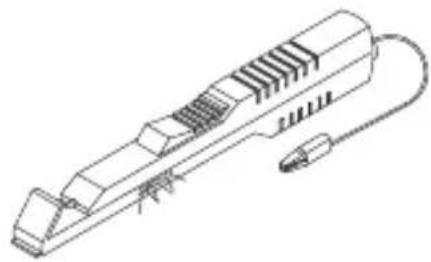
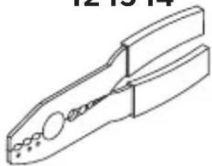
- Use a crimping tool (fig. 1 12, page 3) to connect the cables.
- Screw the cable when connecting cable 31 (earth)
– Screw on the cable using a cable lug and gear disc to one of the vehicle ' s earth bolts or
Screw the cable to the sheet metal body work using a cable lug and a self-tapping screw.
Make sure there is a good earth connection.
If you disconnect the negative terminal of the battery, all data stored in the comfort electronics volatile memory will be lost.
-
The following data must be reset, depending on the vehicle equipment options:
-
Räd i o c o d e
- Vehicular Lock
- T i m e r
-
On-board computer
-
S e a t p o s i t i o n
You can find instructions for making these settings in the operating manual.
Note the following instructions during installation:

CAUTION!
- Secure the monitor in such a way that it cannot become loose under any circumstances (sudden braking, accidents) and cause injuries to the occupants of the vehicle.
- Do not attach the monitor in the air bag deployment path, as this could cause injury if the airbags are triggered.
Observe the following instructions when working with electrical parts:
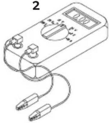
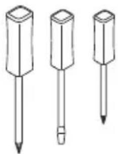
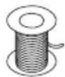
- When testing the voltage in electrical cables, only use a diode test lamp (fig. 1, page 3) or a voltmeter (fig. 2, page 3).
Test lamps with a bulb (fig. 1 3, page 3) consume voltages which are too high and can damage the vehicle's electronic system.
-
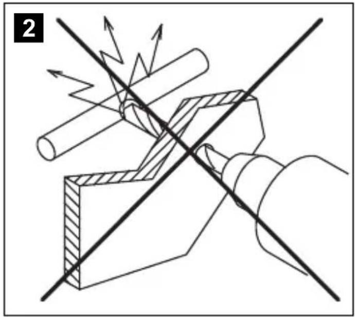
When making electrical connections, ensure that:
-
They are not kinked or twisted
- They do not rub on edges
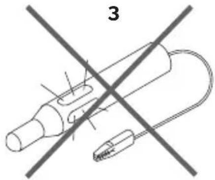
-
They are not laid in sharp-edged through-holes without protection (fig. 3, page 4)
-
Insulate all connections.
- Secure the cables against mechanical stress with cable binders or insulating tape, for example, to existing lines.
Observe the following instructions when handling the LCD monitor:

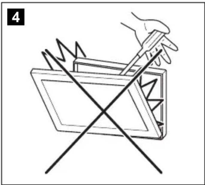
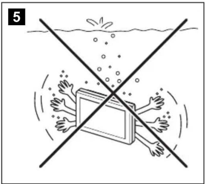
CAUTION!
- People (including children) whose physical, sensory or mental capacities or whose lack of experience or knowledge prevent them from using this product safely should not use it without the supervision or instruction of a responsible person.
- Do not open the monitor (fig. 4, page 4)
- Do not immerse the monitor in water (fig. 5, page 4); the monitor is not waterproof.
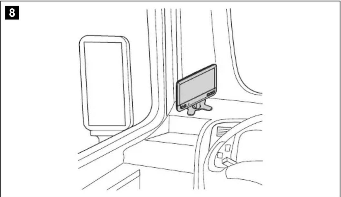
- The monitor must not impair your vision when driving (fig. 8, page 5).
- Do not operate the monitor with wet hands.
- Do not operate the monitor if the housing has been damaged.

NOTICE!
- Connect it to the correct voltage.
-
Do not use the monitor in areas which:
-
Are subject to direct sunlight
- Are subject to strong temperature fluctuations
- Have high levels of humidity
- Are poorly ventilated
-
Are dusty or oily
-
Do not press against the LCD display.
- Do not drop the monitor.
- If you use the monitor in vehicles, the vehicle should be running during operation to prevent the vehicle battery from discharging.
- The picture quality can be impaired in the vicinity of electromagnetic fields. For this reason do not mount the monitor near loudspeakers.
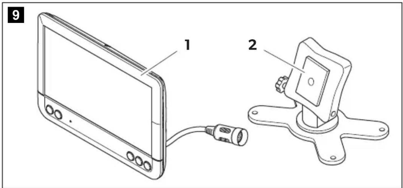
3 S C O P E O F D E I
No. in fig. 9, page 5
Quantity Description Ref. no.
1 Monitor 9600011060
21 Monitor bracket 9102200193
31 Monitor bracket cover -
- 1 Connection cable
9102200056
Fastening material
4 I n t e n d e d u s
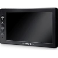
The PerfectView M71LLCD monitor (ref no. 9600011060) is primarily intended for use in vehicles. It can be used to connect cameras (e.g. a reversing video system) or other video sources.
The LCD monitor is designed for use in all vehicles.
The LCD monitor is suitable for commercial use.
This product is only suitable for the intended purpose and application in accordance with these instructions.
This manual provides information that is necessary for proper installation and/or operation of the product. Poor installation and/or improper operating or maintenance will result in unsatisfactory performance and a possible failure.
The manufacturer accepts no liability for any injury or damage to the product resulting from:
-
Incorrect assembly or connection, including excess voltage
-
Incorrect maintenance or use of spare parts other than original spare parts provided by the manufacturer
- Alterations to the product without express permission from the manufacturer
- Use for purposes other than those described in this manual
Dometic reserves the right to change product appearance and product specifications.
5 Technical description
5.1 Function description
The LCD monitor can be connected to cameras (e.g. reversing video systems) or other video sources (e.g. DVD players). It is possible to switch back and forth between video sources.
The monitor features control cables which allow the cameras to be activated automatically.
It can operate up to four cameras, which can be activated via external control cables or manually. This monitor also features a distance grid in the display which is activated automatically when the reverse gear is engaged (AV1).
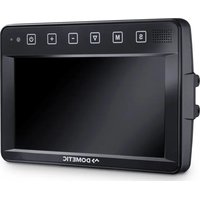
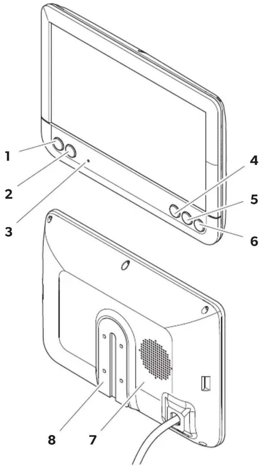
5.2 Control elements
The following control elements are located on the monitor:
No. in
fig. 10,
page 6
Description
1 Switches the monitor on and off.
2 Switches to setup mode.
3 The light sensor automatically adjusts the brightness of the display to the ambient light.
4 - Reduces the audio volume or the selected parameter (brightness, contrast, color).
5 + Increases the audio volume or the selected parameter (brightness, contrast, color).
6 Selects the camera.
7
M
O
n
8 Loudspeaker
6 Installing the LCD monitor
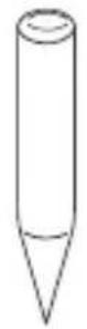
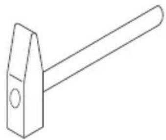
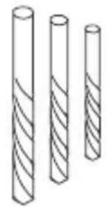
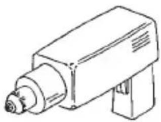
6.1 Tools required (fig. 1, page 3)
For installation and assembly you will need the following tools:
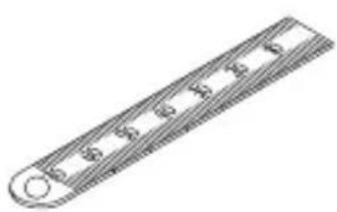
- Measuring ruler (4)
- Center punch (5)
- H a m m e r ( 6)
- Drill head set (7)
- Drill (8)
- Screwdriver (9)
To establish and test the electrical connection, the following tools are required:
- Diode test lamp (1) or voltmeter (2)
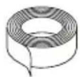
Insulating tape (10) - Heat shrinking sleeve
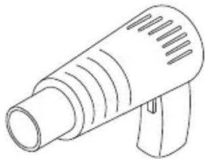
Hot air blower (11)
Crimping tool (12) - Soldering iron (optional) (13)
- Solder (optional) (14)
- Cable bushing sleeves (optional)
To fasten the cables, you may require additional cable binders.
6.2 Installing the monitor

CAUTION! Beware of injury!
Select the location of the monitor so that it cannot injure the passengers in the vehicle under any circumstances (e.g. sudden braking, road traffic accidents).
Note the following instructions during installation:
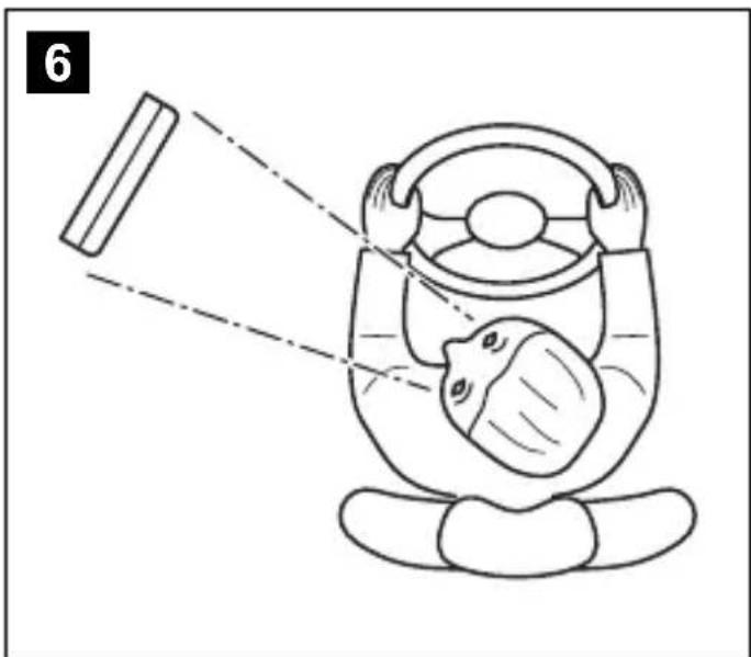
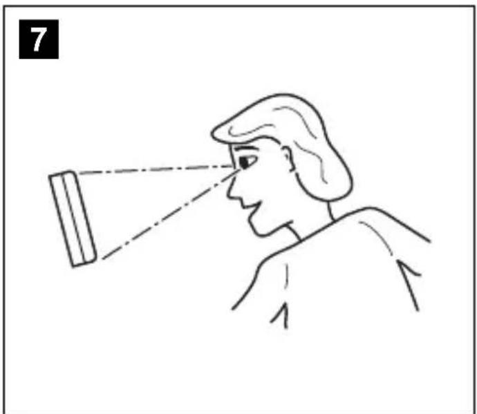
- Select an installation location that provides an unobstructed view of the monitor (fig. 6 and fig. 7, page 4).
- Never install the monitor in areas where your head could hit it or in the airbag deployment path. This could cause injury if the airbag opens.
- The monitor must not impair your vision when driving (fig. 8, page 5).
- The installation location should be flat.
-
Check that there is sufficient space underneath the installation location to attach the washers and nuts.
-
Check beforehand that there is sufficient space on the other side for the drill head to come out (fig. 2, page 4).
- Bear in mind the weight of the monitor. Provide reinforcement if necessary (larger washers or plates).
- Make sure you can lay the connection cable to the monitor.
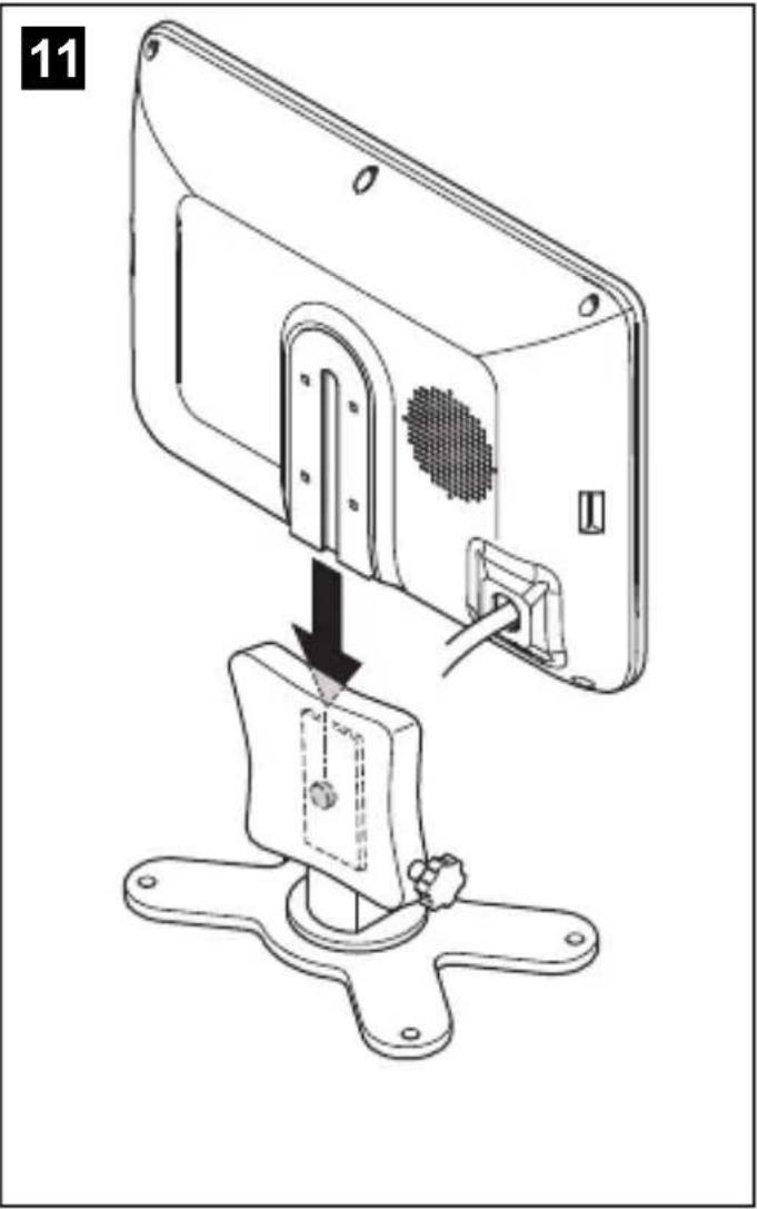
Choosing the installation location (fig. 11, page 7)
Place the monitor on the monitor bracket.
Position the monitor and the attached monitor bracket provisionally.
Mark the outlines of the corners of the support base on the dashboard.
Take the monitor off the monitor bracket.
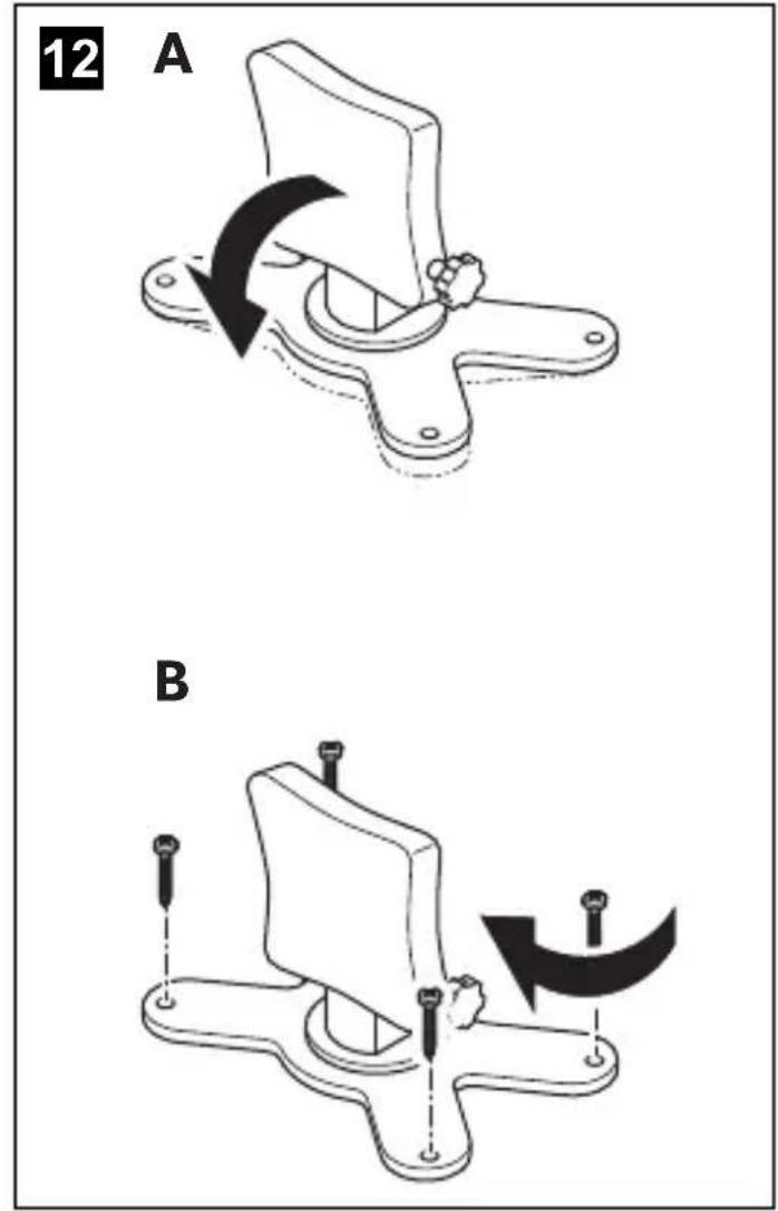
Screwing the monitor bracket onto the dashboard (fig. 12, page 7)
Hold the support base within the outlines marked beforehand.
Fix the monitor bracket in place using suitable screws.
Fastening the monitor
Set the monitor on the monitor bracket and secure it with the knurled nut (fig. 11, page 7).
6.3 Connecting the monitor electrically
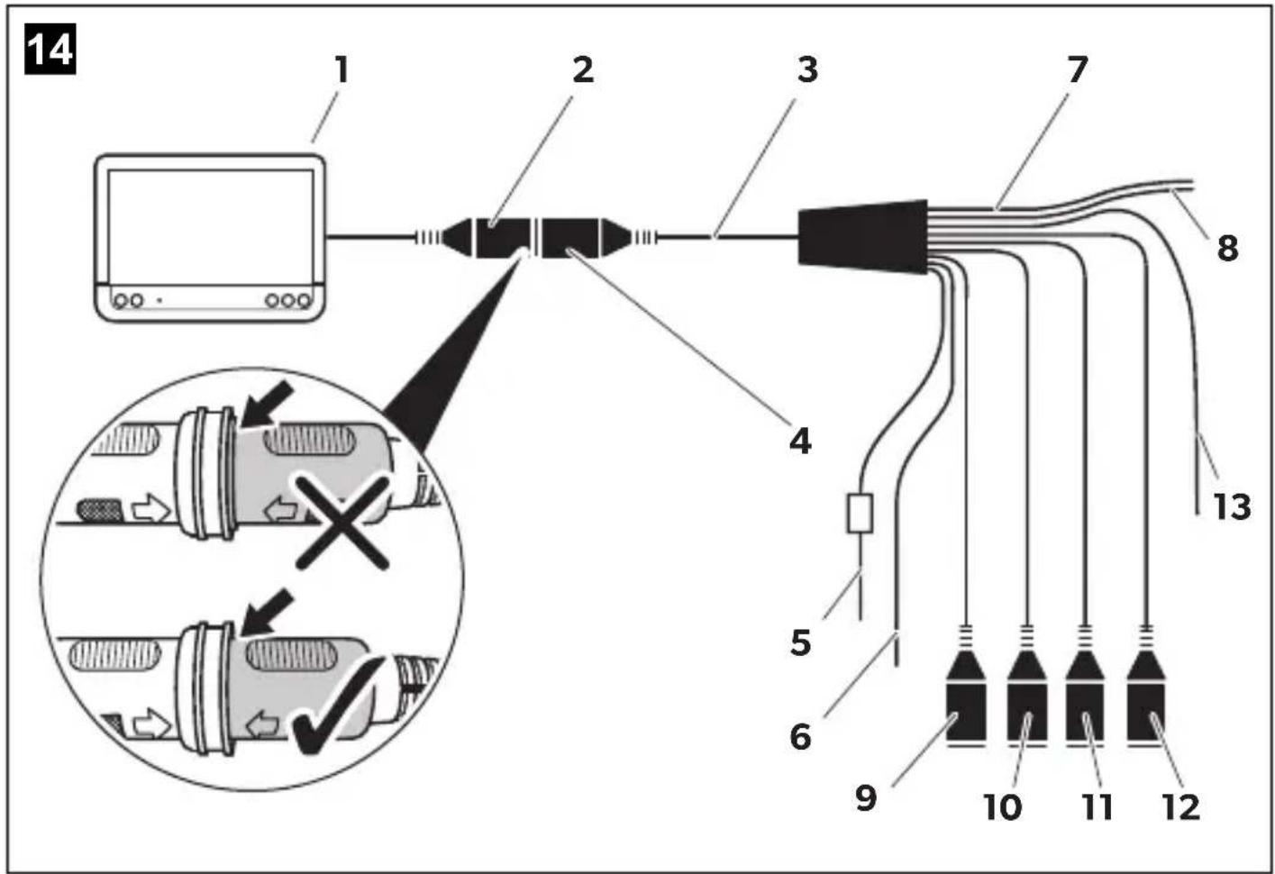
The circuit diagram for the LCD monitor can be found in fig. 14, page 8.
| No. Description | |||||||
| 1 | M | o | n | i | t | o | r |
| 2 | 2 | 0 | - | p | i | n | s |
| 3 Monitor line | |||||||
| 4 20-pin plug | |||||||
| 5 | 12 - 24 V positive cable (red): connected to the positive terminal of the ignition (connected positive, terminal 15) or the positive terminal of the battery (terminal 30) | ||||||
| 6 Earth cable (black): connected to the negative terminal of the voltage source | |||||||
| 7 Cable (green): control input for video input AV1, such as for connecting the reversing light | |||||||
| 8 Cable (white): control input for video input AV2, such as for the side camera | |||||||
| No. Description |
| 9 6-pin AV1 socket (connection to video source 1) |
| 10 6-pin AV2 socket (connection to video source 2) |
| 11 6-pin AV3 socket (connection to video source 3) |
| 12 6-pin AV4 socket (connection to video source 4, with video signal detection) (optional) |
| 13 Cable (blue): control input for video input AV3 (optional) |

NOTICE!
Cables and cable connections that are not properly installed will cause malfunctions or damage to components.
Correct installation of cables and cable connections ensures lasting and trouble-free operation of the retrofitted components.
Observe the following instructions when laying the connection cables:
- If possible, use existing through-holes for feeding through the connection cables, or other suitable options, such as ventilation grilles. If there are no existing through-holes, you must drill a hole of 22 mm . Check beforehand that there is sufficient space on the other side for the drill head to emerge (fig. 2 , page 4).
- Cover the holes with the feed through (fig. 12, page 7) in the base of the monitor bracket.
- To prevent damage to the cables, when laying them ensure that there is always a sufficient distance to vehicle components which can become hot (lights, heaters, ventilators etc.).
-
When laying the cables (fig. 3, page 4), make sure:
-
They are not kinked or twisted
- They do not rub on edges
- They are not laid in sharp-edged through-holes without protection
Connecting the monitor as a reversing video system (fig. 14, page 8)
Lay the connection cable for the monitor bracket on the dashboard.
Insert the plug of the monitor cable (2) into the socket (4) of the connection cable (3). Wait until you hear the plug snap in.

NOTICE! Risk of damage!
Make sure the polarity is correct when connecting to a voltage source.
Connect the red and black cables of the connection cable to a suitable voltage supply:
- Connect the red cable (5) to terminal 15 (ignition).
- Connect the black cable (6) to terminal 31 (earth).
If the monitor is to be activated when reverse gear is selected, connect the green cable (7) to the positive cable of the reversing light.

NOTE
If voltage is present at the green cable (7), the reversing camera is activated. The reversing camera has priority.
If the monitor is to be activated e.g. when the indicator is flashing, connect the following control cable to a positive cable of the indicator:
- white cable (8), blue cable (13)

NOTE
If voltage is present in this control cable, the video inputs AV2 and AV3 will be activated.
This control cable is used as a signal cable for the activation of a side camera when an indicator is flashing, for example.
If necessary, connect the AV1 socket (9) of the connection cable to the plug of video source 1 (e.g. reversing camera).
If necessary, connect the AV2 socket (10) of the connection cable to the plug of the video source 2 (e.g. side camera).
If necessary, connect the AV3 socket (11) of the connection cable to the plug of video source 3 (e.g. camera).

NOTE
Observe the power consumption of the video system. The cameras are equipped with heaters. A maximum current of 1.5 A can flow (three cameras in heating mode). Use a disconnecter switch for direct connection to the battery. This allows you to disconnect the video system from the battery easily if you are no longer using the vehicle.
Connecting an additional reversing camera (trailer operation)
If necessary, connect socket AV4 (12) of the connection cable to the plug of the additional reversing camera.
7 Using the LCD monitor
7.1 Switching on the monitor
If the monitor is switched off, press the button (fig. 10 2, page 6) to switch the monitor on.
The button lights up blue.
The picture appears.
7.2 Switching off the monitor
Press the button (fig. 10 2, page 6) to switch off the monitor.
The button lights up red.
The picture disappears.
7.3 Setting the monitor
To set the monitor to suit your requirements, proceed as follows (fig. 10, page 6):
Press the " " button (5) to call up the required parameter.
The parameters to be set are displayed in the following sequence:
-Brightness:0-100
- Contrast: 0 - 100
- Saturation: 0 - 100
Volume: 0-100
- Language: English, French, German
- Mirror AV1/AV2/AV3/AV4: Yes or No
- Video AV1/AV2/AV3/AV4: Yes or No
- Distance grid: ON or OFF
- Trailer detection: ON or OFF
- Day/night mode: ON or OFF
- Default: Default setting for all parameters
Press the "+" button (3) or the "-" button (4) to set the required parameter.
Press the "+" button (3) to increase the value of the selected parameter.
Press the - button (4) to reduce the value of the selected parameter.
7.4 Setting the video source
Proceed as follows to set the video source (fig. 10, page 6):
If you would like to switch to a different video source, press the button (6).
The monitor changes the camera in the order Camera 1 - Camera 2 - Camera 3 - Camera 4.
With the Video AV1/AV2/AV3/AV4 parameter, video inputs that are not used can be switched to inactive. These empty inputs are then skipped over.
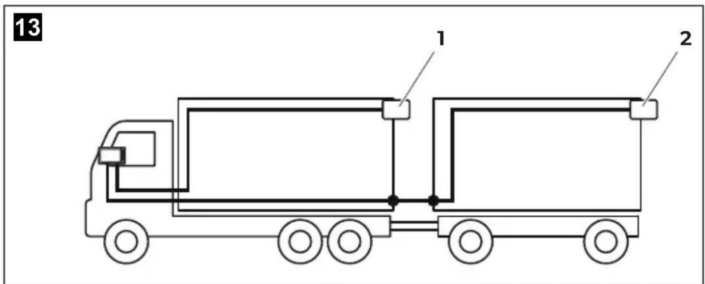
7.5 Detecting the trailer camera
This function is required when using a trailer camera (fig. 13, page 7) if the system is activated automatically via the reverse gear.
- One camera connected (e.g. towing vehicle without a trailer):
the camera connected to AV1 (1) is activated.
- Two cameras connected (e.g. towing vehicle with a trailer):
the camera connected to AV4 (2) is activated (AV1 is inactive).
8 Cleaning and maintaining the LCD monitor

NOTICE! Risk of damage!
- Do not use sharp or hard objects for cleaning, as these may damage the monitor.
- Remove the cable before cleaning the monitor to prevent short circuiting.
Clean the monitor with a soft, damp cloth from time to time.
9 W a r r a n t y
The statutory warranty period applies. If the product is defective, please contact the manufacturer's branch in your country (see dometic.com/dealer) or your retailer.
For repair and warranty processing, please send the following items:
- Defect components
A copy of the receipt with purchasing date - A reason for the claim or description of the fault
10 Disposal
Place the packaging material in the appropriate recycling waste bins, wherever possible.

If you wish to finally dispose of the product, ask your local recycling center or specialist dealer for details about how to do this in accordance with the applicable disposal regulations.
11 Technical data
| M71L | |
| Ref. no.: 9600011060 | |
| Type: Color TFT LCD | |
| Display size: 7" (17.8 cm) | |
| Brightness: Approx. 500 cd/m2 | |
| Display resolution, H x V: 800 x 480 pixels | |
| Viewing angle: | vertical: above 50°, below 70°, horizontal: right/left: 70° |
| Television standard: | PAL/NTSC (automatic switching) |
| Operating voltage: | 12 - 32 V= |
| Output: | maximum 10 W |
| Operating temperature: | -20 °C to +70 °C |
| Storage temperature: | -30 °C to +80 °C |
| Vibration resistance: | 6 g |
| Dimensions W x H x D: | 174 x 125 x 26 mm |
| Weight: | 400 g |
Certifications
This device has E8 approval.


No. in fig. 9, page 5
AVIS!
5 Description technique
He INCNoB3yIte KneMMHbIe KONoDKN.
-
Д�� coeingня ka6epeи nCnoB3yIte o6xHmHbIe Kneu (pnc. 1 12, ctrp. 3).
-Приивinte ka6eь, ecnnpo3BODITc coeHHeNe K npOBoy 31 (kopnyc): -
c nOMOJIIO Ka6eIbHOrO HaKOHeuHnKa I 3y6UaToI npxHHoJ ⅢaIbI K BnHTy dIra CoEINHeHNr C KopnyCOM, IMeIoUeMycr Ha aBTOMO6nne HII
- C NOMOUIKAb6eBbHOro HaKOHeuHnKa I CaMOHaPe3aIOUeRo BNHTa K NINCTy Ky3OBA.
O6ecnebTe HaedxHoe coeHNHeHn c Kopnycom!
Pn OTcoeHHeHH KTeMMbI OTPuateBHO TONIOca aKKyMylTopHO 6aTapeN BCE 3HepeO3aBNCMbIe 3JIeKTPoHHbIe 3aIOMHaUoUne yCTPOINCTBa CNCTEm KOMOpOpTa TepJOT COXpaHeHHbIe B HIX DaHHbIe.
- Bo3MOxHNO, notpe6yETcra 3aHOBO NaCTpOntb cneDyUoIe daHHbIe:
-KoIpaIIOnpneMHNka
- Yacbl aBTOMO6nJIa
- T\aɪm e p
- BopTOBOI KOMNbIOTep
-NonoxeHne cndeHn
Yka3aHnI NO HacTpoIKe npINBeHeB I B COOTBeTCTByIOUe INHCTpyKuINI NO 3KcNpyTaUIN.
PnMOHTaKe BbINOHNrB CneyIOuHne yKa3aHn:

OCTOPOXHO!
- KpeNTe MOHTOp TaK, YTO6bl OH Hn npN KaKnx ycNoBnx (pe3KOM TOpMOxHn, aBa-pn) He MoT OTCoEINHtbcra N TpaBMnPoBaTb NaCCaxNpOB.
He KpeHnTe MOHITOp B paDnUcSe DeICTBnRA NaDbYBbIX NODyUeK 6e3OnaCHOCTN, T. K. B npOTNBHom Cnyuae Pn INx Cpa6aTbBAHn IMeETcR ONaCHOCTb TpaBMnPOBaHn.
Pn pa6oax Ha 3neKtpuecko cnCTe mo6IouaIte cIeDyUOu ne yka3aHn:
MOnHTOp nMeet ynpabnIoune Ka6eN, C NOMOuKOTOpbIX MOxHO aBTOMaTnueCKn aKTINBnPOBaTb KaMepbl.
IopdepxnBaetcpa6ota do yeBipex kamep; kamepbMOxHO aKTNBIPoBaTb BpyHyIO npn HAnuHn BHeuHee ynpaBnIooero Ka6eJI. MoHTOp DOONHITeJbHO IMeET Ha DInCIIee INDnKaTOp paCToR HN, KOTOpBn ABTomAtnueeKn aKTNBIPyeTc npn BKNIOUeHN Npeepaun 3aDHeO XoJa (AV1).
5.2 ΘleMeHTbI ynpabLeHn
HaMOHTopeIMeIOTcSlJeDyUOJIe 3JeMeHTbI ynpaBHeHn:
No Ha pnc.10, Onncahne ctp.6
1 BkIIOUaET N BbIKIOUaET MOHITOp.
2 Bknoaetpexim HacrpoKn.
3ДaTnK OCBeUeHnR, KOTOpbI aBToMaTuYeCKn peRyNpPyET rPkOCTb 3KpaHa B 3aBnCmOCTn OT YcNoBn OCBeUeHnR.
4 - YMeHbShaet rPOMKOCTb nIIN dpyroN npaMeTp (rpkocTB, KOHTpactHOCTb, ZBET).
PnBnHcNbAHne KpOHSeHa MOHTopa K nAHeI np6OpOB (pnc. 12, ctp. 7)
YctaHOBtTe OCHOBaHHe KpOHSteHa B npeDeNaX paHee pa3MeueHHbIX rpaHnL.
3aKpeNITe KPOHHTeINH MOHITOPa NOxOJaUMN BnHTaMn.
KpenneHne MoHntopa
YctaHOBInTe MoHITOp Ha KPOHHTeIN H 3aΦnKcnpyIte erO raIKoN cHaKaTkoN (pnc. 11, ctp. 7).
MoHHTOP MOXHO HAcTPONTb B COOTBcETCTBn CO CBOUMN IpeIIOuTeHNrMaMn (pnc. 10, ctp. 6):
Дя Вьбopa Требуемо napametpa НхмITE KhoIGNky «» (5).
HactpaBaeMbIe npaMeTpbl OTo6paXaHTc B CneDyUoJe NocpeNoBaTeNbHOCTn:
-Ярковь («Brightness»): 0 - 100
-KoHTpaCTHOCTb («Contrast»): 0-100
-HacbIeHHocTb («Saturation»): 0-100
-「pomKocTb(«Volume»):0-100
-Язвк(«Language»):ангийски,фраунузkn,HeMeцкн
- 3ePkabHoe oTo6paJenne AV1/AV2/AV3/AV4 («Mirror AV1/AV2/AV3/AV4»): «Дa» ип «HeT»
-Виdeo AV1/AV2/AV3/AV4(«Video AV1/AV2/AV3/AV4»): «Да» по «Нет»
-Указа teль расстони(«Distance Grid»):«ВКЛ»unn «ВыКЛ»
- Pacno3HaBHe npuεena («Trailer Detection»): «BKЛ» уи «ВblKЛ»
-HouHoi nDHeBHOJ pexmbl(«Day/Night»): «BKJI» iIN «BbIKI»
- C6poc («Default»): 3aBODCKne HacTpoKn BCex npaMeTPOB
Дян ac troponи trpe6yemoro napametpa haxmnte KhoNky «+» (3) nIn KhoNky «-» (4).
Haxmnte KhoNky + - (3), yTo6bI yBennuTb 3NaueHne BbI6paHHoro npaMeTpa.
Haxmnte KhoNky «-» (4), yTo6bI yMeHbUHTb 3NaueHne Bbl6paHHoro napaMeTpa.
7.4 HactpoIka nctouHnKa BndeocnHaJa
Дянстpoи Источиka BndeocnHaа BbInonHnTe cneDyUoee (pnc. 10, ctrp. 6):
InpeeknoeHna nctouHnka BndeocnHaHa na Haxmnte KhoNky (6).
√ MoHntOp cMeHЯET n3O6paXeHnry OT KaMep B CNeIyUoIeN NOcIeIOBaTeIbHOCTN: «KaMepa 1 - KaMepa 2 - KaMepa 3 - KaMepa 4».
C nOmoIbIIO npaMeTpA «Video AV1/AV2/AV3/AV4» moXHO OTKJIIOUHTb HEnHyXHbIe BnIDeOBXoDbI.
Hencnonb3yeMbIe BnDeoBXOdbI He oTo6paXaOTc.
7.5 Pacno3HaBHe KamepbI npuena
3TaФункия pa6otaet pri NaHnUHH KAmepbI npuEena (pnc. 13, ctp. 7), KoTda CnCTema aBTOMaTHUeCKN aKTNBnpyeTcC NOMOuBIO 3aDHei Nepeaun.
dometic.com/sales-offices