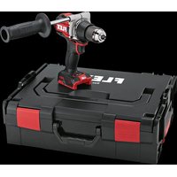
DD 2G 18.0-EC HD - Drill Flex - Free user manual and instructions
Find the device manual for free DD 2G 18.0-EC HD Flex in PDF.


User questions about DD 2G 18.0-EC HD Flex
0 question about this device. Answer the ones you know or ask your own.
Ask a new question about this device
Download the instructions for your Drill in PDF format for free! Find your manual DD 2G 18.0-EC HD - Flex and take your electronic device back in hand. On this page are published all the documents necessary for the use of your device. DD 2G 18.0-EC HD by Flex.
USER MANUAL DD 2G 18.0-EC HD Flex
text_image
B EC "clic"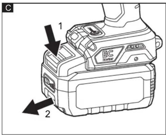
text_image
C 1 EC 2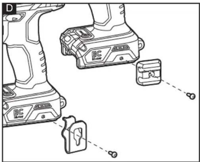
text_image
D EC Motor ABC EC Motor 8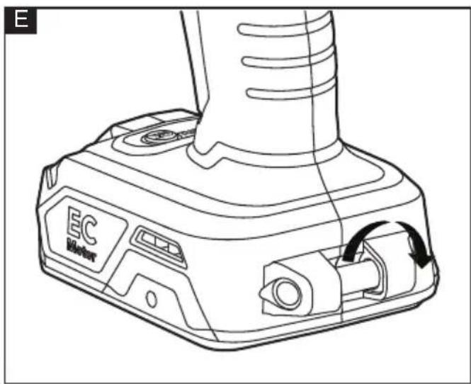
natural_image
Line drawing of a EC motor with labeled ports and rotation arrow (no text or symbols beyond branding)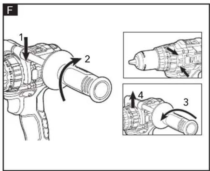
text_image
F 1 2 3 4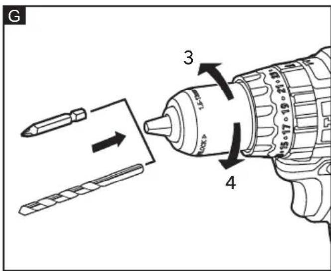
text_image
G 3 1.5mm 20kV 4 15:17:19:21:18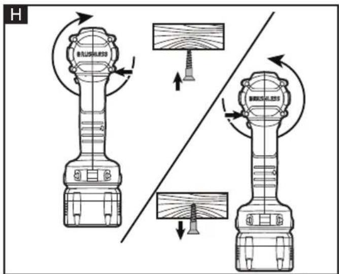
text_image
H BASILELESS BASILELESS BASILELESS BASILELESS BASILELESS BASILELESS BASILELESS BASILELESS BASILELESS BASILELESS BASILELESS BASILELESS BASILELESS BASILELESS BASILELESS BASILELESS BASILELESS BASILELESS BASILELESS BASILELESS BASILELess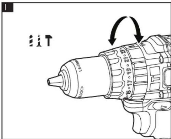
text_image
Technical diagram of a drill bit with directional arrows and component labels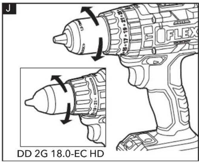
text_image
J DD 2G 18.0-EC HD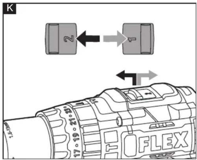
text_image
K 2 1 17·19·21·22 FLEX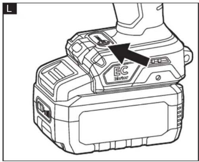
text_image
L EC Monitor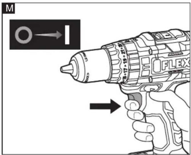
text_image
M 18.17-19-20-21 FLEX®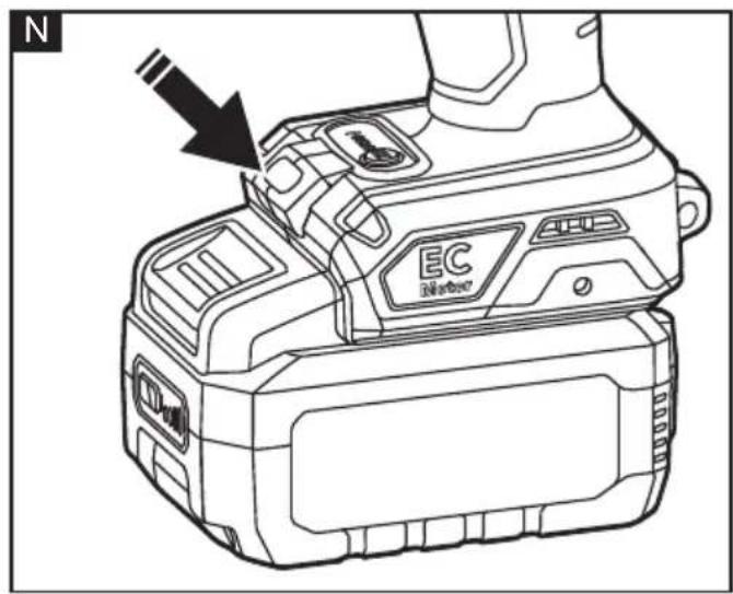
text_image
N EC MeritorSymbols used in this manual

WARNING!
Denotes impending danger. Non-observance of this warning may result in death or extremely severe injuries.

CAUTION!
Denotes a possibly dangerous situation. Non-observance of this warning may result in slight injury or damage to property.

NOTE
Denotes application tips and important information.
Symbols on the power tool
V
Volts
/min Rotation rate

To reduce the risk of injury, read the operating instructions!

Disposal information for the old machine (see page 17)!
For your safety

WARNING!
Before using the power tool, please read the follow:
– these operating instructions,
- the "General safety instructions" on the handling of power tools in the enclosed booklet (leaflet-no.: 315.915),
– the currently valid site rules and the regulations for the prevention of accidents.
This power tool is state of the art and has been constructed in accordance with the acknowledged safety regulations.
Nevertheless, when in use, the power tool may be a danger to life and limb of the user or a third party, or the power tool or other property may be damaged.
The percussion drill driver may be used only –asintended,
- in perfect working order.
Faults which impair safety must be repaired immediately.
Intended use
The cordless drill driver/hammer drill is intended.
– for commercial use in industry and trade,
– for inserting and releasing screws
– for drilling in wood, metal, ceramic and plastic,
- for impact drilling in brick, masonry and stone (only for PD 2G 18.0-EC HD).
Safety instructions for percussion drill driver

WARNING!
Read all safety warnings, instructions, illustrations and specifications provided with this power tool. Failure to follow all instructions listed below may result in electric shock, fire and/or serious injury. Save all warnings and instructions for future reference.
- Hold the power tool by insulated gripping surfaces, when performing an operation where the cutting accessory or fastener may contact hidden wiring. The cutting accessory or fastener contacting a "live" wire may make exposed metal parts of the power tool "live" and could give the operator an electric shock.
Safety instructions when using long drill bits:
■ Never operate at higher speed than the maximum speed rating of the drill bit.
At higher speeds, the bit is likely to bend if allowed to rotate freely without contacting the workpiece, resulting in personal injury.
■ Always start drilling at low speed and with the bit tip in contact with the workpiece. At higher speeds, the bit is likely to bend if allowed to rotate freely without contacting the workpiece, resulting in personal injury.
■ Apply pressure only in direct line with the bit and do not apply excessive pressure. Bits can bend causing breakage or loss of control, resulting in personal injury.
■ Use auxiliary handles if these are supplied with the power tool. The loss of control may result in injuries.
■ Use suitable detectors to detect concealed power supply cables or consult your local supply company.
Contact with electric cables may result in a fire and/or electric shock. A damaged gas pipe may cause an explosion. Cutting into a water pipe will cause damage to property.
■ Switch off the power tool immediately when the cutting accessory jams. Be prepared for high reaction torques which cause kickback. The cutting accessory jams when:
- the power tool is overloaded or
- it snags in the workpiece to be machined.
■ Maintain a firm grip on the power tool. High reaction torques can occur briefly when screws are tightened and released. - Secure the workpiece. A workpiece is held more securely in a clamping device or vice than by hand.
■ Wait until the power tool has come to a stop before putting it down. The cutting accessory may snag, causing the operator to lose control of the power tool.
■ Use only original batteries with the voltage indicated on the type plate of your power tool. The use of other batteries, e.g. imitations, reconditioned batteries or other makes, increases the risk of injury and damage to property by exploding batteries.
■ Wear ear defenders when impact drilling. The effect of noise may result in loss of hearing.
Noise and vibration
The noise and vibration values have been determined in accordance with EN 62841.
The A evaluated noise level of the power tool is typically:
- Sound pressure level L_pA : PD 2G 18.0-EC HD 89.1 dB(A) DD 2G 18.0-EC HD 82 dB(A)
- Sound power level L_WA : PD 2G 18.0-EC HD 100.1 dB(A) DD 2G 18.0-EC HD 90 dB(A)
- Uncertainty: K = 5 dB. Total vibration value :
- Emissionswert a_h,D :
PD 2G 18.0-EC HD 2.5 m/s ^2 DD 2G 18.0-EC HD <2.5 m/s ^2
- Emission value a_h, ID :
PD 2G 18.0-EC HD 16.5 m/s ^4 - Uncertainty: K = 1.5 m/s^2
CAUTION!
The indicated measurements refer to new power tools. Daily use causes the noise and vibration values to change.
NOTE
The vibration emission level given in this information sheet has been measured in accordance with a measurement method standardised in EN 62841 and may be used to compare one tool with another.
It may be used for a preliminary assessment of exposure. The specified vibration emission level represents the main applications of the tool.
However, if the tool is used for different applications, with different cutting accessories or poorly maintained, the vibration emission level may differ.
This may significantly increase the exposure level over the total working period.
To make an accurate estimation of the vibration exposure level, it is also necessary to take into account the times when the tool is switched off or running but not actually in use.
This may significantly decrease the exposure level over the total working period.
Identify additional safety measures to protect the operator from the effects of vibration such as: maintain the tool and the cutting accessories, keep the hands warm, organisation of work patterns.
CAUTION!
Wear ear defenders at a sound pressure above 85 dB(A).
Technical data
| Tool | PD 2G 18.0-EC HD | DD 2G 18.0-EC HD |
| Type | Percussion drill driver | Drill driver |
| Torque settings 23 | 21 |
| Max. torque | Nm 70 | /158 70 / 158 | |
| No-load speed | r.p.m | 0-550/2000 0 | -550/2000 |
| TURBO speed | r.p.m | 0-700/2500 0 | -700/2500 |
| Impact rate | bpm | 0-8800/32000 | - |
| TURBO impact rate | bpm | 0-11200/40000 | - |
| Chuck mm | 13 13 | ||
| Max. drill diameter - in wood - in steel - in masonry | mm mm mm | 89 13 16 | 89 13 - |
| Weight according to"EPTA Procedure 01/2003" (without battery) | kg 1.6 | 8 1.6 |
| Battery AP 2.5 | AP 5.0 AP | 8.0 | |
| Weight of battery/kg | 0,42 0,72 | 1,18 | |
| Working Temperature | -10~40°C | ||
| Charging Temperature | 4~40°C | ||
| Storage Temperature | 0~50°C | ||
| Charger | CA 10.8/18.0, CA 18.0-LD | ||
Overview (see figure A)
The numbering of the product features refers to the illustration of the machine on the graphics page.
1 Trigger switch
For switching on and off and for accelerating up to maximum rotational speed
2 Direction preselector switch
3 Speed selector switch
4 Operating mode turning dial
5 Torque setting turning dial
6 Chuck jaws
7 Workplace lamp
8 Handle
9 Turbo function indicator light
10 Insertion slot for battery
11 Turbo function button
12 Auxiliary handle
13 Li-ion battery
14 Release button for battery
15 Power-indicator button
16 Power indicator
17 Belt clip
18 Fastening screw
19 Bit bracket
Operating instructions

WARNING!
Remove the battery before carrying out any work on the power tool.
Before switching on the power tool
Unpack the percussion drill driver and check that here are no missing or damaged parts.

NOTE
The batteries are not fully charged on delivery. Prior to initial operation, charge the batteries fully. Refer to the charger operating manual.
Inserting/replacing the battery
■ Press the charged battery13 into the power tool until it clicks into place (see figure B).
■ To remove, press the release button 14 and pull out the battery (see figure C).

CAUTION!
When the device is not in use, protect the battery contacts. Loose metal parts may short circuit the contacts; explosion and fire hazard!
Battery state of charge
■ Press the power indicator 15 button to check the state of power indicator 16.
■ When the lowest level of the power indicator starts flashing after pressing power indicator button, the battery must be recharged.
Removable belt clip and bit clip
■ Remove the battery pack from the tool.
■ Align the hole of the belt clip 17 and bit bracket 19 with the threaded hole on the base of the tool (see figure D).
■ Insert the fastening screw 18 and securely tighten the screw with a screwdriver (not included).
Strap fixing
- Strap fixing is provided to attach a wrist strap (not included) in order to reduce the chances of dropping your tool. Wrap the strip around your hand when carrying the tool (see figure E).
Fitting/removing the auxiliary handle

CAUTION!
Use auxiliary handle if these are supplied with the power tool. The loss of control may result in injuries (see figure F).
■ Remove the battery pack from the tool.
■ Place the direction preselector switch 2 in the center lock position.
■ Loosen the auxiliary handle 12 by turning the handle counterclockwise.
■ Align the raised portion on the auxiliary handle with the grooves on gearbox of the drill/driver, and then put the auxiliary handle onto the tool.
■ Hand-tighten the handle by turning the handle clockwise.
■ To remove the handle, loosen the auxiliary handle counterclockwise and remove it.
Install and remove bits (see figure G)

CAUTION!
Before carrying out any work on the power tool, move the direction preselector switch 2 to the middle position.
■ Lock the trigger switch 1 OFF on the tool by placing the direction preselector switch in the center position.
■ Grip the power tool firmly with one hand and turn the chuck with the other hand.
- Turn counterclockwise to open the chuck further.
- Turn clockwise to close the chuck.
- Insert the tool.
■ Close the chuck fully.

NOTE
Carry out a test run to check that the tool is chucked in the centre.

WARNING!
The bit may be hot after prolonged use. Use protective gloves when removing the bit from the tool, or first allow the bit to cool down.
Direction preselection (see figure H)

CAUTION!
Change the direction of rotation only when the power tool is stopped.
Move the direction preselector switch 2 to the required position:
■ Right: counterclockwise (remove screws, release screws)
■ Left: clockwise (drill, insert screws, tighten down screws)
■ Middle: switch-on interlock (tool change, when working on the power tool)
Operating mode (see figure I)

CAUTION!
Change the operating mode only when the power tool is stopped.
■ Move the operating mode turning dial 4 to the required position.
: Drilling
1: Screwing
T: Impact drilling
Only for PD 2G 18.0-EC HD
Torque preselection (see figure J)

CAUTION!
Change the torque only when the power tool is stopped.
Move the torque setting turning dial 5 to the required position.
Speed preselection (see figure K)

CAUTION!
Change the speed only when the power tool is stopped.
Move the speed selector switch3 to the required stage:
■ Low speed, high torque
■ High speed, low torque
Anti-kickback
- The anti-kickback feature enables better control of the drill and improves user's comfort. The drill automatically turns off in
case of a sudden and unexpected rotation of the drill.
■ To restart the drill, release the trigger switch and then turn the drill back on.
NOTE: The tool is equipped with a reverse protection function. When the drill rotates quickly, it will automatically stop. This is not a malfunction. This is a protection measure.
Turbo mode (see figure L)
In turbo mode the tool delivers higher rotation speed and higher RPM. The torque remains the same.
i NOTE
When operating in turbo mode, the tool depletes the battery pack faster.
i NOTE
The turbo mode cannot be activated or deactivated while the tool is in operation.
■ Press the turbo function button 11 to activate the turbo mode of the tool. The turbo function indicator light 9 will light up at the same time. When you press the trigger switch the tool will operate in turbo mode.
■ To turn off the turbo mode, release the trigger switch, and then press the turbo button. The indicator light will turn off and the tool will return to its "normal" mode.
Switching on the power tool (see figure M)
■ To switch the power tool on: Press the trigger switch 1.
The trigger switch allows the operator to increase the speed in increments up to the maximum speed.
■ To switch the power tool off: Release the trigger switch.
NOTE
When using the power tool continuously, the operator should work primarily with the trigger switch fully depressed.
Workplace lamp (see figure N)
■ Press trigger switch 1
– Workplace lamp lights up
■ Release trigger switch
– Workplace lamp goes out automatically after approx. 10 sec.
The workplace lamp will rapidly flash when the tool and/or battery pack becomes overloaded or too hot, and the internal sensors will turn the tool off. Rest the tool for a while or place the tool and battery pack separately under air flow to cool them.
The Workplace lamp will flash more slowly to indicate that the battery is at low-battery capacity. Recharge the battery pack.
Working with the power tool
CAUTION!
Before carrying out any work on the power tool, move the direction preselector switch to the middle position.
■ Insert the battery.
■ Set operating mode according to the work item.
■ Set torque preselection to the required setting.
■ Set speed to the required setting.
■ Set the required direction of rotation.
■ Hold the power tool with one hand on the handle and assume the working position. If the power tool is running, never actuate the direction preselector switch or torque setting turning dial.
■ Switch on the power tool.
■ At the end of work, release the trigger switch.
■ Move the direction preselector switch to the middle position.
Maintenance and care
WARNING!
Remove the battery before carrying out any work on the power tool.
Cleaning
■ Clean the power tool and grille in front of the vent slots regularly. Frequency of cleaning is dependent on the material and duration of use.
■ Regularly blow out the housing interior and motor with dry compressed air.
Spare parts and accessories
For other accessories, in particular tools and polishing aids, see the manufacturer's catalogues.
Exploded drawings and spare-part lists can
be found on our homepage:
www.flex-tools.com
Disposal information

WARNING!
Render redundant power tools unusable:
- mains operated power tool by removing the power cord,
- battery operated power tool by removing the battery.

EU countries only
Do not throw electric power tools into the household waste!
In accordance with the European Directive 2012/19/EU on Waste Electrical and Electronic Equipment and transposition into national law used electric power tools must be collected separately and recycled in an environmentally friendly manner.

Raw material recovery instead of waste disposal.
Device, accessories and packaging should be recycled in an environmentally friendly manner. Plastic parts are identified for recycling according to material type.

WARNING!
Do not throw batteries into the household waste, fire or water. Do not open used batteries.
EU countries only:
In accordance with Directive 2006/66/EC defective or used batteries must be recycled.

NOTE
Please ask your dealer about disposal options!
C €-Declaration of conformity
We declare on our sole responsibility that the product described in "Technical specifications" conforms to the following standards or normative documents:
EN 62841 in accordance with the regulations of the directives 2014/30/EU,
2006/42/EC, 2011/65/EU.
Responsible for technical documents:
Peter Lameli Klaus Peter Weinper Technical Head Head of Quality
Department (QD)
Declaration of Conformity
We as the manufacturer: FLEX
Business address: Bahnhofstr. 15, 71711 Steinheim, Germany
declare under our sole responsibility, that the product(s) described under „Technical specifications“ fulfills all the relevant provisions of The Supply of Machinery
(Safety) Regulations S.I. 2008/1597 and also fulfills all the relevant provisions of the following UK Regulations:
Electromagnetic Compatibility Regulations S.I. 2016/1091, The Restriction of the Use of Certain Hazardous Substances in Electrical and Electronic Equipment Regulations
S.I. 2012/3032 and are manufactured in accordance with the following designated Standards:
BS EN 62841-1:2015,
BS EN 62841-2-1:2014,
BS EN 55014-1:2017,
BS EN 55014-2:2015
Place of declaration: Steinheim, Germany.
Responsible person: Peter Lameli, Technical Director - FLEX-Elektrowerkzeuge GmbH
Contact details for Great Britain: FLEX Power
Tools Limited, Unit 8 Anglo Office Park,
Lincoln Road, HP 12, 3RH Buckinghamshire, United Kingdom.

text_image
i.v. P###nd Peter Lameli Technical Head Klaus Peter Weinper Head of Quality Department (QD)19.05.2021
Exemption from liability
The manufacturer and his representative are not liable for any damage and lost profit due to interruption in business caused by the product or by an unusable product.
The manufacturer and his representative are not liable for any damage which was caused by improper use of the product or by use of the product with products from other manufacturers.
To reduce the risk of injury, read the operating instructions!

Peter Lameli Klaus Peter Weinper Technical Head Head of Quality Department
Technical Head Head of Quality
Department (QD)
Peter Lameli Klaus Peter Weinper Technical Head Head of Quality
Department (QD)
1: Kruvide keeramine
T: Löökpuurimine
ainult PD 2G 18.0-EC HD jaoks
Momendi eelvalik (vt. joon. J)

ETTEVAATUST!
Peter Lameli Klaus Peter Weinper Technical Head Head of Quality
Department (QD)
Peter Lameli Klaus Peter Weinper Technical Head Head of Quality
Department (QD)
Peter Lameli Klaus Peter Weinper Technical Head Head of Quality
Department (QD)
- بال Connectivity/Lifestyle/Transportation/Logistics/Logistics/Logistics/Logistics/Logistics/Logistics/Logistics/Logistics/Logistics/Logistics/Logistics/Logistics/Logistics/Logistics/Logistics/Logistics/Logistics/Logistics/Logistics/Logistics/Logistics/Logistics/Logistics/Logistics/Logistics/Logistics/Logistics/Logistics/Logistics/Logistics/Logistics/Logistics/Logistics/Logistics
Technical Head Head of Quality
Department (QD)