44319 - Measuring equipment Wiha - Free user manual and instructions
Find the device manual for free 44319 Wiha in PDF.

| Product type | Voltage and continuity tester |
| Brand | Wiha |
| Model | 44319 |
| Voltage range | 12 - 1000 V AC / 12 - 1500 V DC |
| Overvoltage category | CAT IV 1000 V |
| Protection degree | IP64 (enclosure protected against water splashes and dust) |
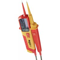
| Display | 13 LEDs + 4-digit backlit LCD screen |
| Dimensions (L x W x H) | 240 x 75 x 30 mm |
| Weight | Approx. 270 g |
| Power supply | 2 x 1.5 V AAA batteries (included) |
| Main functions | Voltage detection, single-pole phase test, rotating field test, continuity/diode test, data hold function |
| Self-test | Yes (check of LEDs, display, acoustic signal and lighting) |
| Acoustic signal | For dangerous voltage (> 50 V AC / > 120 V DC) and continuity |
| Measurement point lighting | Yes, integrated |
| Maintenance and cleaning | Clean with a slightly damp cloth; do not use abrasive products or solvents |
| Safety | Double or reinforced continuous insulation, TÜV Rheinland certification |
| Operating temperature | -5 to +40 °C |
| Storage temperature | -20 to +70 °C |
| Max. relative humidity | 85% |
| Max. operating altitude | 2000 m |
| Standards | EN 61010-1, EN 61243-3:2014 |
| Spare parts and repairability | Probes, batteries, adapters available through Wiha after-sales service; repair only by authorized service |
Frequently Asked Questions - 44319 Wiha
User questions about 44319 Wiha
0 question about this device. Answer the ones you know or ask your own.
Ask a new question about this device
Download the instructions for your Measuring equipment in PDF format for free! Find your manual 44319 - Wiha and take your electronic device back in hand. On this page are published all the documents necessary for the use of your device. 44319 by Wiha.
USER MANUAL 44319 Wiha
wiha Tools that work for you

| DE | 1 |
| EN | 8 |
| FR | 15 |
| NL | 22 |
| ES | 29 |
| IT | 36 |
| DA | 43 |
| NO | 50 |
| SV | 57 |
| FI | 64 |
| PL | 71 |
| CZ | 78 |
| RU | 85 |
| HU | 92 |
Inhaltsverzeichnis
About these instructions 8
Symbols in these instructions....8
Overview 8
Delivery contents 8
Scope of functions 9
Device parts 9
Symbols on your device 9
For your safety 10
Proper use 10
User requirements 10
Residual risks 10
Before use 10
Safety before use 10
Auto power on/off 11
Self test....11
Operation 12
Voltage test 12
Single-pole phase test 12
Rotation field test....12
Flow/diodes test 12
Data hold function 13
Replacing batteries 13
After use 13
Care 13
Transport and storage....13
Disposal 13
Maintenance and troubleshooting 13
Service and warranty 14
Technical specifications 14
Nameplate 14
About these instructions
These instructions facilitate the safe and effective use of the "Voltage and flow indicator 12-1,000 V AC, CAT IV" (subsequently referred to as the "device"). Keep these instructions for future reference! Read these instructions prior to commencing any work. A prerequisite for safe operation is compliance with all safety instructions and operational directives in this publication. Observe the local accident prevention regulations and general safety requirements for the types of application for which the device is to be used.
These instructions are copyright protected.
Except for internal purposes, disseminating these instructions to third parties, duplication of any kind, even of excerpts, as well as the exploitation and/or disclosure of the contents is not permissible without the written approval of Wiha Werkzeuge GmbH, subsequently referred to as the "Manufacturer". Violations shall require compensation. The Manufacturer reserves the right to assert additional claims. © Wiha Werkzeuge GmbH
Symbols in these instructions

WARNING!
This symbol and indicates a potentially dangerous situation that can lead to death or serious injury if not avoided.

ENVIRONMENTAL CONSERVATION!
This symbol indicates potential risks to the environment.

INFORMATION!
This symbol emphasises useful tips and recommendations as well as information for efficient and trouble-free operation.
Overview
Delivery contents
• 1x voltage and flow indicator
• 2x battery 1.5 V AAA
• 2x 4 mm test tip adaptor (screw-on)
- 2x test tip protector
• 1x operating instructions
OPERATING INSTRUCTIONS
Scope of functions
• Highest safety level CAT IV 1,000 V
• Voltage display up to 1,000 V AC / 1,500 V DC
- Polarity display
- Integrated measuring point illumination
- Auto power on/off
• LED display and additional illuminated LC display
- Single-pole phase test
- Rotation field test
• Acoustic and visual flow/diode test
Device parts
① 4 mm test tip adaptor (screw-on)
2 Test tip 12+
③ Measuring point illumination
4 Acoustic and visual warning of dangerous voltage (> 50 V AC / > 120 V DC)
5 Visual flow and diode test
6 Rotation field test left/right
7 Illuminated LC display with voltage, polarity and battery level indication
⑧ Button [measuring point illumination
⑨ Battery compartment
10 2x battery 1.5 V AAA
11 Battery compartment lid with crosshead screw (PH1)
12 Dust and splash water protected housing (protection class IP64) rubberised gripping surfaces
13 LED display
14 Test tip L1
Symbols on your device
Rear of the device (nameplate)
☐ Uninterrupted double or reinforce Protection against electric shock.
The device is certified by TÜV Rheinland and carries the "Geprüfte Sicherheit" (tested safety) seal of quality according to German law.
Device suitable for use on live parts.
CAT IV | Highest safety level. Applies to test and measurement circuits that are connected to the source of the low voltage power system.
CE The device complies with European specifications.
Do not dispose of the device or accessories with general waste (see section on "Disposal" on page 13).
LED display
An audible signal is issued when flow is detected, in case of dangerous voltage (>50 V AC / >120 V DC) and if voltage is detected during the single-pole phase test.
The ELV LED lights up in case of dangerous voltage (> 50 V AC / > 120 V DC) and if voltage is detected during the single-pole phase test. Even when the batteries are empty, the device indicates dangerous voltage by lighting up the ELV LED.
Rx O Illuminated when flow detected (up to approx. 500 kΩ) (see section on "How/diodes test" on page 12).
L R LED R is illuminated in case of right rotation. LED L is illuminated in case of left rotation (see section on „Rotation field test“ on page 12).
^12 ♀○ Indicates the voltage polarity as follows: AC: LED + and -12 V light up + DC: LED +12 V light up - DC: LED -12 V lights up and " " appears on the LC display (see section on "Voltage test" on page 12)
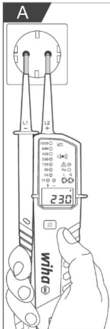
50 ○ Shows the measured voltage. In case of a 230 V socket, for example, the LEDs 24 ○ are illuminated up to 230. The following voltages can be displayed by the LEDs: 12, 24, 50, 120, 230, 400, 690, 1,000 V.
LC display
Symbol lights up when the battery is low.
0000 Shows the measured value.
HOLD The data hold function is activated.
v Symbol lights up if voltage is measured.
For your safety
Proper use
The device is used to test alternating electric fields. The device is solely intended for the applications described in these instructions, such as tests of voltage, single-pole phases, rotational field, flow and diodes. The device may only be used in the indicated nominal voltage range and in electric systems up to 1,000 V AC / 1,500 V DC.
Proper use also includes compliance with all information provided in these instructions. Any use beyond and differing from the proper use is considered improper use.
Improper use
- If the test tips L1- ⑭ or L2+ ② are bent do not continue to use the device.
- Use the test tips L1- or L2+ exclusively for testing voltage.
- Do not use the device's indication signals for measurement purposes.
User requirements
Permissible users are electrical specialists or expert persons who are accordingly trained and who are aware of the risks associated with operating the device and how to avoid them.
Only persons who can be expected to implement their work reliably are permissible as users. Any persons, whose reactions are influenced by substances such as drugs, alcohol or medications, are not permissible.
Based on their training, knowledge and experience as well as knowledge of the applicable standards and regulations, users are capable of carrying out work involving the device professionally and safely. In addition, users are capable of independently recognising and avoiding the risks involved with this work.
Residual risks

The device is up-to-date technology and meets current safety requirements. Nevertheless, there are residual risks that require careful action.

Danger of injury from improper handling of batteries!
With improper use, batteries may explode or liquids that are harmful to health may seep out. Coming into contact with battery liquid may lead to injury and death.
- Never try to charge the batteries.
- Do not short circuit the contacts "+" and "-" of the battery.
- Do not expose batteries to moisture or humidity.
- Do not change the shape of the batteries, do not open or disassemble batteries.
- Keep batteries away from hot environments.
- If skin comes in contact with seeping liquid, thoroughly rinse the affected area with water.
- If seeping liquid comes into contact with eyes, rinse eyes with clean water and contact a physician.
- If you swallow seeping liquid, rinse your mouth, drink plenty of water and contact a physician. Do not induce vomiting.

Mortal danger from electric voltage!
Coming in contact with live parts constitutes immediate mortal danger from electric shock.
- If the insulation is damaged, immediately disconnect the device and do not continue to use the damaged device.
- Do not carry out repairs independently on the device. Instead, contact customer service.
- Keep the device away from moisture and humidity to prevent a short circuit.
Before use
Safety before use

- Before each use test that the device is working with no problems by checking a known voltage source, e.g. a 230 V socket. Check for cable breaks and seeping batteries.
- During use, hold the device using the grips provided for this purpose. Never touch the test tips L1-① and L2+② and do not cover the LED display ⑬ or LC display ⑦.
- Keep the device away from moisture, humidity and explosive environments.
- Ensure the batteries are working before to each use 10 and replace them if needed.
- Do not use the device if the battery compartment is open ⑨!
- If your safety is no longer assured, switch off the device and secure against use. Safety is no longer assured in the following cases, for example:
- The housing 12is broken or there are cracks in the housing.
- The device no longer carries out the required tests without error.
- The device was stored for too long in poor conditions (see section on „Transport and storage“ on page 13).
• The device was damaged during transport.
OPERATING INSTRUCTIONS
• Liquid is seeping from the batteries.
- The cables on the device are damaged.
- Only use the device at ambient temperatures of 5 to +40 °C and a maximum relative humidity of 85%. This is the only way to guarantee precise measurement values.
- In the case of loud background noise, make sure that the acoustic signal from the device is audible.
Depending on the interior impedance of the voltage tester, in case of noise voltage there are different options for the display "operating voltage available" or "operating voltage not available".
- A voltage tester with relatively low interior impedance will not display all noise voltages with an original value above ELV compared to the reference value 100 kΩ. When in contact with the system components to be tested, the voltage tester can temporarily lower the noise voltage by discharging down to a level below ELV, however, after removal of the voltage tester the noise voltage will resume its original value. If the display "voltage present" does not appear, we strongly recommended that an earthing system is installed prior to commencing work.
- A voltage tester with relatively high interior impedance will not clearly display all noise voltages with the noise voltage "Operating voltage not present" compared to the reference value 100 kΩ. If the message "voltage present" is displayed for a part that is considered detached from the system, we strongly recommended that you use additional means (e.g. a suitable voltage tester, visual inspection of the detachment point from the electrical grid, etc.) to verify the state "operating voltage not present" of the system part to be tested and to determine that the voltage displayed by the voltage tester is noise voltage.
- A voltage tester that displays two values of interior impedance has passed the test of its suitability for handling noise voltage and is capable (within the technical limits) of differentiating operating voltage from noise voltage and displaying the existing voltage type directly and indirectly.
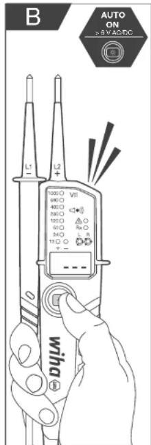
Auto power on/off
Auto power on
- The device and the measuring point illumination ③ switch on automatically when there is voltage above approx. 6 V AC/DC present, or with single-pole phase testing of the test tip I 2+ (2).
- If you push the [ ] ⑧ button, the device and the measuring point illumination are switched on.
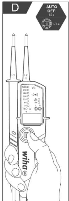
Auto power on/off
- The device and the measuring point illumination ③ switch off automatically after 30 s if the test tips L1-⑭ and L2+② do not receive a signal.
- You can also manually switch off the device and measuring point illumination. To do this, press the [★] ⑧ button for longer than 6 s.
Self test
The device has a self test function to ensure your safety. The self test verifies the functioning of all LEDs on the LED display ⑬, all symbols on the LC display ⑦, the acoustic signal and the measuring point illumination ③.

Carry out a self test prior to and following every use to ensure the functionality of the device.
Proceed as follows:

Do not carry out voltage tests while the self test function is active!
- Switch the device off by making sure that the test tips
L1- ^14 and L2+ ^2 are not receiving any signal. The device and the measuring point illumination will switch off automatically after 30 s.
You can also manually switch off the device and the measuring point illumination. To do this, press the [★] ⑧ button for longer than 6 s.
- Close phases L1- and L2+ by holding the two test tips L1- and L2+ to each other.
All LEDs, all symbols on the LC display and the measuring point illumination are illuminated. The acoustic signal is actuated for 3 s.
-
If all or individual LEDs as well as symbols on the LC display or the measuring point illumination are not illuminated or the acoustic signal is not actuated, the device cannot be used safely. Change the batteries (see section on „Replacing batteries“ on page 13) and restart the self test.
-
If the self test fails again, the device is not safe and may not be used. Contact customer service (see section on "Service and warranty" on page 14).

When you replace the batteries, the self test starts automatically.
Operation
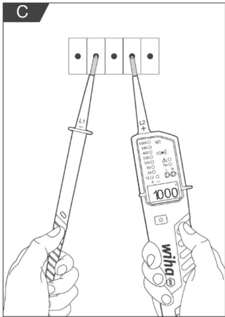
Voltage test
-
Hold both test tips L1-⑭ and L2+② to the object to be tested.
-
The voltage is displayed by the LEDs and on the LC display ⑦.
- If the voltage exceeds 50 V AC / 120 V DC an acoustic signal is also triggered.
• The voltage polarity is indicated as follows:
AC: LED + and -12 V light up - DC: LED +12 V light up
- DC: LED -12 V lights up and "-" appears on the LC display
- If there is negative/positive voltage on the test tip L2+, then a -/+ is displayed on the LC display.

During the voltage test, the LED L or R may light up.
When fixed in place, the test tips L1- and L2+ are the same distance apart as the contact openings of a socket, i.e. testing can be carried out with one hand.
Single-pole phase test

Testing of an electric circuit must not rely solely on this single-pole phase test. Carry out an additional voltage test to achieve a precise result.
It is potentially not possible to obtain a precise measurement if the insulation/earthing conditions of the user or the tested object are insufficient, for example if the floor is insulated or surfaces are painted.
- Hold the test tip L2+ ② to the object to be tested.
The ELV LED is illuminated. An acoustic signal is actuated if the voltage exceeds approx. 100 V AC.
Rotation field test

LED L and R can be operated with different wire systems, however, you can only obtain a precise test result with a three-phase alternating current four-wire system.
It is potentially not possible to obtain a precise measurement if the insulation/earthing conditions of the user or the tested object are insufficient, for example if the floor is insulated or surfaces are painted.
The device detects the incremental phase sequence with reference to use as the earth.
- Fully grasp the handles to ensure capacitive coupling to earth.
- Hold both test tips L1- (14) and L2+ (2) to the object to be tested.
The voltage from phase to phase is displayed by the LEDs:
LED R is illuminated in case of right rotation.
LED L is illuminated in case of left rotation. - Now carry out a counter-test with replaced test tips L1- and L2-. The rotation direction must always change.
Flow/diodes test
- The object to be tested must have zero voltage.
For this purpose carry out a voltage test (see section on „Voltage test“ on page 12). - Switch the device on by holding both test tips L1- ⑭ and L2+ ② to each other or pushing the button [ ] ⑧.
- Hold both test tips L1- and L2+ to the object to be tested.
In case of flow (up to approx. 500 kΩ) the LED Rx is illuminated and an acoustic signal is actuated. If no flow is detected, the device switches off automatically after approx. 30 s.
If the device is switched off and a flow is detected, the device switches on again automatically.
For diodes, the LED Rx is illuminated and an acoustic signal is actuated when L1- is connected to the anode and I2+ to the cathode. If the device is connected in reverse order to the diode, no flow is shown.
OPERATING INSTRUCTIONS
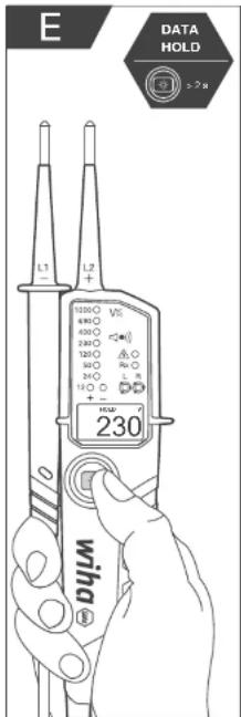
Data hold function
In the data hold mode, the LC display ⑦ of the device only shows the most recently stored measurement value. In the data hold mode, the LC display does not update, regardless of whether the device is connected to a live or voltage free object. The LEDs always show the currently measured voltage, even if you are in data hold mode.
- To activate the data hold function, press the [ * ] ⑧ button for longer than 2 s. An acoustic signal is actuated and the most recently measured value along with the symbol "HOLD" are shown on the LC display.
- To deactivate the data hold function, press the [☐] button again for longer than 2 s. An acoustic signal is actuated.
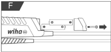
Replacing batteries
i Make sure that the device is voltage free before replacing the batteries. To be sure, carry out a voltage test (see section on „Voltage test“ on page 12).
The batteries ⑩ must be replaced under the following circumstances:
• The flow test can no longer be carried out successfully.
- On the LC display, ⑦ the symbol lights up.
- Loosen the screw on the battery compartment lid ⑪.
- Remove the battery compartment lid.
- Remove the two dead batteries and dispose of them in an environmentally responsible manner (see section on „Disposal“ on page 13).
- Insert two new batteries (1.5 V A/V) into the battery compartment ⑨. When inserting the batteries, observe the correct alignment according to the marking on the battery compartment.
- Screw the battery compartment lid back on.
Make sure that the battery compartment is closed prior to every use. When you replace the batteries, the self test starts automatically (see on „Self test“ on page 11).
After use
Care
- Switch the device off before any care work and make sure that the device is voltage free.
- Clean the device regularly by wiping it down with a slightly dampened cloth.
- Do not use any scouring agents or solvents.
- Keep the grip surfaces dry, clean and free from oil or grease.
- Verify regularly that the device and the accessories function as intended and do not jam, and that they are not broken or damaged.
Transport and storage
- Do not expose the device to direct sunlight, high temperatures or humidity.
- Remove the batteries when you are not using the device for an extended period of time, or when you are transporting or storing it.
Disposal
Improper disposal is hazardous to the environment! Improper disposal can result in danger to the environment. - Remove the batteries before disposing of the device. - Do not dispose of the batteries and the device with general waste. - I have approved specialists dispose of electric scrap and electronic components. - In case of doubt, consult your local municipal authority or specialised disposal companies regarding environmentally responsible disposal.
Maintenance and troubleshooting
- The device requires no additional maintenance if used according to the instructions.
- Should the device no longer work, contact an authorised customer service point for Wiha power tools.
- If the test tips L1- and L2+ are bent, do not continue to use the device under any circumstances!
- Remove the batteries when you are not using the device for an extended period of time, or when you are transporting or storing it.
- Have damaged parts repaired before use.
- Do not correct issues yourself!
- State the article number according to the nameplate (see section on "Nameplate" on page 14) of your device for all inquiries and spare part orders.
- For additional information regarding repair and maintenance, exploded drawings and information about spare parts, visit: www.wiha.com
Service and warranty
Should the device no longer work, should you have any questions or require information, contact an authorised customer service point for Wiha power tools:
Customer care
Germany Website: www.wiha.com
GERMANY
The warranty is voided in the event of injury or damage to property caused due to non-compliance with these instructions. The manufacturer accepts no liability for consequential damage!
Technical specifications
Display 13 LEDs, 4-digit LC display
Background illumination Yes
Polarity display automatic
Voltage range ± 12/24/50/120/230/400/690/1,000 V
12-1,000 V AC / 12-1,500 V DC
Frequency measurement range 40–400 Hz
Input current ≤ 3.5 mA (690 V AC)
≤ 6 mA (1,500 V DC)
Single-pole phase test 100–1,000 V AC
Rotation field test 170–1,000 V
Acoustic and visual flow/diode test 0–500 kΩ + 50%
Excess voltage category CAT IV 1,000 V
Protection class IP64
Standard EN 61010-1, EN 61243-3:2014
Data hold Measured voltage value
Auto power on/off Yes
4 mm test tip adaptor screw-on
Dimensions (LxWxH) 240 x 75 x 30 mm
Weight approx. 270 g
LED display (ELV) > 50 V AC / > 120 V DC
Response time of LED display 1 s
(at 100% nominal voltage)
Precision of the LCD ± 3% ± 3 digit
(± 6 1,000 V AC / 6 1,500 V DC)
LCD resolution 1 V
LCD out of range indication OL
Peak current ≤ 3.5 mA (at 1,000 V)
Measurement duration 30 s ON/operating time,
240 s OFF/recovery time
Internal battery use approx. 80 mA
2x battery 1.5 V AAA / IEC LR03
Operating temperature -5 to +40 °C
Storage temperature -20 to +70 °C
Max. relative humidity 85%
Max. height for voltage testing 2.000 m
Contamination level 2
Cable length approx. 1.2 m
Nameplate
The nameplate is on the rear of the device.

BEDIENINGSHANDLEIDING
Inhoudsopgave
Auto Power On/Off 25
+ DC: led +12 V brandt
(± 6-1000 V CA / 6-1500 V CC)
Resolución LCD 1 V
Auto Power On/Off 39
Autodiagnosi (autotest) 39
Utilizzo 40
Prova tensione 40
Test fase monolase 40
Test campo rotante 40
Auto Power On/Off 46
Egenkontrol (solvtest) 46
Betjening 47
Spændingstest....47
Etpolet fasetest 47
Drejefelttest 47
Gennemgangs-/diodetest 47
Apparatets bagside (typeskilt)

Auto Power On/Off 53
Egenkontroll (solvtest) 53
Betjening 54
Spenningstest 54
Enpolet fasctest 54
Driefelttest 54
Apparat for arboid under spenning.
Auto Power On/Off 60
Auto Power On/Off 67
Itsotarkistus (itsotosti) 67
Käyttö 68
Jännitetarkastus 68
Auto Power On/Off 74
Samokontrola (autotost) 74
Obstuga....75
Test napięcia....75
Obsah
O tomto návodu 78
AC: svití I FD diody + a -12 V
Auto Power On/Off 95