45216 - Measuring equipment Wiha - Free user manual and instructions
Find the device manual for free 45216 Wiha in PDF.
Frequently Asked Questions - 45216 Wiha
User questions about 45216 Wiha
0 question about this device. Answer the ones you know or ask your own.
Ask a new question about this device
Download the instructions for your Measuring equipment in PDF format for free! Find your manual 45216 - Wiha and take your electronic device back in hand. On this page are published all the documents necessary for the use of your device. 45216 by Wiha.
USER MANUAL 45216 Wiha
Batterie 3 V (IEC LR03 1.5 V x 2)
Temperatur -15...50 °C Betrieb; -20...60 °C Lagerung, Keine Kondensation
Website: www.wiha.com
References marked on tester or in instruction manual
Warning of a potential danger, comply with instruction manual.
i Reference. Please pay utmost attention.
Caution! Dangerous voltage. Danger of electrical shock.
Equipment for working under live voltage.
Continuous double or reinforced insulation complies with category II DIN EN 61140.
CE Complies with EU specifications.
UK Complies with UK specifications.
Tester complies with the standard (2012/19/EU) WEEE.
The instruction manual contains information and references, necessary for safe operation and maintenance of the tester. Prior to using the tester (commissioning/ assembly) the user is kindly requested to thoroughly read the instruction manual and comply with it in all sections.
Failure to read the tester manual or to comply with the warnings and references contained herein can result in serious bodily injury or tester damag. The respective accident prevention regulations established by the professional associations are to be strictly enforced at all times.
Introduction
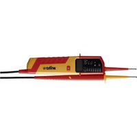
The voltage tester 45216 is universally applicable tester for voltage testing, continuity testing, rotary field testing and trip test of RCD.
The voltage tester 45216 is characterized by the following features
Designed to meet international safety standards IEC 61243-3:2014
Measurement category (CAT.) IV 600 V, III 1,000 V
- AC and DC voltage test up to 1,000 V AC and 1,500 V DC
- Polarity indication
- Single-pole phase test
- Phase rotation test
- Trip test of RCD
Continuity test
- Auto Power ON / OFF
- Torch light
IP64 (IEC 60529)
Vibration motor
After unpacking, check that the instrument is undamaged. The product package comprises
1x Tester 45216
- 2x4 mm test tip adapters
- 2x CAT III/1,000 V test tip cover
- 2x Batteries 1.5 V (AAA, IEC LR03)
- 1x Instruction manual
Safety measures

The testers have been constructed and tested in accordance with the safety regulations for voltage testers and have left the factory in a safe and perfect condition. To maintain this condition, the user must observe the safety instructions in this manual.

The operating instructions contain information and References required for safe operation and use of the tester. Before using the tester, read the operating instructions carefully and follow them in all respects.
Danger of electric shock and other dangers

To avoid an electric shock, observe the precautions when working with voltages exceeding 120V (60 V) DC or 50 V (25 V) eff AC. In accordance with DIN VDE these values represent the threshold contact voltages (values in brackets refer to limited ranges, e.g. in agricultural areas).

The tester must not be used with the battery compartment open.

Before using the tester, ensure that the test lead and device are in perfect working order. Look out e.g. for broken cables or leaking batteries.

Hold the tester and accessories by the designated grip areas only, the display elements must not be covered. Never touch the test probes.

The tester may be used only within the specified measurement ranges and in low-voltage installations up to 1,000 V AC / 1,500 V DC.

The tester may be used only in the measuring circuit category it has been
designed for.

Before and after use, always check that the tester is in perfect working order (e.g. on a known voltage source).

The tester must no longer be used if one or more functions fail or if no functionality is indicated.

It is not permitted to use the tester during rain or precipitation.

A perfect display is guaranteed only within a temperature range of -15^ to 50^ at relative air humidity less than 85% .

If the safety of the user cannot be guaranteed, the tester must be switched off and secured against unintentional use.

Safety is no longer guaranteed e.g. in the following cases
- obvious damage
- broken housing, cracks in housing
- if the tester can no longer perform the required measurements/ tests
- stored for too long in unfavorable conditions
- damaged during transport
leaking batteries

The tester complies with all EMC regulations. Nevertheless it can happen in rare cases that electric devices are disturbed by the electrical field of the tester or the tester is disturbed by electrical devices.

Never use the tester in explosive environment.

Tester must be operated by trained users only.

Operational safety is no longer guaranteed if the tester is modified or altered.

The tester may be opened by an authorized service technician only.

If the indication "voltage present" appears although the checked part is considered as disconnected, it is recommended to verify additional measures if the measured voltage is an interference voltage or not.
Intended use
The tester may be used only under the conditions and for the purposes for which it was designed. Therefore, observe in particular the safety instructions, the technical data including environmental conditions.
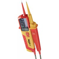
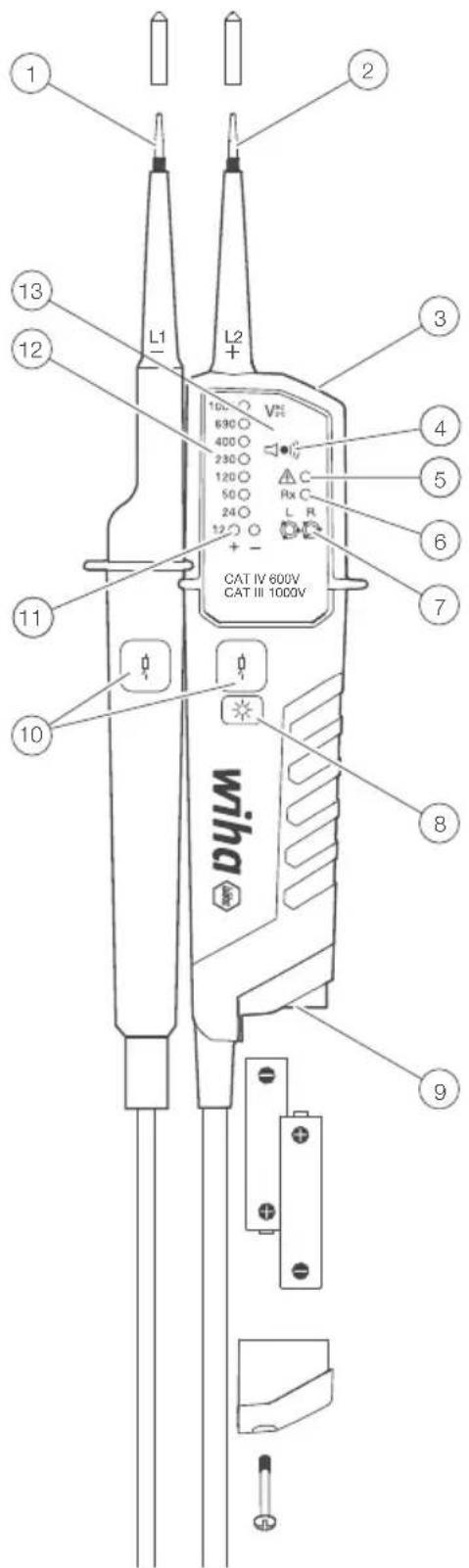
Tester information and control elements
Test tip, L1
Test tip, L2
3 Torch light
4 Buzzer hole for acoustic indication
Single pole test ELV warning
6 Continuity test
7 Rotary field
8 Torch light button / Activation R-measurement
9 Battery door
10 Trip TEST RCD pushbuttons
11 LED's indicating 12 V and polarity
(12) Voltage indication
13 Display
Accessory
- 4 mm test tip adapters
Plug on cover (GS38) - Protective cover
Preparation for tests
Auto Power On / Switching On
- The tester switches on when it detects continuity, an AC or DC voltage above approx. 12V or a live phase on L2 (single pole test).
- It can be switched on with the torch light button.
Auto Power Off
- Tester is automatically powered off after 30 sec when there is no signal contacted to the probes.
The torch light switches off after approx. 30 sec.
Self-test
- When voltage tester is off short both probes L1 and L2, hold probes shorted.
- All LEDs, vibration motor and buzzer will be on for 2 s.
- Self-test will start automatically when replacing batteries..

If some of LEDs is not ON, or buzzer or torch light is not ON, the device is not safe for use. Replace the battery and start Self-test again. If some of these indications are not ON again, the device is not safe for use and must NOT be used.

Do not use tester while Self-test procedure is activated.
Conducting tests
Voltage test
- Connect both probes to the object under test.
- The voltage is indicated by LEDs.
- Buzzer sounds and vibration motor is on when a threshold voltage of 50 V AC or approx. 120 V DC is exceeded.
Voltage polarity is indicated in following manner.

AC: + and - 12 V LED are on

+DC: +12 V LED is on

-DC: -12 V LED is on (and " -" is shown on LCD)

When the L2 probe + is the positive (negative) potential, the polarity indication LED indicates +DC (-DC).

During voltage test, L or R LED may light up.

In case of empty batteries, the ELV LED lights up >50V AC/DC, >120V AC/DC.
Single-pole phase test

Function of this test may not be fully achieved if the insulation condition/ grounding conditions of user or of the equipment under test aren't good enough. Verification of live-circuit shouldn't be dependent on this Single-pole phase test only, but on the voltage test.
- Hold the tester well in your hand. Connect the "L2 +" probe to the object under test. Single pole LED lights up and buzzer sounds when a voltage of approx. 100 V AC or more exists in the object under test. (Pol ≥ 100 V AC).
INSTRUCTION MANUAL
Phase rotation test
- L LED and R LED for Phase rotation test may operate on various wiring systems, but effective testing result can be obtained only on three-phase 4-wire system.
- Hold the tester good in your hand and connect both probes to the object under the test.
- Phase-to-phase voltage is indicated by voltage LEDs.
- R LED lights up for right rotary field.
- L LED lights up for left rotary field.
- Measurement principle: The instrument detects the phase rising order regarding the user as earth.

Function of this test may not be fully achieved if the insulation condition/ grounding conditions of user or of the equipment under test is not good enough.
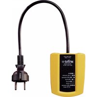
Trip test of RCD

For voltage tests in systems with RCD (earth leakage circuit breakers) an RCD can be tripped with a 10mA or 30mA nominal leakage current on single phase AC 230V power system.
- Connect probes "L1" and "L2" between L and PE of RCD protected system.
- Press simultaneously both of trip TEST RCD pushbuttons.
The RCD should trip.
Continuity test (Rx) / Diode test

The test circuit/object shall be de-energized before measurement.
- Check for the absence of voltage by conducting a two pole voltage test on the test object.
- Connect both test probes together or press the torch light pushbutton to switch ON the tester.
- Connect both test probes to the test object. For continuity (up to approx. 500k ) the continuity test LED - Rx is on and the buzzer is active.
- Continuity test automatically switches OFF after approx. 30 seconds if no continuity is detected. When tester is OFF, If continuity is detected it will be automatically switched on again.
Torch light
- Pressing the torch light button will turn on the light and after approx. 30 s it will turn itself off.
- When torch light is on, pressing the torch light button for more than 6 s will turn off the torch
Battery replacement

Remove the probes from any testing point, when opening the battery case. Batteries are empty when the continuity test with both test probes connected cannot be done anymore. A battery symbol in the LCD indicates low battery.
Follow the procedure below and replace batteries with new ones (type IEC LR03 1.5 V).
- Unscrew the battery door using Philips type screwdriver.
- Pull out the battery door and replace the batteries. Insert new batteries according to the engraving on the battery door.
- Re-assemble battery door.

Confirm that the battery door case is properly locked prior to measurements.
Technical data
Voltage range 12...1,000 V AC (16 2/3...950 Hz), 12...1,500 V DC)
LED nominal voltage 12/24/50/120/230/400/690/1,000 V, AC (16 2/3...950 Hz), DC(±)
LED tolerances according to EN 61243-3
ELV indication LED > 50 V AC, > 120 V DC
Response time < 0.5 s at 100% of each nominal voltage
Peak current Is < 3.5mA (at 1,000 V)
Measurement duty 30 s ON (operation time), 240 s OFF (recovery time)
Internal battery consumption approx. 80mA
Single-pole phase test voltage range 100...1,000 V AC (40...70 Hz)
Phase rotation test 170...1,000 V phase-to-phase, AC 50/60 Hz
Continuity test detection range 0...500 kΩ + 50 %
Battery 3 V (IEC LR03 1.5 V x 2)
Temperature -15...50 °C operation; -20...60 °C storage, No condensation
Humidity max. 85% RH
Altitude up to 2,000 m
Overvoltage CAT. III 1,000 V / CAT. IV 600 V
Standard EN 61243-3:2014
Pollution degree 2
Protection IP64
Cleaning and storage

Tester does not need any special maintenance if used according to user manual.

Remove tester from all test points before cleaning.

Use a lightly damp cloth with neutral detergent for cleaning the instrument. Do not use abrasives or solvents. After cleaning, do not use the device until it is completely dry.

Do not expose the instrument to direct sun light, high temperature and humidity or dewfall.

Remove batteries when the instrument will not be in use for a long period to prevent danger or damage due to possible battery leakage.
INSTRUCTION MANUAL
Safety advices
- Depending on the internal impedance of the voltage detector there will be a different capability of indicating the presence or absence of operating voltage in case of the presence of interference voltage.
- A voltage detector of relatively low internal impedance, compared to the reference value of 100k will not indicate all interference voltages having an original voltage value above the ELV level. When in contact with the parts to be tested, the voltage detector may discharge temporarily the interference voltage to a level below the ELV, but it will be back to the original value when the voltage detector is removed.
- When the indication "voltage present" does not appear, it is highly recommended installing earthing equipment before work.
- A voltage detector of relatively high internal impedance, compared to the reference value of 100k may not permit to clearly indicate the absence of operating voltage in case of presence of interference voltage.
- When the indication "voltage present" appears on a part that is expected to be disconnected of the installation, it is highly recommended confirming by another means (e.g. use of an adequate voltage detector, visual check of the disconnecting point of the electric circuit, etc.) that there is no operating voltage on the part to be tested and to conclude that the voltage indicated by the voltage detector is an interference voltage.
- A voltage detector declaring two values of internal impedance has passed a performance test of managing interference voltages and is (within technical limits) able to distinguish operating voltage from interference voltage and has a means to directly or indirectly indicate which type of voltage is present.
Service and warranty
Should the device no longer work, should you have any questions or require information, contact an authorised customer service point for Wiha power tools:
Customer care
Wiha Werkzeuge GmbH
Obertalstraße 3-7
78136 Schonach
GERMANY
Tel.: +49 7722 959-0
Fax: +49 7722 959-160
Email: info.de@wiha.com
Website: www.wiha.com
The warranty is voided in the event of injury or damage to property caused due to non-compliance with these instructions. The manufacturer accepts no liability for consequential damage!
MODE D'EMPLOI
Introduction 4
Spcifications techniques 9
Site Web: www.wiha.com
Egnet for arbeid under spening.
Lamplig for arbete under spanning.
Kontinuereg dubbel erler forstärkt isolering enligt kategori I DIN EN 61140
Uppfyller EU-krav.
Akku 3 V (IEC LR03 1,5 V x 2)
Yka3aHnHa TecTep HanpJxKeHHN B INHCTpyKcH

Octopokhnoctb!IpeynpejxdeHne 6o anachoi ToKe,co6nlaTe HNCTpykunIO no 3KcnpnyatauIN.

YBeDMJIeHHe. IoxaanyIcTa, O6paTInTe BHIMMaHHe.

OctopoxHocTb! Onachoe HapxKeHne, pCK npaxKeHna 3JektpuecknM TOKOM.

POnxOoNITnIpaObTI npHapJxHeHEm.

HnpebBnaI BOnHnA nn yCnneHHa n3OJIaB B COOTBeTCTBn C KaTeOpne II DIN EN 61140

COOTBETCTByET Tpe6oBaHnM EC.

COOTBECTBYETpe6oBaHnMBeNkO6pntAHn.

YcTpoIcTBo COOTBETCTBye TdUpeKtNBWe WEEE (2012/19/EU).

HCTpyKuIN NO 3KcIyataCn COepKaT INDopMaUIO INHCTpyKUIN, HEO6xOIMbIE DnA 6e30aChOH 3KcIyataUIN N CNOJb3OBaHIN yCTpOInCTBa. IpeE INCNoJIb3OBAHHem ycTPOINCTBa Heo6XoIMBO BHMAtelbHO npOHTaTB INHCTpyKUIN NO 3KcIyataUIN CNEIOBaTb EIN BO BCEX OTHOWENIX.

HecobJIOHeHne HNCTpyKUIN HecoBLOJeHne npEdupeXKeHn IN npIMeuaHm MOKeT pInBeCTn K ONaCHbIM DJIa Xn3Hn TpaBMam Nolb3ObaTeJIa n IOBpeKDeHIO yCTpOInCTBa.
BctynJIeHne
TecTeHnApJxHeHn 45216 npedctabIaET cO6o yHnBepcaJIbHbI TeCTep HAnpJxHeHn C npOBepKoHnPaBnEHHBpaUaIOUeOcRIOJI, npOBepKo HnpePbIBHOCTN, npOBepKo OHNOpIoCHOn fo3bl N npOBepKo CpAbTaBHaHHa 3aUHTHO YoCTPOIcTBa FI/RCD. TectepbHnApJxKeHHuN3rOToBJIeHbI B COOTBetCTBm C nocJeHIMn npAByIaMm TexNHKn Be30NaChOCTn I oBeCneHuBt 6e30NaChyIO n HaDeKHyo pa6Otu.
TecTe HapnKeHn 45216 xapaKTepeN3yeTc cJeDyUOUMM MOMeHTaM
-ПocТpoEнВ COOTBETCTBmCO CTaHДapTOM IEC 61243-3:2014.
- Kateropnna n3mepenra (CAT.) IV 600 B, III 1000 B
- IVcNbItaHne NoCToHHbIM n nepemehhbIM HapjxKeHnEM do 1000 B nepemehHoro ToKa n 1500 B NoCToHHoro ToKa
-Индikatop поларноctи
- OdHOrOJIIOHcHbIΦa3OBbI TECT
- DByxNIOHCHOe ONpeJeIeHHe YpeEOBaHnApa3 OTHOCHTeJIbHO 3EMNI
- IVcnbTaHHe Ha cpa6aTbIBaHHe yCTPOiCTB 3aUHTbI OT TKOB yTeKn Ha 3eMnIO
- NcblTaHHe Ha HenpepeBIBHOCTb
- ABTomATnHECKOE BkJIIOueHHe N BbIKJIIOueHHe
OcBeueHHe ToKn N3MepeHnC NOMoUbIO BeNoTO CBeToDnOda
IP64 (M3K60529)
Bn6paonHHbI DnVraTeIb
Pocne pacnakOBKn npOBepbTe ueIOCTHOCTb yctponCTBa. BxOaNT B noCTABky
- 1x TeCTep HaprrkHeHr 45216
2 aanTepa TectoBOrHaKoHeuHnka 4 MM
2x3aunTaNCbIraTeJIbHOro HakoHeuHnKa CAT III/1000 B
26aTapeuKn 1,5B (AAA,IEC LRO3)
1xpykoBOCTBOIolb30BaTeTn
MepbI npedocTopoXHocTn

TeCTepbHnpanjxHn6bnnn3rTOBHeBIB COOTBETCTBNC npabnilamn
TexnKn 6e3oNaChOCTn DnT TeCTepOB HnpanjxHn, nPOBepeHb N OTnpaBHeBc 3aBOda B nDeaJIbHOM COCTOHaHm C TOUKN 3peHn 6e3oNaChOCTN. nn
noIepKaHnE TOTO CoCTOHaHn NOJIb3OBaTeJIb DOJXeH cO6IHOaTa b NHCTpyKuNN
IO Texnke 6e3oNaChOCTn, CoedePkaUneCeB DAHHOM pyKOBOdCTBe.

HCTpyKUIN NO 3KcIyatauIN COePkaT INHOpMaUNIO INHCTpyKUIN, HEO6xOIMbIE DnIg 6e30aChOH 3KcIyatauIN N IcNOJb3OBaHIN yCTpOInCTBa. Ipeep nCNoJIb3OBaHNEM yCTpOInCTBa Heo6xOIMBO BHMATEJIbHO npOHTaB INHCTpyKUIN NO 3KcIyatauIN CNeIDOBaTB eN BO BCEX OTHOHeHIX.
Pnck npaxkeHna 3JIeKtpnueckm TOKOM n dpynx onachocte

Bo n36eKaHHe nopaxKeHHa 3JIeKTPnueCKHM TOKOM Heo6xOJIMo Co6JIHOdaTb MebpI npedOctOpoxHoCTn npu paBote c HapnxKeHHem Bblue 120 B (60 B) noctoHHoro ToKa nn50 B (25 B) cpeHekBaJpaTHoro 3HaueHHa nepemEHoro ToKa. Cornacho DIN VDE, 3TN 3HaueHHa npedCTabJIOT C6oB npedeJIbHbIe HapnxKeHHa,do KOTobix eue MoXHO npiKacaTbc8 (3HaueHHa B CKO6kax OTHocTcR K 3OHAM C ORpAHueHHbIM DOCTyPOM, HApNIMep, K CeJIbCKOXO3raCTBeHHbIM yTOdbam).

TecTeP HanpXeHn HeIb3a IcNoJIb3OBaTb, KOrJa aKKyMylrTopHaR KOHHaTa OTKpbITA.

PepaKaKdbIMNCbITAHmE yBeaNTecb,yTO n3MePeHTeBHaJINHNA
I3MePnTeBHOeYCTPOJCTBO HAXOJTCB INeAaHbOM COCToHIN. O6paTne BHMaHHe Ha 06OpBaHHbIe KaEJI NII, BO3MOXHO, IpOTekaIOUme BaTapeN.

PnPKacTaBc K yCTpOncTBy u akceccyapam MoXHO TOnbKO B CneUaNbHO OTBeHeHbIX MecTx, 3JIeMeHTb IINCPIIe He DoJxKbI 6bITb 3aKpbITb. PnIIO6bIX O6CToRrTeBCTBax CNeIyEt N36EgAtb PnIKOCHOeHnK T ETOBIM HAKOHeYHnKAM.

Be3onacnoctb 6oIbIe He rapaTnpyETc
OueBvHoe NOBpeKdHeHc
TpeunHbI nn npytne nobpeckdneHn Kpnpca
- ecJIN yCTpOJCTBO 60JIbIe He BbIIOJHReT KeJaEMbIe N3MepeHry/TeCTbl
CINUKOM DInTEJIbHOE IN HeBnaorponpHtble ycIOBnXpaHEHn
-Повөхдөнгь, Визвангье Трансларпогько усточтб.
- pnoTeKaIOUne 6aTapei

YcTpoIcTB COOTBETCTByET BCem Tpe6oBaHnM EMC.TEm He MeHee, B OueHb peKnx CnyaX MoKeT CnyuHTbcra TaK, YTO TecTep HApJxKeHn IIN TeCTep HApJxKeHn 6yDyT BO3MyuTaB Dpyrne 3JeKtpnueckne yCtpoIcTBa.

Hikorda He nCnojIb3yIte yCTpoiCTBO BO B3pbboONaCHO cpeJe.

YCTpOJCTBO MOKET MNOJIb3OBaTbCra TOJIbKO OByeHHbIM NepcHajOM.

3KcIpyatauHnHa 6e3oNaCHocTb 60JIbUe He rapaHTnpyETcB CJIyuae MoDnФkaCm nnn nepeOobopyoBaHna.

YCTPOIcTBOMOKeTOTKpbIBaTTOJIbKOaBTopN3OBaHHbIMCNEUaJINC T0 06CJyXuBaHnIO.

EcIINoBnIeTcOo6UeHHe“HanpJKeHne npCytCTByeT”,XOTIPOBepEmaaCTb CHTaETcOTKJIIOUeHHoOT CNTEmbl,HaCTOReTbHOpeKOMeHnyETcNtEM DOnONHInTeJBhBix N3MepeHn ONpeJeINTb,Bbl3BaHO IIN3MepeHHoe HanpJKeHne HanpJKeHem NOMexnnHET.
PYKOBODCTBO NOJb3OBATEJIa
IcnoJb3OBAHHe nHa3HaueHnIO
YcTPOIcTBMOKHOICNOLb3OBaTbTOJIbKOBTexycIOBnXINJITEXCEJIe,JIKOTOpbIXOHO6blno pa3pa6oTaHO.Yka3AHnI NO TExHnke 6e3oNaCHOCn,TEXHnueCKneDaHHBe INyCIOBnOKpyKaUcEcnpeblDOnJXHbCo6IIOdaTbcB OOCoBeHNOCTn.
3IeMeHTbI ynpabJeHnI n dncnne
1 Tectobn HakoHeuHK, L1
2 Tectobn HakoHeuHK, L2
3 OcbelueHne ToKn n3mepeHn
OTBepCTneIIN3xONOTA
5 Tect OndHonoIocHO pa3bl, npedynpeXdHne 6 onaCHOM Hapjxehn
6 Ncnbirahme Ha HenpepbBHOCTb
7 DmCnneBpaauoUIMcnoJeM
8 KhoNka noCDCBETKn TOkNn3MpeHnA/akTINBaunR-Test
9 BaTapeHbI OTeCk
10 KhoNKn OTKJIIOUeHnY3O
11 CBeToIIObI,IaI INHINKaUIM 12B I NOJIAPHOCTN
12 HndkaTOp HanpJKeHn
13 3KpaH

Akceccyapbl
AanTep TectoBOrHaKoHeuHnka 4MM
BtauHoi pykaB (GS38)
3aunTa HakoHeHHika
Ioprotobka K 3K3ameHaM
ABTOMaTnueckn nnn pyHOB BBOB 3KcPnyaTaCuIO
-ДeTeKTop HAnpЯЖeHЯ BKNIOHaTcR npn O6HApxJeHm HEnpepbHocTn, nepemEHHO rIN NOCToHHOrO HAnpЯЖeHЯ BblIe npimEpHo 12BnnnФa3bI c L2.
- PπiδoP MOKHO BKJIIOHHTB C NOMOULIO HO KHOIKN Ha NOIDCBETKE TOHKIN I3MEpeHNA.
ABTOMATNueeCKoe OTKJIOUeyHne
- Pnp6op aTOMaTHueeCKN OTKIOUaETc npMepHO uepe 30 cekyH,ecn Ha n3MepntelbHbIX yynax He oBhApyKnBaetc CnHaJ.
OcBeueHHe ToUKN N3MepeHnB BbIKIOaEaTcR TIPIMepHO Uepe3 30 cekyH.
CamonpoBepka
- CamOTeCTnObaHne HaunHaetc, KOrda TeCTep HapJxehnBbIKIOaETc, a Dba TECTOBbIX KOHTaKTA L1 n L2 3ambiKaIOTc HAKOpOTko.
Bce CBeToIOIObl, Bn6pOMOTOpbl n 3ByKObIe CNHJIbl BKIOUaIOTcra Ha 2 CEkyHdbI.
KordaBaTapeiKn BCTaBHeHb, CaMOnpOBePka HauHaTeCn ABToMaTuYeCKn.

EcnHekOTOpBie n3CBETODIOOB He 3aRopAOCTc, 3yMMep nnIPOHaNk He 3aropAOCTc, yCTpOJCTBO He6e30NAcHO dIy IcNOJIb3OBAHnI. 3aMeHNTe baTapeIO u CHOBA 3aNyCTnte camOpOBepky. Ecn HekOTOpBie n3 3tIXu INdkaTOPOB He 3aropAOCTc CHOBA, yCTpOJCTBO He6e30NAcHO n HE DOJNKHO nCnoJIb3OBAbCra.

He nCIOJIb3yIte TcTeP BO BpeM aKTHBHO CamOPIOBePK.
PpOBeJeHHe NcNbTaHn
IcnbitaHna paTaeKeHne
- PπρικΟCHITECb K ΚΙΜερρεΜΟΥ ΜθέβΚτγ ΤΕΤΟΒβΙΝ ΒυγαΜΙ.
- PpinyoxeHHoe HapryxHeHne OTo6paXaetc CBTeOIOJaAMn.
Pa3dactc3BykoBoCnHnI,INBnIaTeJIb Bn6paTopa BKnHOnTcR,KOrda 6ydt npEbyIeNo nporOoe HapJxKeHne 50 B nepemEnHoro Toka nn npn6n3ntelho 120 B noctoHHoro Toka.
-Плярноctb yka3bIbaeTcR cIeIyUOJIIM O6pa3OM.

AC: ropT CBTeOJIOJbI + n - 12 B

+DC:ropntCBeToDnO+12V

--DC: ropnt cBeToIIOID -12V (Ha KK-dncnnee oTo6paKaaeTcra «-»)

EcIn Ha TectOBbHn HakoHeHHK L2 noJaETcRn noIOXHTeJIbHbN nOteHuaI (OTpuataTeJIbHbN nOteHuaI), oTo6paKaETcRn +DC (-DC).

CbeToIIOU Lnn R moKet 3arOpEbcra BO BpEm npOBepKn HnprKeHna.

Korda 6atapen paarjxhehi, npi > 50 B nepemehoro/NoctoHHoro Toka, >120 B nepemehoro/noctoHHoro Toka 3aropaetc Tolbko CBeToIOd «Onachoe HanpaxheHne>.
OdHONOJIIOCHbI Φa3OBbI TeCT

Pabota He rapaHTnpyETc, ecn ycnOBn 3a3emJeHnIoxHe. TecT OHHoNIOCHOn HaaBHeJIb3r IcNoIb3OBAbT dIg npOBepKn OTCytCTBnHapJKeHn.
Kperiko depknte Tectep HanpkaHnB pyke. POncoeHNHTe TectOBbl
PYKOBODCTBO NOJb3OBATEJIa
HaKoHeHnK L2 K TecTnpyemomy o6bekTy. CBeToIOIOv «TeCTnpOBaHne OHOHOIOCHOH pa3bl" 3aropaeTcN pa3daeTcN 3ByKOBo CNrHaN, KOrDa Ha TeCTnpyemom o6bekTe npCytCTbYeT HApJxehne>100 B nepeMeHHoro ToKa.
OdHONOLIOCHoe pa3OBoE nCbITaHne c BpaauoUcMcnoJeM
- IVcblTaHHe BpaAioUIMcra NOpem Daet HaJeKHbIe Noka3aHnra TOJbKO B npabINbHO 3a3EmHeHHbIX TpexPfa3HbIX CNTeMax.
Kpenko nepknte TceTep HnpanxeknB pyke. NoknOHTe TcTOBbI K TectnpemyOMy obBeKtY. - OTo6paKaetcMekdypa3Hoe HaprJKeHne
CBeToIOID R yka3bIbaeHa BpaueHne noI no YacOBn CTpeKe.
CBeToIOID Lyka3bIbaeHa BpaUeHne IOnI npOTuB YacBOB CTpeIKN.
-ПриицпиИЗмереня:Тecтep Hanряженя onpeДeЯET nopяДOK BOCXoxJdeHnja3Ha 3emJIIO.
Pa6ota He rapaHTnpyetcra, ecIn yCIOBna 3a3emHeHn nIoxne.
Tect OTKJIIOUeHnI H/UY3O
I JnnpoBepkn HnpanjKeHn B CnCTeMax c Y3O (abTomatom 3aunTHoro OTKIOUeHn) B OINHOpa3HOH CNCTeMe nepemehHORo TOKa 230 B MoKet cpa6aTbIBaTb Y3O C HOMHaJIbHbIM TOKOM yTeKn 10 MA INN 30 MA. Y3O DOJXHO cpa6oTaTb.
- PódklIOHnTe oBa TcTeObBix LUYa MExkDy L n PE.
- HaKMTe o6e KHOPIK RCD OJHOBPMeHNO.
- UCTPOINCTBO 3aunTHoro OTKJIOHHeHnI DOJXHO cpa6oTaTb.
PpOBePk HnpepbBnocTn (Rx) / npOBePk dnoDob
1 U6eHntecb, YTO oBBeKT NcblTaHn oBcToeH.
-IVcnoIb3ynteNCbItaHne DByXnIOJIOChbIM HappKeHHem,HTObbl y6eNTbcra, YTO NCbITyEmbI OBeKT ObECTOeH.
- PoiCoeHInHTe TcTeOBbIe HAcOHeuHNKn IIN HaKMNTe KHOKNy INHdNkTopa TOHKN N3MepeHnA, YTO6bl BKJIHOHTb TcTeTp.
- PoioceHInHe 6a TeCTOBbIX Uyna K TcTeTpyEmomy O6bEkTy. Pn HEnpepbIBHOCTN (PpIMepHO Do 500 kOM) 3aRopNTcR cBeToNDnO HEnpepbIBHOCTN I NOdAcT 3ByKOBoCnHaI.
- Ecni npoxoH He oBhApyXeH, yCTpoiCTBO aBTOMaTHueCKn BbIKIOuHaTcR cep3 np6I. 30 c. Ecni ycToiCTBO BbIKIOUHeHO iObHApYKeHa HEnpepbIBHOCTb, To yCTpoiCTBO BKIOUaTeCn aBTOMaTHueCKn.
OcbueHne Tockn 3MepeHna
- HaxMMTe KHOKNy NOCDBETKn TOCKN N3MepeHn. CBeToNDo3aropaeTc npimepHo Ha 30 cekyHd.
-ПоДсВETКТОЧКИЗМЕРЕНЯ MOЖHO OTKЛIOHHTb,нжав KHOПКу B TeЧЕпe Ok. 6ceKHyI.
3aMeHa 6aTapeu

3aIpeaaetc npoBOnTb NcblTaHn npn OTKpbITOn KpbIuKe aKkyMnyTopHOrO OTceKa. Ecn CBTeODIO npOBepKn HnpepeBIBHOCTN 60JIbWe He 3aIropaETc npn KOpOTkom 3aMbKaHN TECTOBHX uynOB, 6bataeKN Heo6xOIMO 3aMeHHb. Pa3pJKeHHbIe 6bataeN o6o3HaauHOTc 3HaYKom Ha KK-dncnlee.
3aMeHTe 6aTapeNo Ha HOByo Tnna AAA/IEC LR03 1,5 B cIeJyOuM o6pa3OM.
- OcnaBbTe BnHT Ha KpbIuKe 6aTapeHoro OTeCeka C NOMOuBIO OTBeptKn Philips.
- BbItaIITe 6bataeIKN N BCTaBBTe HOBbIE. O6paTITe BHIMAHHe Ha pncyHok Ha 6bataeHOM OTcEke Dnra onpeJeHEn HnJpHocTn 6batae.
3aKpOte KpbIbUky aKKyMylrTOphORo OTEcKa n CHOBa 3aTnHtE BnHT.

PpeBbINONHeHemKaKnx-JI6o npOBepOK y6eNTecb, YTO KpbIa KaTaapeHoro OTeCeKa 3akpyTa.
TexHnueckne xapaKTepeNCTnKN
HannaoHnnpxKeHH 12...1000 B nepemehHoro ToKa (16 2/3...950
T), 12...1500 B noctoHHoro Toka)
HOMHaJIbHoe HAnpIeKeHne CBeToIMoJa 12/24/50/120/230/400/690/1000 B
nepemehhoro Toka (16 2/3...950 T),
IOCTOHHHOTOKa (±)
IonycknHaCBETOIOIOBCORJIACHOEN61243-3
CBeToIOIbHnHnDkaTOp CBepxHn3Koro >50 B nepemehHoro ToKa,>120B
HapjkeHH NOCTOHHORTOKA
Pdoxoaduee BpeMra<0,5c npn 100% HOMHaJIbHOrO
3HauEHn
PpeOxpaHnTeNbHbI ToK Is < 3,5MA np1 1000 B
OeapnI n3mepenH 30cBKN (BpeMa pa6oTb),240c BblKl
(BPemBOCCTaHOBNEHNA)
BlaXHOCTb 85% OTHOCHTeJIbHOB BIAxHOCTn MaKC.
BbICota 102000M
Kateropnna n3mepeHn KOT. III 1000 B / KAT. IV 600B
Hopmbi EN61243-3:2014
CTeneHb3aarp3HeHHa2
3aunra IP64
Ounstka n xpaHeHne

Pn3KcIpyaTbB CootBtCTBm C HcHtpkUeH NO 3KcIpyaTALINHdkaTopbHa npjxkeHHe Tpe6yIOT CneunalbHorO 0cbnykBaHna.

Ipeep ouicTKoTecTepbHaapxHnIooKhbl6bITbOTKIOueHbIOTBCex n3MePntelhbxIe nei.

TeCTep HaprrxeknmoKHO uCHTNb BlaXHON TKAHbIO n He6OJIbShIM KOJIueCTBOM MArKOro 6bITOBORO uCCTaIeRO cpeCTBa. HIKoRJa He IcNOJIb3yIte aRpeCCINBHe MOUcne CpeCTBA nI npactBOpntEn dIra OChCTKn. Pocne OCHCTKN yCTpoJCTBO HeJIb3r NcNoJIb3OBaTb, noka OHO IOnHOCTbIO He BbICOXHET.

He noDBepraTe yCTpoiCTBO BO3DeiCTBIO npMbx COJIHeuHbIX Jyuei,doxJa nn pocbl.

EcIn ycTpoiCTBO He nCnONb3yETcB TeueHne nnTeNbHO nepNoa BpeMeHN, Heo6xOdIMO n3BnEh 6atapeu, YTO6bl npedOTbpaNTb ONaCHOCTb NIN NOBpeKdHHe n3-3a BO3MOXHOn npoteHKn 6atapeu.
PYKOBODCTBO NOJb3OBATEJIa
Ppabnla TexHnKn 6e3onacHocTn
B 3aBnCIMOCnOT BHyTpEHHero MMpeHaCA TeCTepa HApJxHn CUYCTBYIOT pa3NHyhle cNoCob6bl OTObpaKeHnra “paOoee HaPjxHne DoCTyHNO” NIN “paOoee HApJxHne HeOCTyHNO” npH aNUnHn HApJxHn NOMex.
TeCTep HAnpJxHnC OTHOCHTeBHO HN3KIM BHYTpeHHM COnpoTNBHeHnEM He NOKaKeT BCE HApJxHn NOMEX C NCXoDhBIM 3HaHeHnEM BblIe P3H no cpaBHeHnO C 3TaIOHHbIM 3HaueHnEM 100 KOM. Ppi KOtakTe C npOBepRcMbIM qACTmN CNTEmbl TeCTep HApJxHnEM MoKet BpeMeHNO CHN3ITb HApJxHnEM NOMEx Do yPobHn HIXe CHH nyTEM pa3pIkn; OdHaKO nocLe ydaJIeHn TcTePa HApJxHn HApJxHnE Nomex BepHeTcR K IcxOHNOMy 3HaueHnIO.
- EcIN INДИКАЦЯ《HAnpЯЖЕнUE ecTB》He NOBJIЯETcH,HAcTOrTeNbHo peKOMeHnyETcIpePd Hauanom pa6Otbl NODKJIIOHTb 3a3eMJIIOUJIee yCTPOICTBO.
TeCTep HAnpJxKeHnC OTHOCHTeBHO BbICOKIM BHYTpEHM COIpOTNBHeHnEM He Byet YETKO NOKa3bBaTb Pa6Ooee HApJxKeHne HeOCTyNHO NO CpaBHeHnO C 3TaIIOHHbIM 3HaueHnEM 100 KOM, eCIn Ectb HApJxKeHne NOMex.
- EcII nIy IaCTn, KOTopar CHTaETC8 OTKIOueHHO OT CNTEmbl, NOBILAE Tc HINDAKUH NAnpJxHHe NpNCyTCTByET, Mbl HAcTOrTeJIbHO peKOMeHdyEM npHHrTb DOnONHITeJIbHbIE MEPbl (HaNPIMep, C NOMOUIBO NOxDXODAUEero Tectepa HApJxHHe, B3yALbHOrO OCMOTpa TOHKN OTKJIIOHHeNB 3JIeKTPuYeCKoCtNI T.Д.),YTO6bl OBHpYkntb “Pa6Oee HApJxHHe HeOCTyHNO] POBepaEMo Hactn CNTeMbl IN OPpeIeITb, YTO HApJxHHe, OTo6paKaemoe Tectepom HApJxHHe, RBAJIeTc HApJxHHeM NOMEX.
- DeTeKTop HaprJKeHnB, BbIaIOuIIM Da 3HaueHnB HByTpHeHro NmpeJaHca, npoWeI npOBepKy CBOe KOnCTpyKUIn Ha paBoTy C nepeXoDhbIMn HaprJKeHnMn nCnocobEn (B TexHnuecknx npedeJax) OtnuHaTb pa6Oee HaprJKeHne OT nepExoDHorO HaprJKeHnN n pRMo NnKocBeHNO yKa3bIBaTb TIN HaprJKeHn.
06cnykBaHne n rapaHTn
Ecni yctpoiCTBO 60JIbIe He pa6OtaeT, Y BaC eCTb BOnpocB IIN Bam HyKHa INΦopMaζη, O6paTNTecb B aBTOpN3OBaHHb CepBnCHb ζHTp INCTpyMeHTOB Wiha:
06cnykmbHne KIneHTOB
BixaTyn3Γm6X
06eptanibtpacce 3-7
78136 LiJohax
TEPMAHINIA
TeJeDboH:+497722959-0
Φaκc: +49 7722 959-160
JNeKtpoHHa nOuTa:info.de@wiha.com
CaiT: www.wiha.com.
B cnyae MaTePnAIBHO rUyep6a nnIeChbIX NOBpeKJeHIN, BBy3BaHHbIX HecO6JIIODeHEm 3Tnx IHCTpykLIM, rapaHTN aHHyIpyeTc. Ipon3BOJNTeJIb He HecET OTBETCTBeHHoCTn 3a KOCBeHHbYuep6!
HASZNÁLATI UTASITÁS
Bevezetés 4
Akkumulator 3 V (IEC LR03 1,5 V x 2)
Tools that work for you
Wiha Werkzeuge GmbH
ObertalstraBe 3-7
78136 Schonach
GERMANY
Tel.: +49 7722 959-0
Fax: +49 7722 959-160
Website: www.wiha.com