45217 - Measuring equipment Wiha - Free user manual and instructions
Find the device manual for free 45217 Wiha in PDF.

| Product type | Voltage tester |
| Brand | Wiha |
| Model | 45217 |
| AC voltage range | 0.5 V to 1000 V (True RMS) |
| DC voltage range | 0.5 V to 1500 V |
| Display | LCD screen + LED bar (12/24/50/120/230/400/690/1000 V) |
| Main functions | AC/DC voltage test, single-pole phase test, rotating field test, continuity test, diode test, resistance test, frequency test, NCV detection, RCD trip test, measurement point illumination, hold function |
| Power supply | 2 AAA 1.5 V batteries (IEC LR03) |
| Measurement category | CAT III 1000 V / CAT IV 600 V |
| Protection rating | IP64 |
| Standards | IEC 61243-3:2014, EN 61243-3:2014 |
| Operating temperature | -15 °C to 50 °C |
| Maximum humidity | 85% RH (non-condensing) |
| Maximum altitude | 2000 m |
| Power consumption | Approximately 80 mA |
| LCD accuracy | 3% + 3 digits (>10 V); 3% + 5 digits (<10 V) |
| LCD resolution | 0.1 V (<10 V); 1 V (>10 V) |
| Continuity test | Up to 500 kΩ |
| Resistance test | 0 to 1999 Ω (accuracy ±5% + 10 digits) |
| Diode test | 0 to 2 V (accuracy ±5% + 10 digits) |
| Frequency measurement | 1 to 950 Hz (accuracy ±5% + 5 digits) |
| Safety | Double insulation, auto-off (30 s), auto-test at power-on |
| Delivery contents | Tester, 2 x 4 mm tip adapters, 2 tip protectors, 2 AAA batteries, user manual |
| Care and cleaning | Clean with a damp cloth and mild detergent; remove batteries for extended storage |
Frequently Asked Questions - 45217 Wiha
User questions about 45217 Wiha
0 question about this device. Answer the ones you know or ask your own.
Ask a new question about this device
Download the instructions for your Measuring equipment in PDF format for free! Find your manual 45217 - Wiha and take your electronic device back in hand. On this page are published all the documents necessary for the use of your device. 45217 by Wiha.
USER MANUAL 45217 Wiha
Tools that work for you
Wiha Werkzeuge GmbH
Obertalstraße 3 – 7
78136 Schonach
GERMANY
Tel.: +49 7722 959-0
Fax: +49 7722 959-160
Website: www.wiha.com
Batterie 3 V (IEC LR03 1.5 V x 2)
Website: www.wiha.com
Safety measures....4
Danger of electric shock and other dangers 4
Intended use 5
Tester information and control elements 6
Preparation for tests 7
Auto Power On / Switching On 7
Auto Power Off....7
Self-test....7
Conducting tests 7
Voltage test 7
Single-pole phase test 8
Phase rotation test 8
Trip test of RCD 8
Continuity test (Rx) 8
Diode test 8
Resistance test 9
Torch light 9
Data Hold 9
Frequency test 9
Cable break detection by NCV 9
Battery replacement 10
Technical data 10
Cleaning and storage 11
Safety advices 11
Service and warranty....11
References marked on tester or in instruction manual

Warning of a potential danger, comply with instruction manual.

Reference. Please pay utmost attention.

Caution! Dangerous voltage. Danger of electrical shock.

Equipment for working under live voltage.

Continuous double or reinforced insulation complies with category II DIN EN 61140.

Complies with EU specifications.

Complies with UK specifications.

Tester complies with the standard (2012/19/EU) WEEE.

The instruction manual contains information and references, necessary for safe operation and maintenance of the tester. Prior to using the tester (commissioning/ assembly) the user is kindly requested to thoroughly read the instruction manual and comply with it in all sections.

Failure to read the tester manual or to comply with the warnings and references contained herein can result in serious bodily injury or tester damage. The respective accident prevention regulations established by the professional associations are to be strictly enforced at all times.
Introduction
The voltage tester 45217 is universally applicable tester for voltage testing, continuity testing, rotary field testing and trip test of RCD. The tester is constructed according to the latest safety regulations and guarantee safe and reliable working.
The voltage tester 45217 is characterized by the following features
- Designed to meet international safety standards. IEC 61243-3:2014
• Measurement category (CAT.) IV 600 V, III 1,000 V - AC and DC voltage test from 0,5 V to 1,000 V AC and 1,500 V DC
- Polarity indication
- Single-pole phase test
- Phase rotation test
- Trip test of RCD
- Continuity test
- Resistance test
• Auto Power ON / OFF - Torch light
• IP64 (IEC 60529) - Vibration motor
• TRMS
After unpacking, check that the instrument is undamaged. The product package comprises
- 1x Tester 45217
- 2x 4 mm test tip adapters
• 2x CAT III/ 1,000 V test tip cover
• 2x Batteries 1.5 V (AAA, IEC LR03)
• 1x Instruction manual
Safety measures

The testers have been constructed and tested in accordance with the safety regulations for voltage testers and have left the factory in a safe and perfect condition. To maintain this condition, the user must observe the safety instructions in this manual.

The operating instructions contain information and References required for safe operation and use of the tester. Before using the tester, read the operating instructions carefully and follow them in all respects.
Danger of electric shock and other dangers

To avoid an electric shock, observe the precautions when working with voltages exceeding 120 V (60 V) DC or 50 V (25 V) eff AC. In accordance with DIN VDE these values represent the threshold contact voltages (values in brackets refer to limited ranges, e.g. in agricultural areas).

The tester must not be used with the battery compartment open.

Before using the tester, ensure that the test lead and device are in perfect working order. Look out e.g. for broken cables or leaking batteries.
INSTRUCTION MANUAL

Hold the tester and accessories by the designated grip areas only, the display elements must not be covered. Never touch the test probes.

The tester may be used only within the specified measurement ranges and in low-voltage installations up to 1,000 V AC / 1,500 V DC.

The tester may be used only in the measuring circuit category it has been designed for.

Before and after use, always check that the tester is in perfect working order (e.g. on a known voltage source).

The tester must no longer be used if one or more functions fail or if no functionality is indicated.

It is not permitted to use the tester during rain or precipitation.

A perfect display is guaranteed only within a temperature range of -15^ to 50^ at relative air humidity less than 85% .

If the safety of the user cannot be guaranteed, the tester must be switched off and secured against unintentional use.n.

Safety is no longer guaranteed e.g. in the following cases
- obvious damage
• broken housing, cracks in housing - if the tester can no longer perform the required measurements/ tests
- stored for too long in unfavorable conditions
• damaged during transport - leaking batteries

The tester complies with all EMC regulations. Nevertheless it can happen in rare cases that electric devices are disturbed by the electrical field of the tester or the tester is disturbed by electrical devices.

Never use the tester in explosive environment.

Tester must be operated by trained users only.

Operational safety is no longer guaranteed if the tester is modified or altered.

The tester may be opened by an authorized service technician only.

If the indication “voltage present” appears although the checked part is considered as disconnected, it is recommended to verify additional measures if the measured voltage is an interference voltage or not.
Intended use
The tester may be used only under the conditions and for the purposes for which it was designed. Therefore, observe in particular the safety instructions, the technical data including environmental conditions.
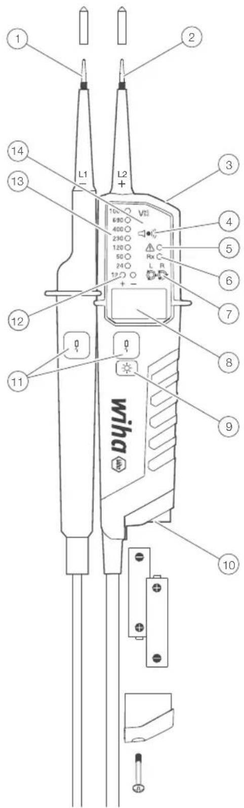
Tester information and control elements
① Test tip, L1
② Test tip, L2
③ Torch light
4 Buzzer hole for acoustic indication
⑤ Single pole test ELV warning
6 Continuity test
7 Rotary field
⑧ LCD display indication voltage, polarity and low battery
⑨ Torch light button / Activation R-measurement and low voltage measurement
10 Battery door
11 Trip TEST RCD pushbuttons
12 LED's indicating 12 V and polarity
13 Voltage indication
14 Display
Accessory
• 4 mm test tip adapters
- Plug on cover (GS38)
- Protective cover
Preparation for tests
Auto Power On / Switching On
- The tester switches on when it detects continuity, an AC or DC voltage above approx. 6 V or a live phase on L2 (single pole test).
- It can be switched on with the torch light button.
Auto Power Off
- Tester is automatically powered off after 30 sec when there is no signal contacted to the probes.
- The torch light switches off after approx. 30 sec.
Self-test
- When voltage tester is off short both probes L1 and L2, hold probes shorted.
- All LEDs, all symbols on LCD, buzzer and vibration will be on for 2 s.
- Self-test will start automatically when replacing batteries.

If some of LEDs is not ON, or some LCD symbols are not ON or buzzer or torch light is not ON, the device is not safe for use. Replace the battery and start Selftest again. If some of these indications are not ON again, the device is not safe for use and must NOT be used.

Do not use tester while Self-test procedure is activated.
Conducting tests
Voltage test
- Connect both probes to the object under test.
- The voltage is indicated by LEDs and LCD.
- Buzzer sounds and vibration is on when a threshold voltage of 50 V AC or approx. 120 V DC is exceeded.
• Voltage polarity is indicated in following manner.

AC: + and - 12 V LED are on

+DC: +12 V LED is on

-DC: -12 V LED is on (and “-” is shown on LCD)

When the L2 probe + is the positive (negative) potential, the polarity indication LED indicates “+DC” (“-DC”).

During voltage test, L or R LED may light up.

In case of empty batteries, the ELV LED lights up > 50 V AC/DC, > 120 V AC/DC.
Low voltage mode - 0.5 V - 1,000 V AC / 1,500 V DC
- Press torch button repeated until LCD shows < 10 V symbol.
- In low voltage mode it is possible to measure AC and DC voltage from 0.5 V.
- Connect both probes to the object under test.
Continuity mode is disabled in low voltage mode.
Single-pole phase test

Function of this test may not be fully achieved if the insulation condition/ grounding conditions of user or of the equipment under test aren't good enough. Verification of live-circuit shouldn't be dependent on this Single-pole phase test only, but on the voltage test.
- Hold the tester well in your hand. Connect the "L2+" probe to the object under test. Single pole LED lights up and buzzer sounds when a voltage of approx. 100 V AC or more exists in the object under test. (Pol ≥ 100 V AC).
Phase rotation test
- L LED and R LED for phase rotation test may operate on various wiring systems, but effective testing result can be obtained only on three-phase 4-wire system.
- Hold the tester good in your hand and connect both probes to the object under the test.
- Phase-to-phase voltage is indicated by voltage LEDs.
• R LED lights up for right rotary field.
• L LED lights up for left rotary field. - Measurement principle: The instrument detects the phase rising order regarding the user as earth.

Function of this test may not be fully achieved if the insulation condition/grounding conditions of user or of the equipment under test is not good enough.
Trip test of RCD

For voltage tests in systems with RCD (earth leakage circuit breakers) an RCD can be tripped with a 10 mA or 30 mA nominal leakage current on single phase AC 230 V power system.
- Connect probes "L1" and "L2" between L and PE of RCD protected system.
- Press simultaneously both of Trip TEST RCD pushbuttons.
• The RCD should trip.
Continuity test (Rx)

The test circuit/object shall be de-energized before measurement.
- Check for the absence of voltage by conducting a two pole voltage test on the test object.
- Connect both test probes together or press the torch light pushbutton to switch ON the tester.
- Connect both test probes to the test object. For continuity (up to approx. 500 kΩ) the continuity test LED – Rx is on and the buzzer is active.
- Continuity test automatically switches OFF after approx. 30 seconds if no continuity is detected. When tester is OFF, If continuity is detected it will be automatically switched on again.
Diode test

Make sure the object under test isn't live.
- Switch into diode testing mode by short pressing torch-button repeated until symbol is shown on LCD. Connect both test probes to the diode under test.
- Continuity LED lights up, buzzer sounds continuously and forward voltage is shown on LCD if L1 tip is connected on Anode of diode and L2 tip on Cathode.
- Continuity indication will be off if L1 tip is connected on Cathode of diode and L2 tip on Anode.
- Tester switch to voltage measurement if voltage > 6 V or single pole is detected during diode testing.
Resistance test

Make sure that object test isn't live.
- Switch into resistance measurement by short press of torch light. Connect both test probes to the object under test. Resistance up to 2 k show on LCD display. For resistance less than 30 Ohm buzzer sounds continuously to indicate low continuity.
• Second short press switches into voltage measurement.
Torch light
- Pressing the torch light button will turn on the light and after approx. 30 s it will turn itself off.
- When torch light is on, pressing the torch light button for more than 6 s will turn off the torch.
Data Hold
Under data hold mode, The LCD screen will only show the last saved measured voltage value. No auto refresh of LCD screen reading under Data Hold mode whether the voltage tester is connected to energized or non-energized circuit. The LED voltage indicators will always show the actual voltage of the circuit under measurement.
- After pressing the torch light push button for more than 2 seconds, the data hold function is activated and replies with a short sound. The LCD screen shows “the last measured value” and symbol “HOLD”. The hold function can be deactivated manually by pressing the torch light push button again. Function deactivation will be announced with a short sound.
Frequency test

Switch into frequency measurement by short pressing torch-button repeated until Hz symbol is shown on LCD. Connect both test probes to the AC voltage under test. Frequency from 16 Hz to 950 Hz can be shown on LCD.
Frequency measurement is possible for voltages > 10 V AC.
The level of voltage will be shown only on bar graph for voltages > 120 V. ELV diode will indicate voltages > 50 V AC and > 120 V DC.
Cable break detection by NCV

Switch into NCV mode by pressing torch button repeated. LCD will show NCV symbol.
- The NCV function is used to find e.g. after a cable breaks.
- Hold the voltage tester with the sensor against the wire or cable. The voltage tester indicates the strength of the signal digitally on the LCD screen.
- Store test probes safely to avoid any unintended connection.
- Tester switch to voltage measurement if voltage > 6 V or single pole is detected between probes.
Battery replacement

Remove the probes from any testing point, when opening the battery case. Batteries are empty when the continuity test with both test probes connected cannot be done anymore. A battery symbol in the LCD indicates low battery.
Follow the procedure below and replace batteries with new ones (type IEC LR03 1.5 V).
- Unscrew the battery door using Philips type screwdriver.
- Pull out the battery door and replace the batteries. Insert new batteries according to the engraving on the battery door.
• Re-assemble battery door.

Confirm that the battery door case is properly locked prior to measurements.
Technical data
Voltage range 0.5 V...1,000 V AC True RMS (16 2/3...950 Hz), 0.5 V...1,500 V DC(±)
LED nominal voltage 12/24/50/120/230/400/690/1,000 V, AC (16 2/3...950 Hz), DC(±)
LED tolerances according to EN 61243-3
ELV indication LED > 50 V AC, > 120 V DC
Response time < 0.5 s (LED); < 1 s (LCD)
LCD range 0.5 V...1,000 V AC, 1,500 V DC
LCD resolution 0.1 V(< 10 V) and 1 V (> 10 V)
LCD accuracy 3 % + 3 digit > 10 V, 3 % + 5 digit < 10 V
Crest factor 1 ... 10V: CF > 2.5 / >10 ... 300 V: CF = 5 / >300V...500V: CF = 3 / >500V...750V: CF = 2 / >750V CF = 1.5
LCD overrange indication "OL"
Peak current is < 3.5 mA (at 1,000 V)
Measurement duty 30 s ON (operation time), 240 s OFF (revocery time)
Internal battery consumption approx. 80 mA
Single-pole phase test voltage range 100...1,000 V AC (40...70 Hz)
Phase rotation test 170...1,000 V phase-to-phase, AC 40...70 Hz
Continuity test detection range 0...500 kΩ + 50 %
NCV test 100...1,000 V AC against earth (50/60 Hz)
Resistance measurement detection range 0...1,999 Ω ± (5 % + 10 dgt); resolution: 1 Ω
Frequency measurement 1...950 Hz +/- (5 % + 5-digit); resolution: 1 Hz; 10...1,000 V AC
Battery 3 V (IEC LR03 1.5 V x 2)
Diode test 0...2 V (+/- 5 % 10-digit); resolution: 0.01 V
Temperature -15...50 °C operation; -20...60 °C storage, No condensation
Humidity max. 85 % RH
Altitude up to 2,000 m
Overvoltage CAT. III 1,000 V / CAT. IV 600 V
Standard EN 61243-3:2014
Pollution degree 2
Protection IP64
Cleaning and storage

Tester does not need any special maintenance if used according to user manual.

Remove tester from all test points before cleaning.

Use a lightly damp cloth with neutral detergent for cleaning the instrument. Do not use abrasives or solvents. After cleaning, do not use device until completely dry.

Do not expose the instrument to direct sun light, high temperature and humidity or dewfall.

Remove batteries when the instrument will not be in use for a long period to prevent danger or damage due to possible battery leakage.
Safety advices
- Depending on the internal impedance of the voltage detector there will be a different capability of indicating the presence or absence of operating voltage in case of the presence of interference voltage.
- A voltage detector of relatively low internal impedance, compared to the reference value of 100 kΩ, will not indicate all interference voltages having an original voltage value above the ELV level. When in contact with the parts to be tested, the voltage detector may discharge temporarily the interference voltage to a level below the ELV, but it will be back to the original value when the voltage detector is removed.
- When the indication "voltage present" does not appear, it is highly recommended installing earthing equipment before work.
- A voltage detector of relatively high internal impedance, compared to the reference value of 100 kΩ, may not permit to clearly indicate the absence of operating voltage in case of presence of interference voltage.
- When the indication "voltage present" appears on a part that is expected to be disconnected of the installation, it is highly recommended confirming by another means (e.g. use of an adequate voltage detector, visual check of the disconnecting point of the electric circuit, etc.) that there is no operating voltage on the part to be tested and to conclude that the voltage indicated by the voltage detector is an interference voltage.
- A voltage detector declaring two values of internal impedance has passed a performance test of managing interference voltages and is (within technical limits) able to distinguish operating voltage from interference voltage and has a means to directly or indirectly indicate which type of voltage is present.
Service and warranty
Should the device no longer work, should you have any questions or require information, contact an authorised customer service point for Wiha power tools:
Customer care
Wiha Werkzeuge GmbH
Obertalstraße 3 – 7
78136 Schonach
GERMANY
Tel.: +49 7722 959-0
Fax: +49 7722 959-160
Email: info.de@wiha.com
Website: www.wiha.com
The warranty is voided in the event of injury or damage to property caused due to non-compliance with these instructions. The manufacturer accepts no liability for consequential damage!
Contenu
Introduction 4
Zone LCD 0.5V...1000V CA, 1500V CC
Website: www.wiha.com
Egnet for arbeid under spenning.