DSX Touch - Boiler Clage - Free user manual and instructions
Find the device manual for free DSX Touch Clage in PDF.
User questions about DSX Touch Clage
0 question about this device. Answer the ones you know or ask your own.
Ask a new question about this device
Download the instructions for your Boiler in PDF format for free! Find your manual DSX Touch - Clage and take your electronic device back in hand. On this page are published all the documents necessary for the use of your device. DSX Touch by Clage.
USER MANUAL DSX Touch Clage
text_image
Clancy 38 + - CLAGE and/or to be lost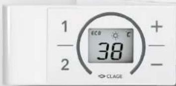
text_image
1 - 2 ECO 38 + - CLAGEInhaltsverzeichnis
Gebrauchsanleitung
natural_image
White cylindrical water heater with digital display showing 38°C and control buttons (no text or symbols on main body)CE
text_image
Mobile app interface with icons for user profile, speed slider, and cleaning tool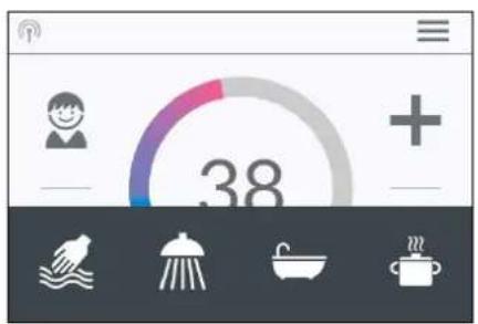
text_image
38Statusanzeige oben
natural_image
Simple black-and-white line drawing of a cloud with two horizontal lines below (no text or symbols)Energiespartipp
text_image
Diagram showing three steps of installing a digital display panel with numbered annotationstext_image
Technical diagram showing a digital display panel connected to a wall-mounted panel with dimension annotations and numbered parts.text_image
Warning symbol with exclamation mark inside trianglenatural_image
3D CAD model of a mechanical housing frame with internal grid structure and mounting holes (no text or symbols)Montagezubehör
natural_image
Product diagram of VDX connectors and terminal parts (no text or symbols)Rohrbausatz VDX
natural_image
Product assembly of flexible hose connectors and connector parts (no text or symbols visible)Rohrbausatz UDX
natural_image
Technical line drawing of a mechanical bracket assembly (no text or symbols)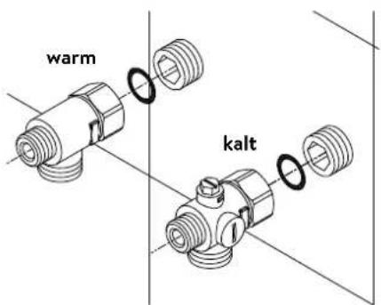
text_image
warm kaltnatural_image
Technical line drawing of an electronic device interior with circuitry and components (no text or symbols)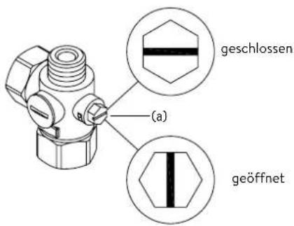
natural_image
Technical line drawing of a mechanical bracket assembly with mounting holes and internal fasteners (no text or symbols)
text_image
co30°
text_image
co 30°text_image
Diagram showing three steps of installing a wall-mounted panel, with numbered annotations indicating component placement.Abbildung B:
text_image
Technical diagram showing a digital display panel connected to a wall-mounted panel with dimension annotationsnatural_image
Technical line drawing of a mechanical assembly with exploded and assembled views (no text or symbols)text_image
Technical diagram showing a mechanical component with an inset close-up of a textured surface, illustrating assembly or assembly process.7. Elektroanschluss
Schaltplan
text_image
2 4 6 8 1 A C 5 L3 L2 L1 PE 3 P 4 3/PE~ 1 2 3 4text_image
180mm 60mm 8mmnatural_image
Cross-sectional diagram of an electrical enclosure with visible wiring, switches, and warning symbol (no text labels)Multiple Power System MPS®:
text_image
Technical diagram showing a disassembled electronic device with labeled parts and a tool inserted into it.text_image
Technical diagram showing internal components of a device with numbered parts and an arrow indicating assembly or connection.Pos. AUS Pos. 1
Sperrfunktion
text_image
Technical diagram showing a mechanical component with a close-up view of a textured surface inside a housing.Operation instruction
- Description of the appliance .... 33
Simplified EU Declaration of Conformity 33
- How to use 34
Main control 34
Main menu....35
Statistics 36
Settings 36
User 39
Savings....39
Info....39
Power limit 39
Top-up heating 39
How to save energy....39
Venting after maintenance work....40
Cleaning and maintenance....40
- Remote control 41
Mounting the wall bracket....41
Initial operation....41
Registration of remote control at the instant water heater.41
Handling 42
Displayed information....43
Safety notes....43
Battery replacement....43
Disposal 43
- CLAGE app "Smart Control" 44
Initial operation....44
Connecting via Bluetooth....44
Connecting via WLAN....44
Activate/ deactivate Wi-Fi 45
Software update....45
Use 45
-
Trouble-shooting and service....46
-
Product data sheet in accordance with EU regulation - 812/2013 814/2013 .... 47
Installation instruction
-
Overview....48
-
Technical specifications ....49
-
Environment and recycling 49
-
Dimensions....50
-
Installation....50
Installation site....50
Mounting accessories 51
Installing the wall bracket....52
Installing connection pieces....52
Installing the appliance 53
Mounting the remote control's wall bracket....54
-
Direct connection .... 55
-
Electrical connection....56
Wiring diagram....56
Structural prerequisites .... 56
Load shedding relay....56
Electrical connection from below....57
Electrical connection from above....57
- Initial operation....58
Selection of power rating....58
Reinstallation....58
Notes in case of remote control connection problems....59
Shower application 59
Locking function 59
- Maintenance work....60
Cleaning and replacing the filter strainer ....60
Cleaning and replacing the filter strainer if direct connected....60
The documents supplied with the device must be stored carefully.
Registration
Register your device online on our website and benefit from our services under warranty.
Your full details help our customer service process your request as fast as possible.
For online registration, just follow the link below or use the QR code with your smartphone or tablet.
https://partner.clage.com/en/service/device-registration/
Operation instruction
Note: Carefully read the enclosed safety instructions through in full before the appliance is installed, put into service and used and follow them in the further steps and during use!
1. Description of the appliance
natural_image
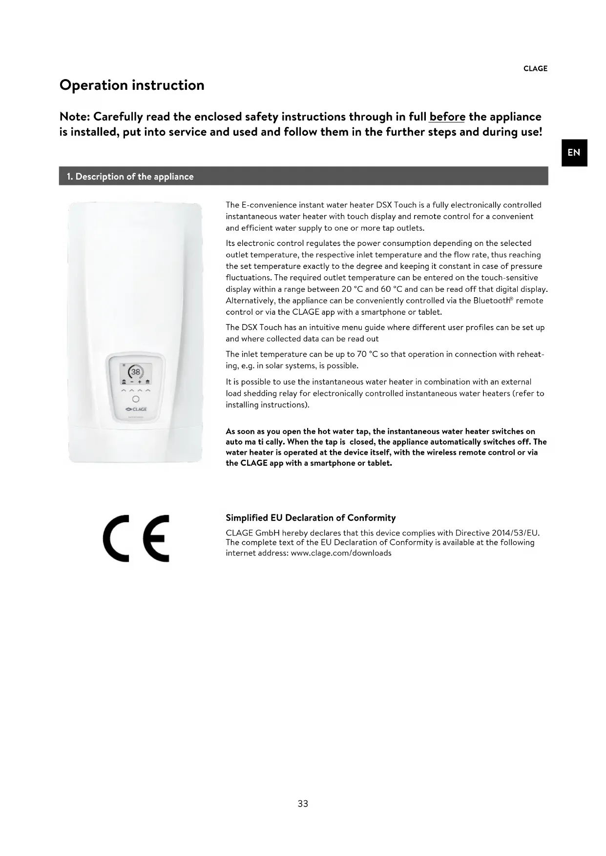
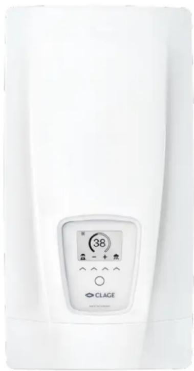
White industrial water heater with digital display showing 38°C and control buttons (no text or symbols on main body)The E-convenience instant water heater DSX Touch is a fully electronically controlled instantaneous water heater with touch display and remote control for a convenient and efficient water supply to one or more tap outlets.
Its electronic control regulates the power consumption depending on the selected outlet temperature, the respective inlet temperature and the flow rate, thus reaching the set temperature exactly to the degree and keeping it constant in case of pressure fluctuations. The required outlet temperature can be entered on the touch-sensitive display within a range between 20 °C and 60 °C and can be read off that digital display. Alternatively, the appliance can be conveniently controlled via the Bluetooth® remote control or via the CLAGE app with a smartphone or tablet.
The DSX Touch has an intuitive menu guide where different user profiles can be set up and where collected data can be read out
The inlet temperature can be up to 70 °C so that operation in connection with reheating, e.g. in solar systems, is possible.
It is possible to use the instantaneous water heater in combination with an external load shedding relay for electronically controlled instantaneous water heaters (refer to installing instructions).
As soon as you open the hot water tap, the instantaneous water heater switches on auto ma ti cally. When the tap is closed, the appliance automatically switches off. The water heater is operated at the device itself, with the wireless remote control or via the CLAGE app with a smartphone or tablet.
CE
Simplified EU Declaration of Conformity
CLAGE GmbH hereby declares that this device complies with Directive 2014/53/EU. The complete text of the EU Declaration of Conformity is available at the following internet address: www.clage.com/downloads
2. How to use
Main control
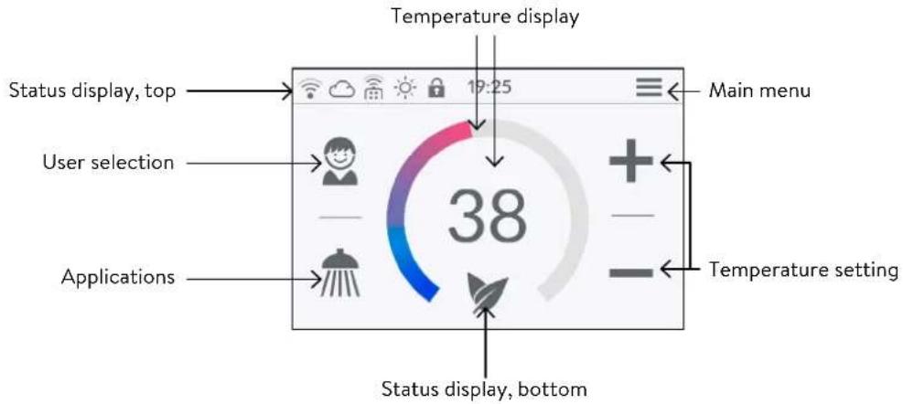
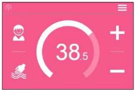
The display shows the main control by default. The current status is displayed and by tapping on the touch screen you get access to various submenus and functions.
text_image
Temperature display Status display, top 19:25 Main menu User selection 38 Applications Temperature setting Status display, bottomTemperature display
The coloured scale ring fills up as the temperature setting is increased and the colour changes from blue when the temperature is low to red when the temperature is high. In addition, the target temperature is displayed in ^ C as a figure in the middle of the display.
Temperature setting
The desired temperature can be selected by tapping on + and - for the fine setting or by dragging along the coloured scale ring for a quick selection within a range of 20°C to 60°C. Tapping + or - once changes the temperature by 1°C, in the comfort range between 35 and 43°C by 0.5°C. If the temperature is set below 20°C, the symbol -- appears in the temperature display and the appliance switches off the heating function.
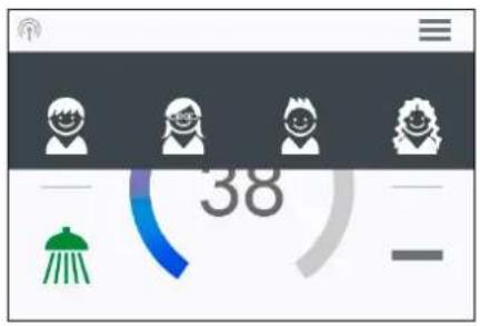
User selection
Up to eight user profiles can be created. Every user has the option to save his desired temperatures for the different uses in a profile. The user profiles can be selected by tapping on the profile image and the temperatures saved in the profile are set (to create profile, see Section "User").
Applications
Preset applications can be selected here. Simply tap on the desired symbol. The temperatures set at the factory (handwash = 35°C, shower = 38°C, bath = 40°C, hot water = 48°C) can be changed for each application via the temperature setting. If you touch the temperature value in the temperature display or the application symbol for 3 seconds, the temperature is saved for the selected application. The temperature display flashes once for confirmation. Application temperatures saved in the user profile can be called up at any time by tapping on the corresponding symbol.
text_image
38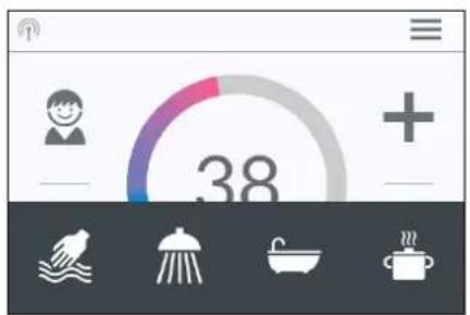
text_image
38Status display, top
Control lock active (PIN)
The inlet temperature exceeds the target value (appliance does not heat up)
Bluetooth remote control registered
Wi-fi is activated
The appliance is connected to the CLAGE Cloud
Status display, bottom
Display area for functions which require confirmation from the user or which are of great significance.
2. How to use
text_image
38.5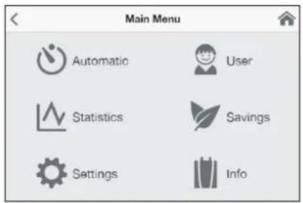
text_image
Main Menu Automatic User Statistics Savings Settings Info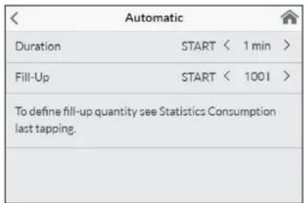
text_image
Automatic Duration START < 1 min > Fill-Up START < 1001 > To define fill-up quantity see Statistics Consumption last tapping.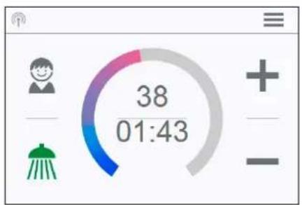
text_image
38 01:43
text_image
42 90,0 LEco active: The outlet temperature for all applications and the water flow are limited to an energy-efficient value. If the temperature is set higher via the temperature setting, the symbol starts to flash.
√ Maintenance: Tap the symbol to open a status message with additional information.
MAX Maximum temperature reached: The temperature cannot be increased any further since the set temperature limit has been reached. The temperature limit can be changed in the main menu under "Settings".
Drawing mode
If heated water is drawn from a tap, the main control changes to drawing mode and, depending on the set outlet temperature, changes the background colour from blue for low temperatures to red for high temperatures. In this mode the scale ring displays the actual power consumption of the appliance.
Main menu
All function menus and saved values of the appliance can be selected from here. Tap on the 🔗 symbol to go back to the main control.
Automatic
In this menu, two functions can be selected. Automatic either measures the time in seconds via the function "Duration" or the flow of heated water in litres via the function "Fill-Up". Cold water added at the tap cannot be recorded by the appliance. In order to use the Automatic function correctly according to the fill quantity, it is therefore necessary to set the desired temperature on the appliance and only turn on the hot water tap.
For each function per user profile, the last set start value is saved and can be activated at any time.
Note: In Automatic mode, the operating functions are limited. When selecting a limited function, an instruction window appears. Tap on "OK" to deactivate Automatic mode and all functions are freely available again. Tap on "Cancel" to close the instruction window and Automatic mode remains active.
Duration: Under "Duration", tap on
Tap on the time or turn on the hot water tap to start the function and the time starts to count down as seconds. Tap on the time again to pause and restart the function at any time. Turning off the tap does not pause the function. If hot water is already flowing whilst the function is activated, it starts immediately. To cancel the function, touch the time for three seconds.
When the time has elapsed, "00:00" flashes briefly. In addition, the flow quantity, if it is being drawn, is reduced for around 10 seconds and then increased again. A short acoustic signal is heard.
Fill-Up: Under "Fill-Up" tap on or to set the desired water quantity and then tap on "START" to activate Automatic mode. The view changes to the main control where the set quantity is displayed directly below the temperature display. Turning on the hot water tap starts the function and the set fill quantity counts down in litre increments according to the flow measurement.
Continued turning off and on of the tap pauses and restarts the function. If hot water is already flowing whilst the function is activated, it starts immediately. To cancel the function, touch the fill quantity for three seconds or turn off the water flow for a minute.
2. How to use

When the fill quantity is reached, "O I" flashes briefly on the display and the appliance stops the water flow by closing the motor valve. A long acoustic signal can also be heard and an instruction message appears on the display. The motor valve stay closed until the message is confirmed at the appliance or via app.
Turning off the tap is always necessary, the function must therefore not be used unsupervised.
Before using the bath, make sure that the water temperature is what you want it to be.
Hint: The water amount of the last draw-off is stored in the "Statistics" menu. To determine the necessary amount of water for your bathtub, fill it with warm water, then select "Statistics" in the main menu and read out the value of this last drawing. Enter this value in the automatic function "Fill-Up" to use it for the next bathtub filling.
Note: In the event of a power cut whilst the automatic is running according to the fill quantity, the water flow is stopped by the motor valve. After power is restored the valve remains closed a prompt appears on the display and an alarm signal can be heard until the prompt is acknowledged by tapping on "OK".
text_image
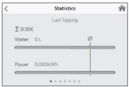
Statistics Last Tapping Σ 0.00€ Water 0 L Power 0.000kWhStatistics
The statistics save the consumption and usage data for the appliance and display them in graph format:
Water consumption
Power consumption
Σ Total consumption costs
Wipe from right to the left to scroll the different periods. The consumptions are displayed consecutively in diagrams over a period from the last drawing of water, the consumption today, the consumption yesterday, over the last seven days, the last four weeks, the last twelve months and the last four years.
Note: The consumption data are not suitable for billing purposes.
Settings
This menu is used for the basic configuration on the appliance. Wipe to scroll through the different menu items and tap on the values to change settings directly or go to different submenus.
text_image
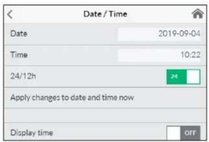
Date / Time Date 2019-09-04 Time 10:22 24/12h 24 Apply changes to date and time now Display time OFFDate / Time: The DSX Touch automatically receives its system time as soon as the device is connected to a network with Internet access. Alternatively, you can set the time manually and save it by tapping on "Apply changes to date and time now".
Note: Without an Internet connection, the time will be lost in the event of a power failure.
Language: Select the menu language.
Currency: Select a currency symbol.
Temperature Unit: Defined as °C.
text_image
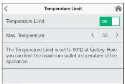
Temperature Limit Temperature Limit ON Max. Temperature < 53 > The Temperature Limit is set to 60°C at factory. Here you can limit the maximum outlet temperature of the appliance.Temperature Limit: The temperature limit can be activated / deactivated in this menu and the maximum outlet temperature can be limited to a desired value within the temperature setting range by tapping on
Note: If the instantaneous water heater supplies a shower, then the maximum temperature was limited to 55 °C during the installation of the appliance and the function was disabled.
2. How to use
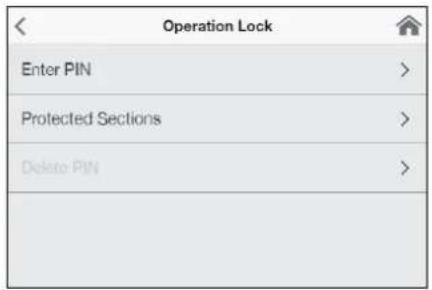
Operation Lock: Secure your settings with a four-digit PIN.
Note: The operation lock can only be deactivated with the correct PIN under "Protected Sections" or under "Delete PIN". If you should forget your PIN, please contact after-sales Services.
Enter PIN: Numbers from 0 to 9 can be selected via the keypad. If you have selected four digits, confirm by tapping on "OK". The PIN must then be entered again and confirmed for security reasons.
If both entries match, you access the section "Protected Sections".
text_image
Operation Lock Enter PIN > Protected Sections > Delete PIN >
text_image
Enter PIN 1 2 3 4 1 2 3 4 5 6 7 8 9 OK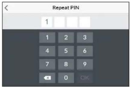
text_image
Repeat PIN 1 1 2 3 4 5 6 7 8 9 × 0 OK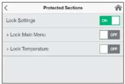
text_image
Protected Sections Lock Settings ON + Lock Main Menu OFF + Lock Temperature OFFProtected Sections: Select the areas for a PIN lock.
- Lock Settings: Automatically active as soon as a password has been generated. Users can only access the settings menu with a PIN. Deactivating it deletes the current PIN.
-
- Lock Main Menu: Users can only access the main menu with a PIN
-
- Lock Temperature: The outlet temperature is set to the current value and can only be changed with a PIN. User profiles, applications and Eco mode can also only be changed with a PIN.
text_image
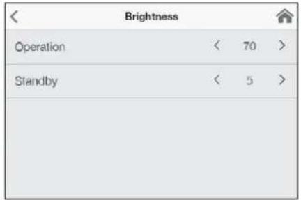
Brightness Operation < 70 > Standby < 5 >Brightness: Reduce the display brightness e.g. to safe energy. The brightness can be set separately for operation screen and standby mode.
• Operation 5-100%
- Standby 0-100% (0% = display OFF)
The setting of the standby mode will be activated after 1.5 minutes.
Sound: Activate / deactivate operating sounds.
Note: Alarm signals and instruction sounds can not be disabled.
| Value | Description |
| 0 | Operation without load shedding relay, factory setting |
| 1 | Operation with normal load shedding relay |
| 2 | Operation with sensitive load shedding relay |
Load Shedding (Expert Mode): If further three-phase appliances are connected, a load shedding relay designed for electronic instantaneous water heaters (CLAGE no. 82250) can be connected to phase conductor L2. This relay ensures the operation of the water heater by switching off other consumers until the end of heating operation.
Tap on
Operating mode 1 must be selected first, thus to check the correct operation of the load shedding relay at low appliance output (35 degree celsius setpoint and low water flow rate). Mode 2 must be selected if the load shedding relay flickers.
Thermal treatment: With this function, you can support a thermal treatment of your appliance and the following pipeline, including the tap. A thermal disinfection according to the accepted rules of technology is not replaced.
- Tap OK to start the treatment cycle and the outlet temperature is set to 70 °C. The function is disabled if the appliance is connected to a shower.
- Draw hot water for at least three minutes to heat the pipes to the tap completely.
- A change of the temperature or 30 sec without water flow terminates the treatment cycle.
- The number as well as the accumulated duration and the water amount of all thermal treatments will be saved.
2. How to use
Notes:
Ensure that no one can be injured by the elevated temperatures and that the installation can withstand the strain.
The exiting water and the tap become very hot! The water steam should not be inhaled.
| Settings | |
| Flow Limit | < AUTO > |
| Factory Settings | > |
| Initialize Statistics | > |
| Devices | > |
| Software Info | > |
Flow Limit: Setting of flow rate limitation.
Setting options:
"OFF" no flow rate limitation (motor valve deactivated)
"AUTO" automatic adjustment, i.e. flow rate is limited in a way so that the selected outlet temperature is reached
“ECO” flow rate limitation to max. 8.0 l/min
e.g. "9.0" limitation to a freely selectable value between 4.5 and 25 l/min
Note: If the Eco function has been activated in the menu "Savings", the flow is automatically set to "ECO". Changing the flow deactivates the Eco function
| Factory Settings | |
| Restart Device | |
| Factory Reset | |
| Reset User Settings | |
Factory Settings: All factory settings can be recalled:
- Restart Device: Set the temperature back to factory setting and restart the appliance.
- Factory Reset: Deletes all entries made by the user inclusive statistics.
- Reset User Settings: Deletes all user profiles.
Synchronize Statistics: Use this function to reload the statistical data.
Devices: All settings for operation with the app and for integrating the DSX-Touch into a Wi-Fi network are made here. For more information, see chapter: "4. CLAGE app Smart Control".
| Software Info | |
| Version | 1.4.2 |
| Imprint | > |
| Open Source Licenses | > |
| Expert Mode | OFF |
Software Info: Information about the operating system, the imprint and licenses can be viewed here. The "Expert Mode" can also be activated here. In the expert mode you have access to sensitive system settings and functions.
2. How to use
text_image
User Add User Andreas Maria
text_image
Savings Electr. Tariff (€/kWh) 0.28 Water Tariff (€/m³) 4.00 Eco Settings OFFUser
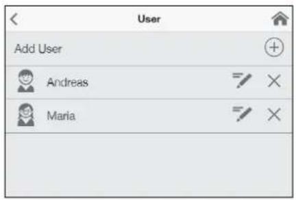
Up to eight users can enter their names and select their own profile image. This appears together with the first letters of the name in the main screen.
In the main control, every user can set up and save his own desired temperatures for the different applications.
Tap the + symbol to add more profiles, use the pen to edit existing profiles and tap the × symbol to delete the adjacent user profile.
Savings
Here, you can determine the parameters for the costs in the consumption statistics and activate / deactivate the ECO mode. You can select a currency symbol under "Settings".
Electricity Tariff (€/kWh): Indicate the electricity price from your electricity company.
Water Tariff (€/m ^3 ): Indicate the water price from your water company.
ECO Settings: In Eco mode the outlet temperatures are limited to an energy-efficient value (handwash = 35°C, shower = 38°C, bath = 40°C, hot water = 48°C).
Additionally the water flow is limited to 8 l/min.
text_image
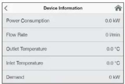
Device Information Power Consumption 0.0 kW Flow Rate 0 l/min Outlet Temperature 0.0 °C Inlet Temperature 0.0 °C Demand 0 kWInfo
The current status and appliance data is listed here. By wiping you can scroll through the different information values.
Power limit
If the full output of the instantaneous water heater DSX Touch does not suffice to heat the tapped quantity of water, the control valve automatically reduces the flow rate so that the set temperature is reached.
Top-up heating
When operating with preheated water (e.g. with solar systems), you must ensure that the inlet temperature does not exceed 70 °C.
If the inlet temperature exceeds the setpoint, the appliance is not providing any output. The symbol ✿ is displayed in the main screen

natural_image
Simple black-and-white line drawing of a tree with two horizontal lines below (no text or symbols)How to save energy
Set the exact temperature you need on the appliance and open the hot water tap. Once you feel that the water is too hot, do not add any cold water and, instead, enter a lower temperature on the appliance. If you were to add cold water, the water already heated would cool down again and valuable energy would be wasted. Moreover, the cold water added in the tap is not covered by the control range of the electronic circuitry, with the result that temperature constancy is no longer guaranteed.
2. How to use
EN

Venting after maintenance work
This instantaneous water heater features an automatic air bubble protection to prevent it from inadvertently running dry. Nevertheless, the appliance must be vented before using it for the first time. Each time the appliance is emptied (e.g. after work on the plumbing system, if there is a risk of frost or following repair work), the appliance must be re-vented before it is used again.
- Disconnect the instantaneous water heater from the mains (e.g. via deactivating the fuses).
- Unscrew the jet regulator on the outlet fitting and open the cold water tap valve to rinse out the water pipe and avoid contaminating the appliance or the jet regulator.
- Open and close the hot water tap until no more air emerges from the pipe and all air has been eliminated from the water heater.
- Only then should you re-connect the power supply again (e.g. via activating the fuses) to the instantaneous water heater and screw the jet regulator back in.
- The appliance activates the heater after approx. 10 seconds of continuous water flow.
Cleaning and maintenance
- Plastic surfaces and fittings should only be wiped with a damp cloth. Do not use abrasive or chlorine-based cleaning agents or solvents.
- For a good water supply, the outlet fittings (e.g. jet regulators and shower heads) should be unscrewed and cleaned at regular intervals. Every three years, the electrical and plumbing components should be inspected by an authorised professional in order to ensure proper functioning and operational safety at all times.
3. Remote control
text_image
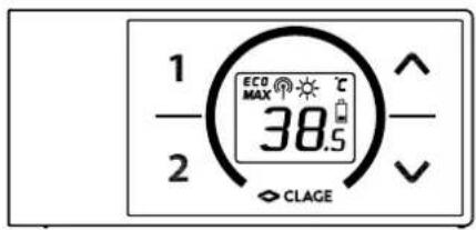
1 2 ECO MAX 38.5 CLAGETechnical data
| Model FX 3 Remote control | |
| Operating voltage 3V | |
| Type of battery 2x AAA Alkaline | 1) |
| Type of protection IP20 | |
| Transmission range 10 metres incl. barrier | |
| Transmission power < 8 mW | |
| Transmission and receiving frequency range | 2.4 – 2.4385 GHz |
| Radiation undirected | |
| Approvals | Europe EN 300 328 / CE |
1) Do not use rechargeable batteries.
Figure A: Installation with adhesive tape
text_image
Diagram showing three steps of a door panel installation with numbered components and directional arrows indicating movement.Figure B:
Optional installation with dowels and screws

text_image
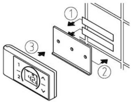
Technical diagram showing a digital display panel connected to a wall-mounted panel with dimension annotationsMounting the wall bracket
- Before attaching the wall bracket to the wall, ensure that the remote control has radio contact to the instantaneous water heater from its designated position and is protected against splashing water.
- The wall bracket of the remote control can either be attached securely with the included adhesive tape, after stripping off the protection film (as shown in the figure A), on a rigid board (e.g. tile) or with suitable dowels (∅ 4 mm) and screws (as shown in the figure B).
- When mounting with adhesive tape, ensure that the mounting surface is dry and free of grease and soap.
- When using the adhesive tape it is not possible to further adjust the position because of the strong adherence of the glue. Therefore, pay attention to a horizontal alignment when attaching it.
- The remote control is magnetically retained at the wall bracket.
- Keep the remote control and wall bracket away from credit cards or other cards with magnetic strips. The built in magnets can damage the card's magnetic strip.
Initial operation
By the time the power settings have been carried out and the power supply to the instantaneous water heater is enabled, insert the batteries into the remote control.
Registration of remote control at the instant water heater
- Make sure that the power supply to the instantaneous water heater is switched on (fuse).
- After inserting the batteries, the remote control briefly displays all symbols. Then "BR" and the percentage of battery charge are displayed and the display changes to the PIN entry "P i".
- Press — and to change the current digit. Press to change to the next digit. After entering "P4" and pressing ①, the PIN is applied.
- Enter the first four digits of the Bluetooth PIN and confirm with ①. The PIN can be found on or at the type plate of your instantaneous water heater.
- After entering the pin, the remote control automatically connects to the instantaneous water heater, "d l" appears during the registration procedure.
- Once connected, the display of the remote control switches to the setpoint value display.
In the case of an unsuccessful registration the display indicates “E i” and a flashing radio signal after 45 seconds. The remote control quits the registration process and switches to standby mode. By pressing a key the registration process will be repeated.
3. Remote control
Notes:
- With no remote control registered or without working radio connection, the instantaneous water heater heats to the prior selected set temperature.
- In case of persistent connection problems, restart the login by pressing and holding all four buttons on the remote control simultaneously for five seconds.
Handling
The remote control is equipped with the following functions:
1. Temperature buttons
You can set the required temperature gradually to a lower or higher value using the two buttons — and +
Note: If the temperature display is set to “--” with button —, the instantaneous water heater switches off the heating function.
2. Programme buttons
The two programme buttons ① and ② allow to quickly select the preset temperature without the need to press the + and - buttons several times.
The factory setting for programme ① is 35 °C and for programme ② it is 48 °C. You can assign your own settings for the programme buttons:
- Select the desired temperature with - and +
- To save the current temperature, press the programme button ① or ② for min. two seconds.
3. Restart and battery capacity
Press and hold the keys — and for approx. 2 seconds to restart the remote control. All symbols are displayed briefly, followed by the battery display "8A".
4. Info menu
Press and hold the programme keys ① and ② for about 5 seconds to open the info menu. Press ③ or briefly to navigate back and forth in the displays. Long presses on ① and ② exit the menu again.
Menu displays:
In Info menu indicator
BR Current battery capacity in percentage
Er Current error status
E, Temperature of water inlet in °C
to Temperature of water outlet in °C
EL Highest selectable temperature in °C
FL Current water flow in l/min
P_0 Current power consumption in kW
PP Current power consumption in percentage
PL Maximum appliance power in kW
CR Calibration value
r5 Signal strength in percentage
n ! Software version digit 1
n2 Software version digit 2
n3 Software version digit 3
P1 Digits 1 and 2 of the stored pin
P3 Digits 3 and 4 of the stored pin
3. Remote control
Displayed information
Energy saving mode ECO
The symbol E68s that the appliance works in an energy saving mode, i.e. the momentary energy consumption is subject to the selected temperature and to the flow rate in the energy saving mode.
Power limit MAX
If the full output of the instantaneous water heater does not suffice to heat the tapped quantity of water, this will be indicated by MAXthe FX 3-display.
Operation with preheated water
If the cold water inlet temperature is higher than the set value of the hot water outlet, the instantaneous water heater will not heat. In this case no power is emitted and the sun symbol 🌐 is displayed.
Safety notes
- At malfunction of the remote control remove the batteries immediately.
- Do not expose the remote control to moisture.
- Flat batteries can leak and damage the remote control. Hence, replace flat batteries right away as soon as battery symbol lights up in the display or the remote control does not response after keystroke.
- When the remote control is not to be used in the long term, remove the batteries.
- Without working radio connection, the appliance heats to the prior selected set value.
Battery replacement
Replace the batteries with new AAA-batteries when the battery symbol flashes up.
- Do not use rechargeable batteries!
• Non-rechargeable batteries are not to be recharged. - Different types of batteries or new and used batteries are not to be mixed.
- When replacing the batteries, observe the correct polarity.

Disposal
Batteries may contain environmentally hazardous substances. Therefore, used batteries must be disposed of at special collecting points and not be mixed with general household waste.
At the end of the remote control's lifetime, the batteries must be disposed of separate from the appliance.
4. CLAGE app "Smart Control"
A
| Devices | |
| Searching Home Servers... | |
| Setup Home Server manually | > |
| Bluetooth Interface | > |
| Setup Assistant | > |
| Demo Mode | OFF |
B
| Devices | |
| No devices found. | |
| Setup Home Server manually | > |
| Bluetooth Interface | > |
| DFX_4521201101052108/16/2021 12:10:18 | + |
| DSX_06212049FFEE2208/16/2021 12:10:18 | + |
| Setup Assistant | > |
| Demo Mode | OFF |
| < | Connect Device |
| In order to connect to your device, please scan the QR Code on the device or enter the Bluetooth PIN manually. | |
| Scan QR Code | > |
| Enter PIN | > |
| Advanced | |
| WLAN | ON |
| Operation Mode | Client > |
| The Home Server is connected to your existing WIFI-Network. | |
| Network | CLAGE_DE > |
| Password | |
Initial operation
The Smart Control app can be connected to the DSX Touch either via Bluetooth or via WLAN.
- Make sure that the instantaneous water heater is supplied with voltage.
- Install the control app on your tablet / smartphone. Search the Apple AppStore or the Google Playstore for »CLAGE Smart Control« and install the app. Do not start the control app yet.
Connecting via Bluetooth
- Activate the Bluetooth function of your smartphone / tablet.
- Start the Smart Control Control app and confirm all security prompts.
Note: No location-related data is processed. Activating and accepting the location function is required due to new guidelines for all Android apps with Bluetooth function.
- A message appears the first time the app is activated. Tapping on "OK" takes you to the device configuration "A" for manual setup (menu path: Main menu → Settings → Devices). Tapping on "Demo" allows you to explore the app control. You can exit demo mode again under (Main menu → Settings → Devices).
- Select "Bluetooth Interface" and tap on "Search devices...".
- A maximum of ten Bluetooth devices found are then scanned and listed "B". If your device is not included, repeat the scan.
- Select your device and confirm with "OK".
- Enter the Bluetooth PIN manually or scan the QR code. Both can be found on the type plate under the panel at the bottom of the unit.
- The unit is now connected to your smartphone / tablet. Check the function by changing the temperature via your smartphone / tablet. The display of the device must show the same value.
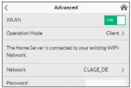
Connecting via WLAN
Configuration as Client
Control via smart speakers, e.g. with Amazon Alexa, is only possible if the DSX Touch has been registered as a client on a network with Internet access.
- Protect the appliance from unauthorised access by connecting it to an Internet-connected IT infrastructure only if it is protected by a firewall.
-
Protect the appliance against unauthorised access by using a secure Wi-Fi password. This should consist of letters, numbers and special characters and should not be listed in the lexicon.
-
Go to the device configuration (menu path: Main menu → Settings → Devices), select your DSX server and tap on "Advanced".
-
All networks found in range are listed at "Network". Tap your SSID to select your home network. If the SSID of your home network is hidden, it must be temporarily set to "visible" for the configuration.
-
Enter your Wi-Fi password and tab on "Apply"
-
The DSX Touch updates the Wi-Fi settings and tries to log in on the router using the new access data. The tablet / smartphone must be connected to the same network.
-
Start the Smart Control app and confirm the initial setup prompt with "OK".
-
You will get to the device configuration and can check the successful installation by selecting the DSX server and tapping on "Connect...". The following text should be displayed: "The Home Server can be used".
Note: A time delay of a few seconds is normal and dependent on the network infrastructure and utilization.
4. CLAGE app "Smart Control"
Configuration as Access Point
If you want to use the DSX Touch as a stand-alone access point, please set up an individual and secure password to protect it from unauthorised access:
- Go to the device configuration (menu path: Main menu → Settings → Devices), select your DSX server and tap on "Advanced".
- Select "Operating mode" and switch to the operating mode "Access Point".
- Enter an individual SSID under SSID and a secure password under Password. The password should contain numbers and letters and must be at least 8 digits long.
- Connect the tablet / smartphone to the DSX Touch by entering the access data you have just selected in the WLAN settings of your tablet / smartphone.
- Start the Smart Control app and confirm the initial setup prompt with "OK".
- You will get to the device configuration and can check the successful installation by selecting the DSX server and tapping on "Connect...". The following text should be displayed: "The Home Server can be used".
Note: If you have forgotten your password, select a new password directly at the device.
text_image
Advanced WLAN ON Operation Mode Client > The Home Server is connected to your existing WIFI- Network. Network CLAGE_DE > PasswordActivate/ deactivate Wi-Fi
Go to the device configuration, select the DSX server and tap »Advanced«. By tapping on the button, you can enable / disable the WLAN.
Software update
Updating the Smart Control app
We recommend using the latest software in order to ensure the impeccable and secure operation of the DSX Touch.
Any new control app version will be indicated in the app store.
- Updating iOS-devices: For updating your control app, select the "Updates" tab in the appstore and tap on the "Update" button which is to the right of the control app.
- Updating Android-OS-devices: For updating your control app, select the Smart Control app in the Google Playstore and tap on the "Update" button.
Updating the DSX Touch firmware
Note: Do not disconnect your DSX Touch from power supply during updates.
For an update the DSX Touch must be connected to a Wi-Fi network with internet access.
The instantaneous water heaters is unavailable during the update for several minutes.
-
Go to the device configuration in the settings menu: (Main menu - Settings - Device).
-
Select the DSX Touch which you want to update.
-
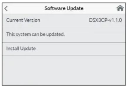
Select "Software", then "Install update" and confirm the following message.
-
Wait for about 10 minutes until the control panel restarts and check the function of the DSX Touch.
If an update is not possible even after multiple attempts, contact the after-sales service.
Use
All functions described in chapter "3. How to use" can also be controlled via the Smart Control app.
text_image
Software Update Current Version DSX3CP-v1.1.0 This system can be updated. Install Update5. Trouble-shooting and service


text_image
Warning symbol with exclamation mark inside triangleRepairs must only be carried out by authorised professionals.
If a fault in your appliance cannot be rectified with the aid of this table, please contact the service organisation of your importer or the Central Customer Service Department. Please have the details of the typeplate at hand.
CLAGE GmbH
After-Sales Service
Pirolweg 4
21337 Lüneburg
Germany
Phone: +49 4131 8901-400
Email: service@clage.de
This instantaneous water heater was manufactured conscientiously and checked several times before delivery. Should malfunctions nevertheless occur, it is usually only due to a bagatelle. First attempt to switch the house fuses off and on again in order to reset the electronics. Next, try to remedy the problem with reference to the following table. In doing so, you will avoid unnecessary expense of customer service assistance.
| DSX Touch | ||
| Problem Cause Solution | ||
| Water stays cold, touch display does not light up | Master fuse tripped Renew | or activate fuse |
| Safety pressure cut-out tripped | Contact customer service | |
| Display shows error symbol | The appliance has detected an error. | Switch fuses off and on. If symbol “wrench” is still indicated, contact customer service |
| Flow rate of hot water too weak | Outlet fitting dirty or calcified | Clean shower head, jet regulator or sieves |
| Fine filter dirty or calcified | Let clean fine filter by customer service | |
| Water flow is limited | Deactivate Eco mode and flow limit | |
| Selected temperature is not reached | Water flow rate too high | (Re)activate motor-driven valve in the menu “Flow Limit” |
| Cold water has been added via the tap | Tap hot water only; set temperature, check outlet temperature | |
| Touch display does not respond correctly or only sporadically | Display glass is wet | Dry display by wiping it with a soft cloth |
| App can't find the DSX Touch | Master fuse tripped Renew | or activate fuse |
| Out of Wi-Fi range | Replace the tablet / smart-phone near the access point (router or DSX Touch) | |
| Wi-Fi deactivated (air plane mode) | Activate Wi-Fi at tablet / smart phone settings | |
| Tablet / smartphone is connected to another Wi-Fi as the DSX Touch | Change to the same Wi-Fi as the DSX Touch | |
| FX3 Remote control | ||
| Problem Cause Solution | ||
| Symbol “battery” lights | Flat batteries | Insert two new type AAA batteries in the remote control |
| Appliance does not response to the remote control | Transmission range exceeded | Place the remote control closer to the appliance, press key |
| Display: “E2” | PIN entered incorrectly severaltimes | Wait a few minutes then press and hold all four buttons for 5 sec. and enter the correct PIN |
| Display: “E9” | Connection error | If this happens repeatedly, replace the batteries, contact customer service |
- Product data sheet in accordance with EU regulation - 812/2013 814/2013
| a b c d e f h i | ||||||||
| b.1 b.2 | _WH % kWh | AEC °C LdB(A) | WA | |||||
| CLAGE | DSX Touch | 5V-270P-3H | S | A | 38 | 484 | 60 | 15 |
Explanations
| a | Brand name or trademark |
| b.1 | Model |
| b.2 | Type |
| c | Specified load profile |
| d | Energy-efficiency class |
| e | Energy-efficiency |
| f | Annual power consumption |
| g | Additional load profile, the appropriate energy-efficiency and the annual power consumption, if applicable |
| h | Temperature setting for the temperature controller |
| i | Sound power level, internal |
Additional notes
 | All specific precautions for assembly, installation, maintenance and use are described in the operating and installation instructions. |
 | All data in this product data sheet are determined by applying the specifications of the relevant European directives. Differences to other product information listed elsewhere may result in different test conditions. |
| The power consumption was determined in compliance with standardized measurement method based on EU guidelines. The real energy consumption is pending on individual requirements. |
Installation instruction
1. Overview

text_image
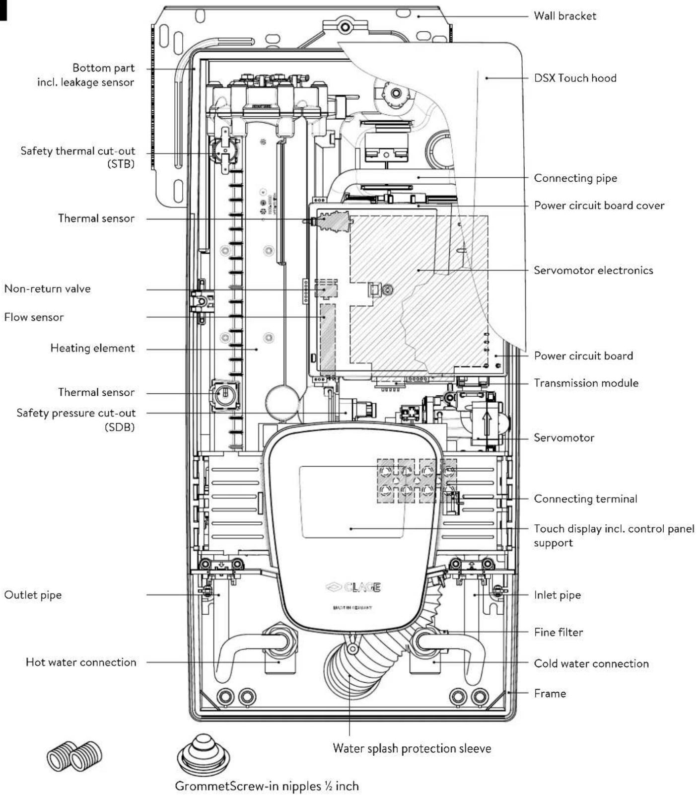
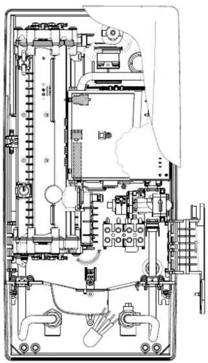
Wall bracket DSX Touch hood Connecting pipe Power circuit board cover Thermal sensor Servomotor electronics Non-return valve Flow sensor Power circuit board Transmission module Heating element Thermal sensor Safety pressure cut-out (SDB) Servomotor Connecting terminal Touch display incl. control panel support Outlet pipe Inlet pipe Hot water connection Fine filter Cold water connection Frame Water splash protection sleeve GrommetScrew-in nipples ½ inch2. Technical specifications
| Model DSX Touch | ||||
| Energy efficiency class A * | 1) | |||
| Rated capacity / rated current 18 kW..27 kW (26 A..39 A) | ||||
| Chosen capacity / current | 18 kW / 26 A | 21 kW / 30 A | 24 kW / 35 A | 27 kW / 39 A |
| Electrical connection | 3~/PE 380..415 V AC | 3~/PE 400 V AC | ||
| Min. required cable size 1) | 4.0 mm2 | 4.0 mm2 | 6.0 mm2 | 6.0 mm2 |
| Hot water (l/min) 2) | ||||
| max. at Δt = 28 K | 9.2 | 10.7 | 12.3 | 13.8 |
| max. at Δt = 38 K | 6.8 | 7.9 | 9.0 | 10.2 |
| Rated volume 0.4 l | ||||
| Rated pressure 1.0 MPa (10 bar) | ||||
| Connecting type | pressure-resistant / pressureless | |||
| Heating system | Bare wire heating system IES® | |||
| @ 15 °C:Required spec. water resistanceSpec. electrical conductivity | ≥ 1100 Ωcm≤ 90 mS/m | |||
| Inlet temperature | ≤ 70 °C | |||
| Switch on - max. flow rate | 1.5 l/min - automatic 3) | |||
| Pressure loss | 0.08 bar at 1.5 l/min 1.3 bar at 9.0 l/min | |||
| Temperature range | 20 - 60 °C [70 °C] | |||
| Water connection | G 1⁄2 inch | |||
| Weight (when filled with water) | 4.5 kg | |||
| Transmission and receiving frequency range Wi-Fi | 2.412 - 2.472 GHz (802.11 b/g/n) | |||
| Transmission power Wi-Fi | ≤ 100 mW | |||
| Transmission and receiving frequency range Bluetooth | 2.4 - 2.4385 GHz | |||
| Transmission power Bluetooth | ≤ 8 mW | |||
| Radiation | undirected | |||
| Transmission range | 10 meter incl. barrier | |||
| VDE class of protection | I | |||
| Type of protection / safety |   IP25 CE IP25 CE | |||
*) The declaration complies with the EU regulation No 812/2013.
1) Maximum applicable cable size is 10 mm^2 in electrical connection from above.
2) Mixed water
3) Electronically controlled depending on the desired temperature and cold water temperature
3. Environment and recycling
This product was manufactured climate neutrally according to Scope 1 + 2. We recommend the purchase of 100% green electricity to make the operation climate neutral as well.
Your product was manufactured from high-quality, reusable materials and components. Please respect in case of discarding that electrical devices should be disposed of separately from household waste at the end of their service life. Therefore, please take this device to a municipal collection point that return used electronic devices to the recycling system. Disposing it correctly will support environmental protection and will prevent any potential negative effects on human beings and the environment that could arise from inappropriate handling of these devices at the end of their service life. Please contact your local authority for further details of your nearest designated collection point or recycling site.
Business customers: If you wish to discard equipment, please contact your dealer or supplier for further information.
4. Dimensions

text_image
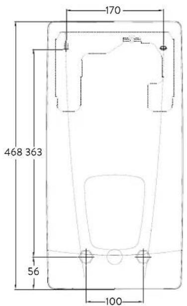
170 468 363 56 100Dimensions in mm
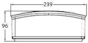
text_image
239 965. Installation
text_image
CLAGE Lüneburg DIN 4109 PA-IX 16952/I MPA NRW.Based on the national constitution guidelines a general test certificate concerning the evidence of applicability of noise behaviour is granted.
The following regulations must be observed:
• e.g. VDE 0100
• EN 806
• Installation must comply with all statutory regulations, as well as those of the local electricity and water supply companies.
• The rating plate and technical specifications
- Only intact and appropriate tools must be used
Installation site
- Appliance must only be installed in frost-free rooms. Never expose appliance to frost.
- The Appliance must be wall mounted and has to be installed with water connectors downward or alternative transversely with water connections left.
- The appliance complies with protection type IP25 and may therefore be installed in protection zone 1 according to VDE 0100 part 701 (IEC 60364-7).
- In order to avoid thermal losses, the distance between the instantaneous water heater and the tap connection should be as small as possible.
• The appliance must be accessible for maintenance work. - Plastic pipes may only be used if they conform to DIN 16893, Series 2.
- The specific resistance of the water must be at least 1100 Ω cm at 15 °C. The specific resistance can be asked for with your water distribution company.
- Do not install the device in the immediate proximity of metal surfaces to allow a reliable wireless connection and an optimal wireless range.
5. Installation
natural_image
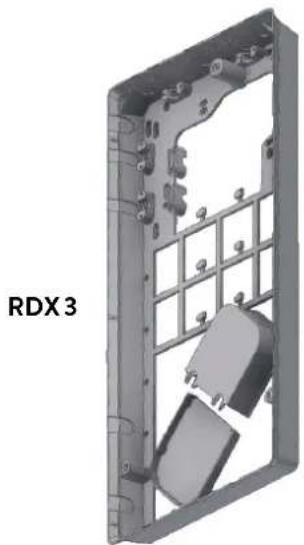
3D CAD model of a mechanical housing or enclosure with internal grid structure and mounting holes (no text or symbols visible)Mounting accessories
For installations under difficult conditions, these mounting accessories are available:
Mounting kit frame RDX 3
(Art. no. 36100)
The instant water heater can be installed by means of this mounting kit when the power supply cable is coming out of the wall at any place from behind the unit, or the wall has unusual surface conditions, making it difficult for installing the water heater.
When using the RDX the protection class changes from IP25 to IP24.
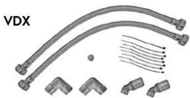
natural_image
Technical illustration of VDX pipe fittings and connectors (no text or symbols)Extension kit VDX
(Art. no. 34120) - RDX / RDX 3 is necessary! -
The instant water heater can be installed by means of this extension kit if the water pipes are coming displaced or exchanged out of the wall or if they are coming edge-wise on the wall to the unit. The power supply could come out of the wall at any place under the unit or the wiring could be installed surface-mounted.
natural_image
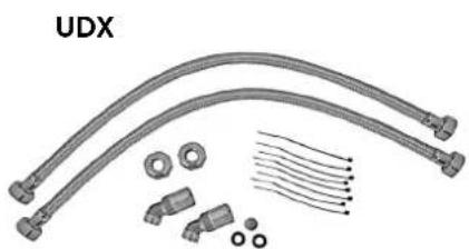
Product assembly of UDX connectors and wiring (no text or symbols visible)Extension kit UDX
(Art. no. 34110) - RDX / RDX 3 is necessary! -
The instant water heater can be installed by means of this extension kit if the water-connections are expiring above the unit. The power supply could come out of the wall at any place under the unit or the wiring could be installed surface-mounted.
5. Installation


text_image
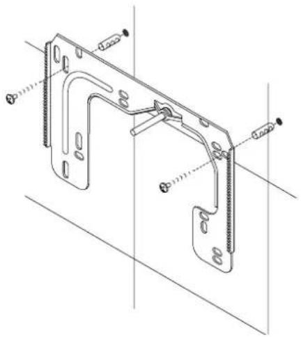
12 G 1/2" 100Installing the wall bracket
Note: If you install this instantaneous water heater in exchange for a conventional instantaneous water heater, there is generally no need to drill holes for the wall bracket, in this case step 2 would not be necessary.
Thoroughly rinse the water supply pipes before installation to remove soiling from the pipes.
- Using a 12 mm hexagon socket screw key, screw the screw-in nipples into the wall connections. The seals must be fully screwed into the thread. After tightening, the double nipples must protrude by 12 – 14 mm.
- Hold the included mounting template on the wall and align it so that the holes in the template fit over the double nipples. Mark the drill holes according to the template and drill them using a 6 mm drill. Insert the included dowels.
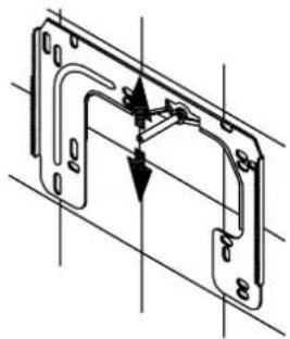
- Pull down the faceplate and unscrew the main hood screw to open the appliance.
- Loosen the knurled nut to remove the wall bracket and screw the wall bracket to the wall. Offset tiling or uneven surfaces can be compensated by up to 30 mm with the aid of the spacers supplied. The spacers are fitted between the wall and the wall bracket.
natural_image
Technical line drawing of a mechanical bracket assembly (no text or symbols)
text_image
warm coldInstalling connection pieces
Note: Fasten the screw nuts with caution, to avoid damage to the valves or the piping system.
- As shown in the illustration, screw the cold water connection piece with the union nut and the 12 inch seal onto the cold water connection.
- Screw the hot water connection piece with the union nut and the 12 inch seal onto the hot water connection.
5. Installation
natural_image
Technical line drawing of an electronic device interior with circuitry and components (no text or symbols)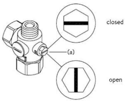
text_image
(a) closed openInstalling the appliance
- The electrical power supply cable may be connected in the upper part or is surface mounted. Only in such case, first follow the steps one through three according to the description "Electrical connection from above" in chapter "Electrical connection".
- Place the appliance on the heater bracket so that the threaded rod of the wall bracket fits in the corresponding hole of the appliance. If necessary, slight corrections are possible by carefully bending the threaded rod of the wall bracket. However, it must be possible to screw on the water connection pipes of the appliance without applying force.
- Screw the plastic knurled nut onto the threaded rod of the wall bracket.
- Screw the two 18 inch union nuts of the appliance's water connection pipes, each with the 38 inch seal, onto the fittings.
natural_image
Technical line drawing of a mechanical bracket assembly (no text or symbols)
text_image
co 30°
text_image
co 30°- Open the water supply line to the unit and slowly open (position "open") the shut-off valve (a) in the cold water connection piece. Check all connections for leaks.
- Next, open and close the hot water tapping valve several times until no more air emerges from the line and all air has been eliminated from the instantaneous water heater.
5. Installation
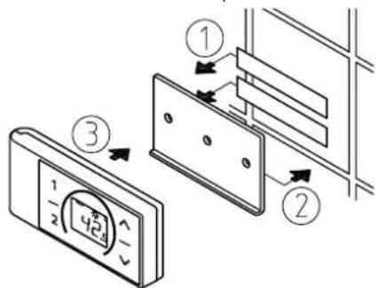
Figure A:
Installation with adhesive tape
text_image
Diagram showing three steps of a device panel installation with numbered annotationsFigure B:
Optional installation with dowels and screws

text_image
Technical diagram showing a digital display panel mounted on a wall-mounted panel, with dimension annotations and component labels.Mounting the remote control's wall bracket
- Before attaching the wall bracket to the wall, ensure that the remote control has radio contact to the instantaneous water heater from its designated position.
- The wall bracket of the remote control can either be attached securely with the included adhesive tape, after stripping off the protection film (as shown in the figure A), on a rigid board (e.g. tile) or with suitable dowels (∅ 4 mm) and screws (as shown in the figure B).
- When mounting with adhesive tape, ensure that the mounting surface is dry and free of grease and soap.
- When using the adhesive tape it is not possible to further adjust the position because of the strong adherence of the glue. Therefore, pay attention to a horizontal alignment when attaching it.
- The remote control is magnetically retained at the wall bracket.
- Keep the remote control and wall bracket away from credit cards or other cards with magnetic strips. The built in magnets can damage the card's magnetic strip.
Note: Do not expose the remote control to moisture.
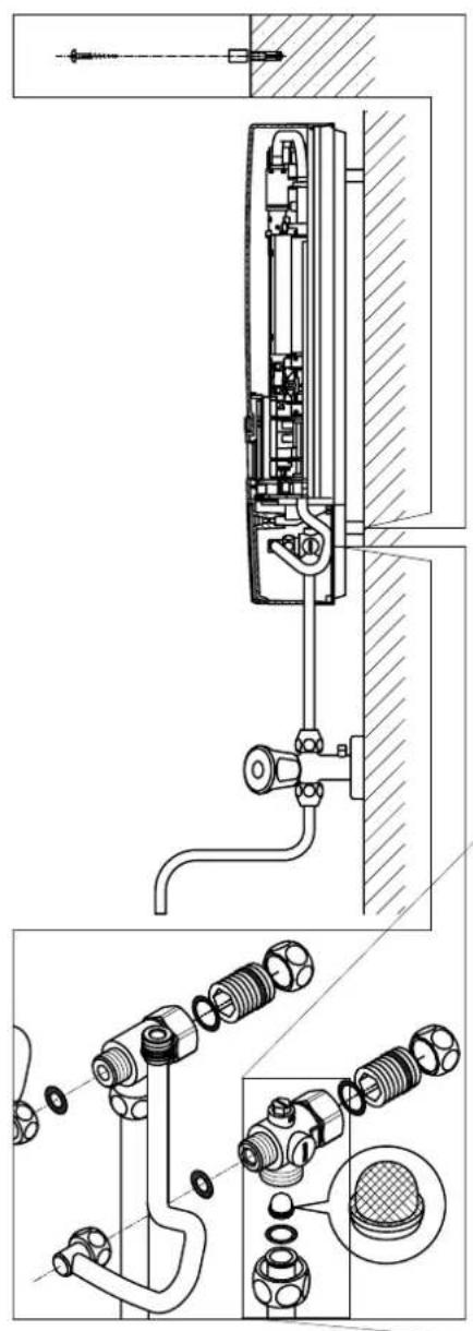
6. Direct connection
natural_image
Technical line drawing of a mechanical assembly with exploded and assembled views (no text or symbols)Note: Fasten the screw nuts with caution, to avoid damage to the valves or the piping system.
For direct connection, the two 12 inch screw-in nipples and the 12 inch seals must be screwed into the 12 inch union nuts of the hot-water and cold-water connectors. The two 12 inch caps of the side outlets of the hot-water and cold-water connectors must be removed and screwed onto the open end of the screw-in nipples. The hot-water and cold-water connectors must then be screwed into the 38 inch union nut of the appliance inlet and outlet pipe, together with the 38 inch seals.
For direct connection, it may be advisable to mount the appliance at a distance as illustrated alongside, using the spacer sleeves supplied. The two fixing holes near the lower pipe connections are also to be professionally fixed with 6 mm dowels and screws.
The flared end of the pipes must be screwed into the 12 inch side outlets of the hot-water and cold-water connectors with 12 inch union nuts and 12 inch seals. The holes required for the pipes must then be opened of the housing with the aid of a blunt implement.
In case of direct connection please note: Put the strainer into the cold water connection!
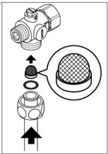
text_image
Technical diagram showing mechanical component assembly with magnified detail view7. Electrical connection
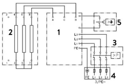
Wiring diagram

text_image
2 3 4 5 6 7 8 9 10 11 12 13 14 15 16 17 18 19 20 21 22 23 24 25 26 27 28 29 30 31 32 33 34 35 36 37 38 39 40 41 42 43 44 45 46 47 48 49 50 51 52 53 54 55 56 57 58 59 60 61 62 63 64 65 66 67 68 69 70 71 72 73 74 75 76 77 78 79 80 81 82 83 84 85 86 87 88 89 90 91 92 93 94 95 96 97 98 99 100- Electronic circuitry
- Heating element
- Safety pressure cut-out
- Connecting terminal
- Safety thermal cut-out
Only by a specialist!
Please observe:
• e.g. VDE 0100
- The installation must comply with current IEC and national local regulations or any particular regulations, specified by the local electricity supply company
• The rating plate and technical specifications
• The appliance must be earthed!
Structural prerequisites
- The appliance must be installed via a permanent connection. Heater must be earthed!
- The electric wiring should not be injured. After mounting, the wiring must not be direct accessible.
- An all-pole disconnecting device (e.g. via fuses) with a contact opening width of at least 3 mm per pole should be provided at the installation end.
- To protect the appliance, a fuse element must be fitted with a tripping current commensurate with the nominal current of the appliance.
Load shedding relay
If further three-phase appliances are connected, a load shedding relay designed for electronic instantaneous water heaters (CLAGE no. 82250) can be connected to phase conductor L2.
To change the operating mode, after making the electrical connection and the initial operation call up the settings menu. Then select the point "Load shedding". If the menu item is grayed out, first activate the "Expert Mode" under Settings/Software.
You can set a value of 0, 1 or 2 bay tabbing < or >
The locking function must be activated then (see chapter "8. Initial operation" sub point "Locking function").
| Value | Description |
| 0 | Operation without load shedding relay, factory setting |
| 1 | Operation with normal load shedding relay |
| 2 | Operation with sensitive load shedding relay |
Operating mode 1 must be selected first, thus to check the correct operation of the load shedding relay at low appliance output (35 degree celsius setpoint and low water flow rate). Mode "2" must be selected if the load shedding relay flickers.

7. Electrical connection

text_image
Technical diagram showing mechanical assembly with labeled components and directional arrows, likely from an engineering or manufacturing context.Electrical connection from below
Note: If necessary, the connecting terminal can be displaced to the upper part of the appliance. If you want to do so, please follow the instructions in the next chapter.
Check that the power supply is switched off prior to electrical connection!
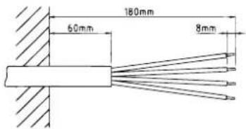
- Dismantle approximately 6 cm off the connecting cable above the wall outlet. With the smaller opening ahead, slide the water splash protection sleeve over the connecting cable so that the sleeve is flush with the wall. This prevents any leaking water from coming into contact with the electrical leads. It must not become damaged! The protection sleeve must be used!
- Open the control panel holder rightwards.
- Strip the cables and plug them in the connecting terminals according to the wiring diagram. The appliance must be earthed.
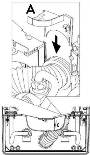
- Pull the protective sleeve over the connecting cables until the sleeve fits perfectly in the recess of the intermediate panel. Adjust the water splash protection sleeve as illustrated and fix it with the sleeve fixing (A). Reinsert the control panel holder and lock it on.
- Place the hood on the appliance and screw in the fastening screw. After that you can slide on the faceplate from the bottom up to the stop.
text_image
180mm 60mm 8mm

natural_image
Technical line drawing of an electrical enclosure with visible wiring and components (no text or labels)Electrical connection from above
Check that the power supply is switched off prior to electrical connection!
- Open the prepared breaking point (S) in the upper part of the appliance by pressing with a blunt implement (e.g. srewdriver). For surface-mounted connection cable additional open the breakout at the right side of the bottom part.
- Slit the grommet to match the cable size. The opening in the grommet should be slightly smaller than the cross-section of the cable in order to ensure optimum protection against water. Fit the grommet into the opening. The protection grommet must be used!
- Strip the connection cable so that the sheath extends through the grommet into the appliance. Hold the prepared appliance in one hand and route the cable into the grommet with the other hand.
- Place the appliance on the wall bracket so that the threaded rod of the wall bracket fits in the corresponding hole of the appliance and fix the appliance.
- Screw the connecting terminal of the adapter cable to the upper connection point. Route the adapter cable past the power section on the left and attach the two brackets to the heating block.
- Open the control panel. Connect the other end of the adapter cable to the lower connecting terminal according to the wiring diagram. Observe outer conductor assignment!
- Strip the individual wires of the connection cable and plug them in the upper connecting terminal according to the wiring diagram. The appliance must be earthed.
- Fold back control panel and lock it in place.
- Place the hood on the appliance and screw in the fastening screw.
Note: To ensure IP25 protection class, please don't remove the bottom water splash protection sleeve.
8. Initial operation

text_image
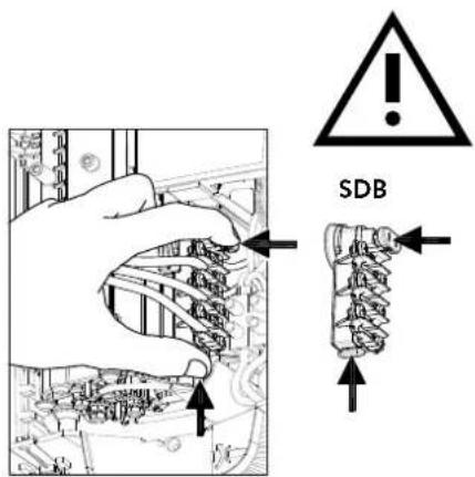
SDB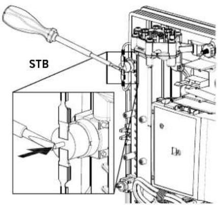
text_image
STB
Multiple Power System MPS®:
The rated capacity (max. power consumption) is 27 kW / 400 V and can be changed internally to 24 kW, 21 kW or 18 kW.
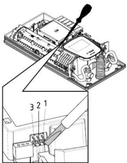
text_image
Technical diagram showing a computer motherboard with labeled parts and a tool inserted, including numbered annotations 1, 2, and 3.Before making the electrical connection, fill the mains and the appliance with water by carefully opening and closing the hot water tap in order to vent completely.
To ensure a maximum flow, remove any existing aerator from the faucet. Flush the warm and cold water pipes each at least for one minute.
After every draining (e.g. after work on the plumbing system or following repairs to the appliance), the heater must be re-vented in this way before starting it up again.
If the water heater cannot be put into operation, the temperature cut-out or the pressure cut-out may have tripped during transport. If necessary, check that the power supply is switched off and reset the cut-out.
Selection of power rating
Only by authorised specialist, otherwise lapse of guarantee!
Upon first connection of the appliance to the supply voltage, select the maximum power rating. Only after having set the power rating, the heater provides its standard operation mode.
The maximum allowable power rating at installation site depends on the local situation. It is imperative to observe all data shown in the table "Technical specifications", in particular the required cable size and fuse protection for the electrical connection. Moreover, the electrical installation must comply with the statutory regulations of the respective country and those of the local electricity supply company (Germany: DIN VDE 0100).
- Switch on the power supply to the appliance.
- When switching on the supply voltage for the first time, the touch screen shows the menu to select the language after about 40 seconds. Choose your language, after that the selection of power rating appears. If not, please follow the note "Reinstallation".
- Select the maximum allowable power rating depending on the local situation via touch (18, 21, 24 or 27 kW).
- Press "OK" to confirm the setting.
- Mark the set power rating on the rating plate.
- After having set the maximum allowable power rating, the heating element will be activated after approx. 10 - 30 sec of continuous water flow.
- Open the hot water tap. Check the function of the appliance.
- Start up the FX3 remote control according to steps 2-6 in chapter "3. Remote control" section "Connecting the remote control to the instantaneous water heater" (see page 41).
- Explain the user how to use the instantaneous water heater and hand over the operating instructions.
- Fill in the guarantee registration card and send it to the CLAGE After-Sales Service or use the online registration on our website (see also page 32).
Reinstallation
In case the appliance will be commis sioned again under different installation conditions than during its initial operation, it may be necessary to adapt the maximum power rating.
A temporary short-circuit of the two pins on the right (see figure), e.g. with a screw-driver acc. to EN 60900, will reset all heater parameters to works setting and lock the heating. The display shows the menu to select the language. Choose your language, after that the selection of power rating appears. This condition will maintain when activating and deactivating the supply voltage.
8. Initial operation
Notes in case of remote control connection problems
In case of a failing connection between the remote control and the water heater, the display indicates "E I". A keystroke restarts the registration.
Under those circumstances reduce the distance to the water heater and check whether the power supply is turned on.
Shower application
The water heater's temperature must be limited to 55 °C, if it is connected to a shower. The temperature limit must be set to a value less or equal 55 °C in the setting menu, in consultation with the customer and the lock level must be activated.
When the appliance is operated with preheated water, it must be ensured that this temperature is limited to 55^ C as well.
text_image
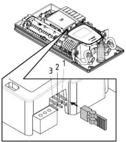
Technical diagram of an electronic device with labeled components and internal wiring, showing exploded and assembled views.
flowchart
graph TD
    A["3"] --> B["2"]
    B --> C["1"]
    D["3"] --> E["2"]
    E --> F["1"]
Pos. OFF Pos. 1
Locking function
The operating mode of the appliance can be restricted.
Activation of the locking function
- Select required parameters via the setting menu (see online user manual chapter "Settings", subpoints "Temperature limit" and / or "Load shedding").
- Disconnect the appliance from the power supply (e.g. by switching off the fuses).
- Take the jumper off the power electronics and change to position "1" (see picture).
- Put the appliance into operation again.
Deactivation of the locking function
- Disconnect the appliance from the power supply (e.g. by switching off the fuses).
- Take the jumper off the power electronics and change to position "OFF" (see picture).
- Put the appliance into operation again.
9. Maintenance work
Maintenance work must only be conducted by an authorised professional.
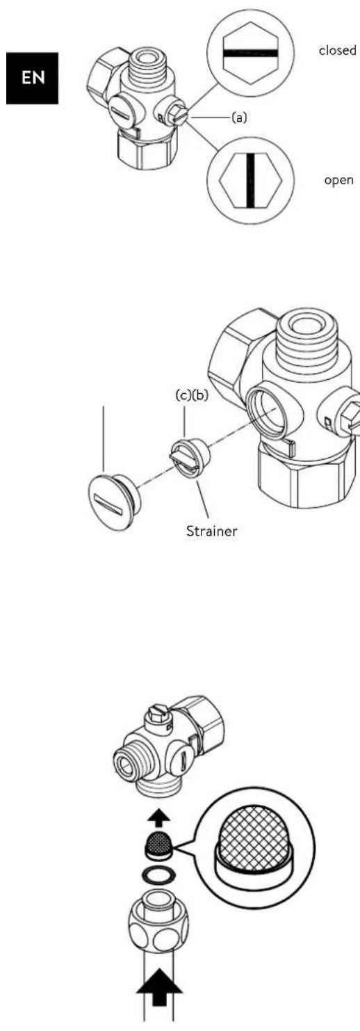
Cleaning and replacing the filter strainer
The cold water connection of this instantaneous water heater is equipped with an integrated shut-off valve and a strainer. Soiling of the strainer may reduce the warm water output. Clean or replace the strainer as follows:
- De-energize the instantaneous water heater (e.g. via deactivating the fuses) and prevent inadvertent reactivation of them.
- To open the appliance, take off the small face plate, loose the screw behind this cover and detach the hood.
- Close the shut-off valve (a) in the cold water connection piece (position "closed").
- Unscrew the screw plug (b) from the cold water connection piece and take out the strainer (c). Note: Residual water can leak
- The strainer can now be cleaned or replaced.
- After fitting of the clean strainer tighten the screw plug.
- Slowly reopen the shut-off valve in the cold water connection piece (position "open"). Check all connections for leaks.
- Vent the appliance by carefully opening and closing the affiliated warm water tap valve several times until air no longer emerges from the pipe.
- Fit the hood of the appliance. Then switch on the power again (e.g. via activating the fuses).
Cleaning and replacing the filter strainer if direct connected
The cold water connection of this instantaneous water heater is equipped with a strainer. Soiling of the strainer may reduce the warm water output. Clean or replace the strainer as follows:
- De-energize the instantaneous water heater (e.g. via deactivating the fuses) and prevent inadvertent reactivation of them.
- Close the shut-off valve in the mains water supply of the instantaneous water heater.
- To open the appliance, take off the small face plate, loose the screw behind this cover and detach the hood.
- Unscrew mains water inlet from connection piece and take out the strainer. Note: Residual water can leak
- The strainer can now be cleaned or replaced.
- After refitting the clean strainer reconnect the mains water inlet to the connection piece.
- Slowly reopen the shut-off valve in the mains water supply. Check all connections for leaks.
- Vent the appliance by carefully opening and closing the affiliated warm water tap valve several times until air no longer emerges from the pipe.
- Fit the hood of the appliance. Then switch on the power again (e.g. via activating the fuses).
Sommaire
natural_image
White cylindrical water heater with digital display showing 38 seconds and control buttons (no text or symbols on main body)CE
natural_image
Simple black-and-white line drawing of a tree with two horizontal lines below (no text or symbols)text_image
Technical diagram showing three-step installation of a wall-mounted device with labeled components and directional arrows.text_image
Technical diagram showing a digital display panel connected to a wall-mounted panel with dimension annotationstext_image
Warning symbol with exclamation mark inside trianglenatural_image
3D CAD model of a mechanical housing frame with internal compartments and mounting holes (no text or symbols)natural_image
Product diagram of VDX connectors and tubing (no text or symbols)natural_image
Product diagram of UDX connectors and wiring components (no text or symbols)natural_image
Technical line drawing of a mechanical bracket assembly (no text or symbols)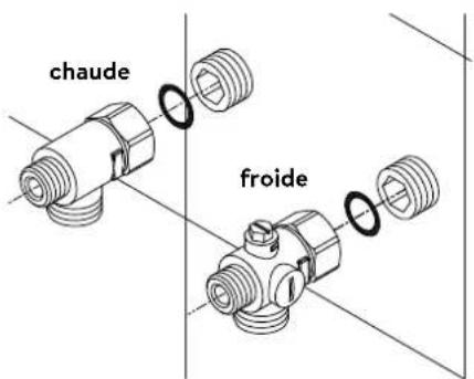
text_image
chaude froidePose des raccords
natural_image
Technical line drawing of an electronic device interior with circuitry and components (no text or symbols)natural_image
Technical line drawing of a mechanical bracket assembly with no visible text or symbols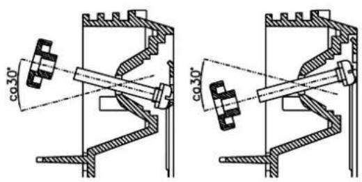
text_image
co30° co30°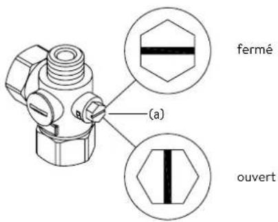
text_image
Diagram showing three steps of installing a wall-mounted panel, with numbered annotations indicating component placement.text_image
Technical diagram showing a digital display panel mounted on a wall-mounted panel, with dimension annotations and alignment markers.natural_image
Technical line drawing of a mechanical assembly with exploded and assembled views (no text or symbols)text_image
Technical diagram showing mechanical assembly with labeled components and a magnified inset of a textured componenttext_image
Technical diagram showing mechanical assembly with labeled components and directional arrows, likely illustrating a gear or turbine mechanism.text_image
180mm 60mm 8mmnatural_image
Technical line drawing of an electrical enclosure with warning symbol (no text or labels)text_image
Technical diagram showing a device with labeled parts and a tool inserted, including numbered annotations 1, 2, and 3.Remise en service
text_image
Technical diagram showing internal components of a device with numbered parts and an arrow indicating assembly or connection.Pos. ARRÊT Pos. 1
text_image
Technical diagram showing a mechanical component with a close-up view of its cross-section, likely illustrating a mechanical assembly or assembly process.https://partner.clage.com/en/service/device-registration/
Instructies
natural_image
White cylindrical water heater with digital display showing 38 seconds and control buttons (no text or symbols on main body)CE
text_image
Mobile app interface with icons for cleaning, a shower, and a numeric display showing '38'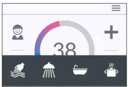
text_image
38Statusweergave hierboven
text_image
Main Menu Automatic User Statistics Savings Settings Infotext_image
Automatic Duration START < 1 min > Fill-Up START < 100 l > To define fill-up quantity see Statistics Consumption last tapping.Automaat "Automatic"
text_image
Temperature Limit Temperature Limit ON Max. Temperature < 53 > The Temperature Limit is set to 60°C at factory. Here you can limit the maximum outlet temperature of the appliance.text_image
Operation Lock Enter PIN > Protected Sections > Delete PIN >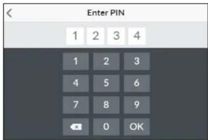
text_image
Enter PIN 1 2 3 4 1 2 3 4 5 6 7 8 9 OK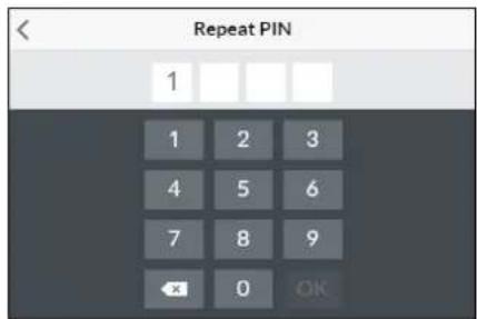
text_image
Repeat PIN 1 1 2 3 4 5 6 7 8 9 OK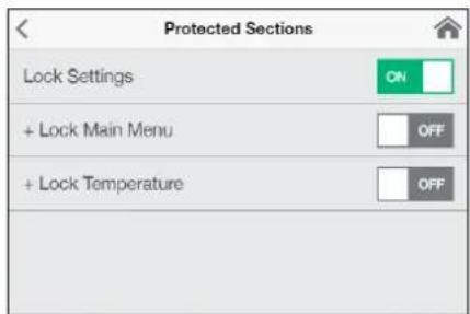
text_image
Protected Sections Lock Settings ON + Lock Main Menu OFF + Lock Temperature OFFtext_image
< Brightness Operation < 70 > Standby < 5 >text_image
Device Information Power Consumption 0.0 kW Flow Rate 0 l/min Outlet Temperature 0.0 °C Inlet Temperature 0.0 °C Demand 0 kWInfo "Info"
natural_image
Simple black-and-white line drawing of a tree with two horizontal lines below (no text or symbols)text_image
Technical diagram showing three-step installation of a wall-mounted device with labeled components and directional arrows.Afbeelding B:
text_image
Technical diagram showing a digital display panel connected to a wall-mounted panel with dimension annotations and numbered components.Monteer de muurbeugel
| Devices | |
| Searching Home Servers... | |
| Setup Home Server manually | > |
| Bluetooth Interface | > |
| Setup Assistant | > |
| Demo Mode | OFF |
B
| Devices | |
| No devices found. | |
| Setup Home Server manually | > |
| Bluetooth Interface | > |
| DFX_4521201101052108/16/2021 12:10:18 | + |
| DSX_06212049FFEE2208/16/2021 12:10:18 | + |
| Setup Assistant | > |
| Demo Mode | OFF |
| < | Connect Device |
| In order to connect to your device, please scan the QR Code on the device or enter the Bluetooth PIN manually. | |
| Scan QR Code > | |
| Enter PIN > |
text_image
Advanced WLAN ON Operation Mode Client > The Home Server is connected to your existing WIFI- Network. Network CLAGE_DE > PasswordVerbinding via WLAN
text_image
Advanced WLAN ON Operation Mode Client > The Home Server is connected to your existing WIFI- Network. Network CLAGE_DE > PasswordWLAN uitschakelen
text_image
Software Update Current Version DSX3CP-v1.1.0 This system can be updated. Install UpdateUpdate van de DSX Touch-software
text_image
Warning symbol with exclamation mark inside trianglenatural_image
3D CAD model of a mechanical housing frame with internal compartments and mounting holes (no text or symbols)Montagetoebehoren
natural_image
Product diagram of VDX connectors and terminal blocks (no text or symbols)Buizenset VDX
(artikelnummer 34120) - RDX / RDX 3 vereist! -
natural_image
Product assembly of flexible hose connectors and connector parts (no text or symbols visible)Buizenset UDX
(artikelnummer 34110) - RDX / RDX 3 vereist! -
natural_image
Technical line drawing of a mechanical bracket assembly (no text or symbols)
text_image
warm koudnatural_image
Technical line drawing of an electronic device interior with circuitry and components (no text or symbols)
text_image
(a) gesloten geopendApparaat monteren
natural_image
Technical line drawing of a mechanical bracket assembly with mounting holes and internal components (no text or symbols)
text_image
co30°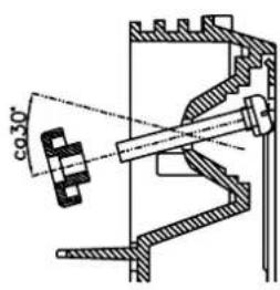
text_image
co 30°text_image
Diagram showing three steps of installing a wall-mounted panel, with numbered annotations indicating component placement.Afbeelding B:
text_image
Technical diagram showing a door panel mounted on a wall-mounted device with dimension annotations and control points.natural_image
Technical line drawing of a mechanical assembly with exploded and assembled views (no text or symbols)text_image
Technical diagram showing mechanical component assembly with magnified detail viewtext_image
Technical diagram showing mechanical assembly with labeled components and directional arrows, likely illustrating a process or assembly.text_image
180mm 60mm 8mmnatural_image
Technical line drawing of an electrical enclosure with warning symbol (no text or labels)Multiple Power System MPS®:
text_image
Technical diagram showing a disassembled electronic device with labeled parts and a tool inserted into it.text_image
Technical diagram showing internal components of a device with numbered parts and an arrow indicating assembly or connection.Pos. UIT Pos. 1
text_image
Technical diagram showing a mechanical component with cross-sectional view and directional arrows indicating assembly or assembly process.Controlo principal 123
Menu principal 124
Trocar as pilhas....132
Eliminação.... 132
- CLAGE app "Smart Control" 133
https://partner.clage.com/en/service/device-registration/
natural_image
White industrial water heater with digital display showing 38-degree rotary dial and control buttons (no text or symbols on main body)text_image
Main Menu Automatic User Statistics Savings Settings InfoMenu principal
text_image
Automatic Duration START < 1 min > Fill-Up START < 1001 > To define fill-up quantity see Statistics Consumption last tapping.text_image
Temperature Limit Temperature Limit ON Max. Temperature < 53 > The Temperature Limit is set to 60°C at factory. Here you can limit the maximum outlet temperature of the appliance.2. Utilização

text_image
Operation Lock Enter PIN > Protected Sections > Delete PIN >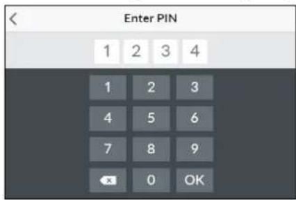
text_image
Enter PIN 1 2 3 4 1 2 3 4 5 6 7 8 9 OK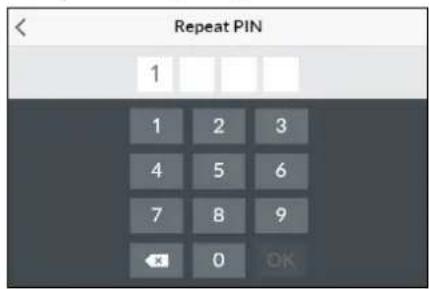
text_image
Repeat PIN 1 1 2 3 4 5 6 7 8 9 OK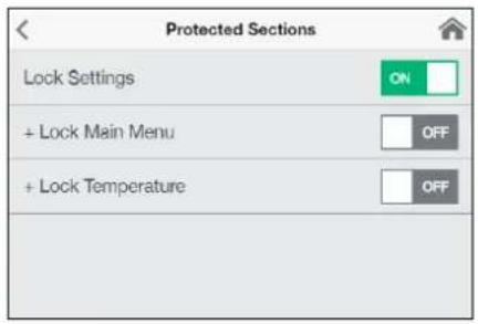
text_image
Protected Sections Lock Settings ON + Lock Main Menu OFF + Lock Temperature OFFtext_image
Brightness Operation < 70 > Standby < 5 >text_image
Device Information Power Consumption 0.0 kW Flow Rate 0 l/min Outlet Temperature 0.0 °C Inlet Temperature 0.0 °C Demand 0 kWInformações "Info"
natural_image
Simple black-and-white line drawing of a tree with two roots and a cloud at the top (no text or symbols)text_image
Diagram showing three steps of a door panel installation with numbered annotationstext_image
Technical diagram showing a door panel mounted on a wall with dimension annotations and a digital display screen.Montar o suporte de parede
4. CLAGE app "Smart Control"
A
| Devices | |
| Searching Home Servers... | |
| Setup Home Server manually | > |
| Bluetooth Interface | > |
| Setup Assistant | > |
| Demo Mode | OFF |
B
| Devices | |
| No devices found. | |
| Setup Home Server manually | > |
| Bluetooth Interface | > |
| DFX_4521201101052108/16/2021 12:10:18 | + |
| DSX_06212049FFEE2208/16/2021 12:10:18 | + |
| Setup Assistant | > |
| Demo Mode | OFF |
| < | Connect Device |
| In order to connect to your device, please scan the QR Code on the device or enter the Bluetooth PIN manually. | |
| Scan QR Code > | |
| Enter PIN > |
| WLAN | |
| Operation Mode | Client > |
| The Home Server is connected to your existing WIFI-Network. | |
| Network | CLAGE_DE > |
| Password | |
4. CLAGE app "Smart Control"
text_image
Advanced WLAN ON Operation Mode Client > The Home Server is connected to your existing WIFI- Network. Network CLAGE_DE > Password4. CLAGE app "Smart Control"
| < | Software Update |
| Current Version | DSX3CP-v1.1.0 |
| This system can be updated. | |
| Install Update | |
text_image
Warning symbol with exclamation mark inside trianglenatural_image
3D CAD model of a mechanical housing or enclosure with internal grid structure and mounting holes (no text or symbols visible)natural_image
Product assembly of UDX connectors and wiring (no text or symbols visible)Kit de extensão UDX
(Art.-Nr. 34110) - O RDX / RDX 3 é necessário! -
natural_image
Technical line drawing of a mechanical bracket assembly (no text or symbols)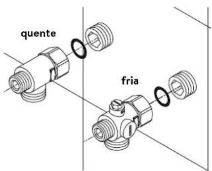
text_image
quente frianatural_image
Technical line drawing of an electronic device interior with circuitry and components (no text or symbols)natural_image
Technical line drawing of a mechanical bracket assembly with no visible text or symbols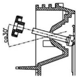
text_image
co30°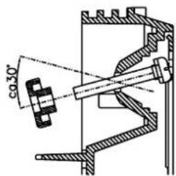
text_image
co 30°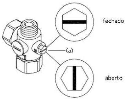
text_image
fechado (a) abertotext_image
Diagram showing three steps of a device panel installation with numbered annotationsnatural_image
Technical line drawing of a mechanical assembly with exploded and assembled views (no text or symbols)text_image
Technical diagram showing mechanical assembly with labeled components and a magnified inset of a textured component7. Ligação elétrica
Diagrama elétrico
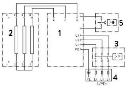
text_image
2 4 6 8 1 5 L3 L2 L1 PE 3 P 4 3/PE~text_image
180mm 60mm 8mm
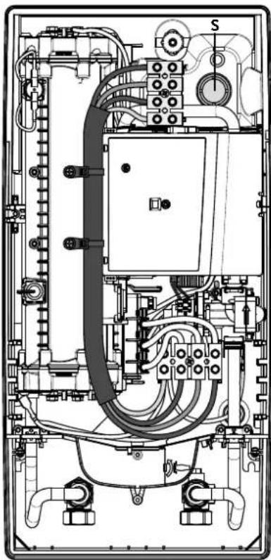
natural_image
Technical line drawing of an electrical enclosure with visible wiring, switches, and components (no text or labels)Multiple Power System MPS®:
text_image
Technical diagram showing a computer motherboard with labeled parts and a tool inserted, including numbered annotations 1, 2, and 3.text_image
Technical diagram of a device with labeled components, showing internal structure and assembly steps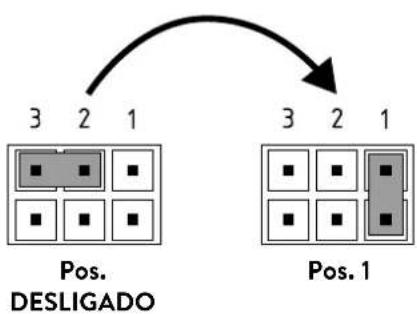
flowchart
graph TD
    A["Pos. DESLIGADO"] --> B["3 2 1"]
    B --> C["Pos. 1"]
    C --> D["3 2 1"]
Bloqueio
text_image
Technical diagram showing a mechanical component with an inset close-up of a textured surface, illustrating assembly or assembly process.Control principal 153
Menú principal 154
https://partner.clage.com/en/service/device-registration/
natural_image
White industrial water heater with digital display showing 38°C and control buttons (no text or symbols beyond branding)text_image
Main Menu Automatic User Statistics Savings Settings Info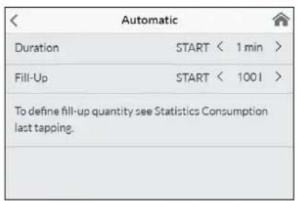
text_image
Automatic Duration START < 1 min > Fill-Up START < 100 l > To define fill-up quantity see Statistics Consumption last tapping.
text_image
38 01:43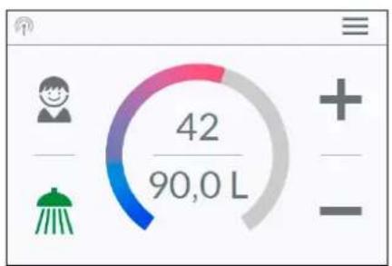
gauge
| Value | |-------| | 42/90,0 L |text_image
Temperature Limit Temperature Limit ON Max. Temperature < 53 > The Temperature Limit is set to 60°C at factory. Here you can limit the maximum outlet temperature of the appliance.text_image
Operation Lock Enter PIN > Protected Sections > Delete PIN >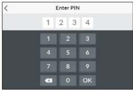
text_image
Enter PIN 1 2 3 4 1 2 3 4 5 6 7 8 9 OK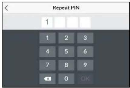
text_image
Repeat PIN 1 1 2 3 4 5 6 7 8 9 OK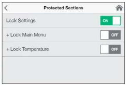
text_image
Protected Sections Lock Settings ON + Lock Main Menu OFF + Lock Temperature OFFtext_image
Brightness Operation < 70 > Standby < 5 >Ajuste de fábrica "Factory Settings": All factory settings can be recalled:
text_image
Device Information Power Consumption 0.0 kW Flow Rate 0 l/min Outlet Temperature 0.0 °C Inlet Temperature 0.0 °C Demand 0 kWInformación "Info"
natural_image
Simple black-and-white line drawing of a tree with two roots and a cloud at the top (no text or symbols)text_image
Diagram showing three-step installation of a digital timer with numbered components and directional arrows indicating assembly steps.text_image
Technical diagram showing a digital display panel connected to a wall-mounted panel with dimension annotations4. CLAGE app "Smart Control"
A
| Devices | |
| Searching Home Servers... | |
| Setup Home Server manually | > |
| Bluetooth Interface | > |
| Setup Assistant | > |
| Demo Mode | OFF |
B
| Devices | |
| No devices found. | |
| Setup Home Server manually | > |
| Bluetooth Interface | > |
| DFX_4521201101052108/16/2021 12:10:18 | + |
| DSX_06212049FFEE2208/16/2021 12:10:18 | + |
| Setup Assistant | > |
| Demo Mode | OFF |
| < | Connect Device |
| In order to connect to your device, please scan the QR Code on the device or enter the Bluetooth PIN manually. | |
| Scan QR Code > | |
| Enter PIN > |
| Advanced | |
| WLAN | ON |
| Operation Mode | Client > |
| The Home Server is connected to your existing WIFI-Network. | |
| Network | CLAGE_DE > |
| Password | |
4. CLAGE app "Smart Control"
text_image
Advanced WLAN ON Operation Mode Client > The Home Server is connected to your existing WIFI- Network. Network CLAGE_DE > Password4. CLAGE app "Smart Control"
| < | Software Update |
| Current Version | DSX3CP-v1.1.0 |
| This system can be updated. | |
| Install Update | |
text_image
Warning symbol with exclamation mark inside trianglenatural_image
3D mechanical assembly diagram showing internal components and mounting holes (no text or symbols)natural_image
Product assembly of UDX connectors and wiring (no text or symbols visible)natural_image
Technical line drawing of a mechanical bracket assembly (no text or symbols)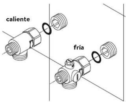
natural_image
Technical line drawing of an electronic device interior with circuitry and components (no text or symbols)Montar el equipo
natural_image
Technical line drawing of a mechanical bracket assembly with no visible text or symbols
text_image
co.30° co.30°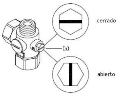
text_image
Diagram showing three steps of installing a wall-mounted panel, with numbered annotations indicating component placement.text_image
Technical diagram showing a door panel mounted on a wall-mounted device with dimension annotations and control points.natural_image
Technical line drawing of a mechanical assembly with exploded and assembled views (no text or symbols)text_image
Technical diagram showing mechanical assembly with labeled components and a magnified inset of a component detailtext_image
180mm 60mm 8mm
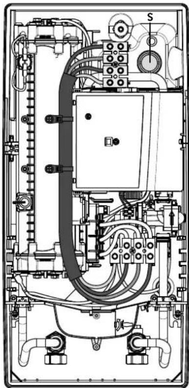
natural_image
Technical line drawing of an electrical enclosure with visible wiring and components (no text or labels)Multiple Power System MPS®:
text_image
Technical diagram showing a computer motherboard with labeled components and a tool inserted, including parts numbered 1, 2, and 3.text_image
Technical diagram of an electronic device with labeled components and internal wiring, showing exploded and assembled views.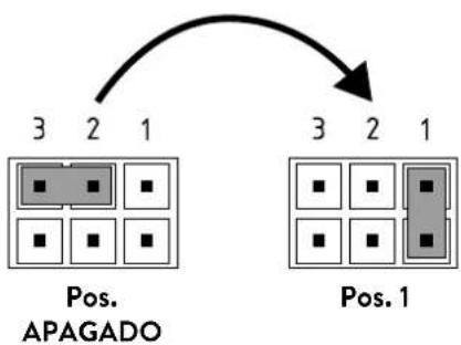
flowchart
graph TD
    A["Pos. 3,2,1"] --> B["Pos. 2,3,4,5,6,7,8"]
    C["Pos. 3,2,1"] --> D["Pos. 1,2,3,4,5,6,7"]
Función de bloqueo
text_image
(c)(b) Tamiz
text_image
Technical diagram showing a mechanical component with an inset close-up of a textured surface, annotated with directional arrows and cross-sections.natural_image
White industrial water heater with digital display showing 38°C and control buttons (no text or symbols beyond branding)text_image
Two digital interface screenshots showing a shower gauge and a circular progress indicator with '38' text.Zastosowania
text_image
Main Menu Automatic User Statistics Savings Settings Info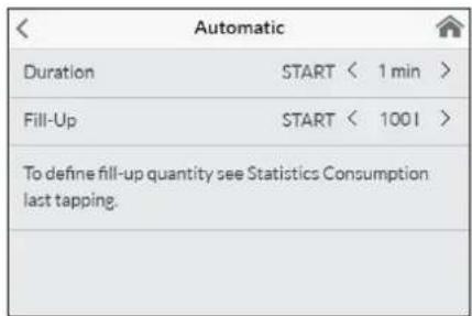
text_image
Automatic Duration START < 1 min > Fill-Up START < 1001 > To define fill-up quantity see Statistics Consumption last tapping.
gauge
| Metric | Value | |--------|-------| | Current | 38 | | 01:43 | 38 |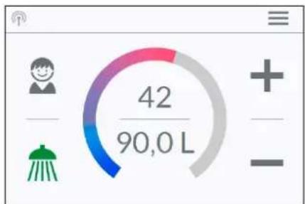
gauge
| Category | Value | | -------- | ----- | | Current | 42/90,0 L |text_image
Temperature Limit Temperature Limit ON Max. Temperature < 53 > The Temperature Limit is set to 60°C at factory. Here you can limit the maximum outlet temperature of the appliance.text_image
Operation Lock Enter PIN > Protected Sections > Delete PIN >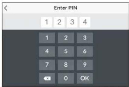
text_image
Enter PIN 1 2 3 4 1 2 3 4 5 6 7 8 9 OK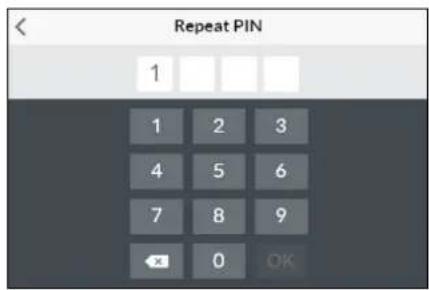
text_image
Repeat PIN 1 1 2 3 4 5 6 7 8 9 ← 0 OK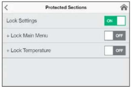
text_image
Protected Sections Lock Settings ON + Lock Main Menu OFF + Lock Temperature OFFtext_image
Brightness Operation < 70 > Standby < 5 >text_image
Device Information Power Consumption 0.0 kW Flow Rate 0 V/min Outlet Temperature 0.0 °C Inlet Temperature 0.0 °C Demand 0 kWnatural_image
Simple black-and-white line drawing of a tree with two wavy lines at the base (no text or symbols)text_image
Diagram showing three steps of installing a digital display panel with numbered annotationsRysunek B:
| Devices | |
| Searching Home Servers... | |
| Setup Home Server manually | > |
| Bluetooth Interface | > |
| Setup Assistant | > |
| Demo Mode | OFF |
B
| Devices | |
| No devices found. | |
| Setup Home Server manually | > |
| Bluetooth Interface | > |
| DFX_4521201101052108/16/2021 12:10:18 | + |
| DSX_06212049FFEE2208/16/2021 12:10:18 | + |
| Setup Assistant | > |
| Demo Mode | OFF |
| < | Connect Device |
| In order to connect to your device, please scan the QR Code on the device or enter the Bluetooth PIN manually. | |
| Scan QR Code > | |
| Enter PIN > |
text_image
Advanced WLAN ON Operation Mode Client > The Home Server is connected to your existing WIFI- Network. Network CLAGE_DE > Password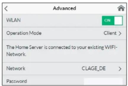
text_image
Advanced WLAN ON Operation Mode Client > The Home Server is connected to your existing WIFI- Network. Network CLAGE_DE > Password| < | Software Update |
| Current Version | DSX3CP-v1.1.0 |
| This system can be updated. | |
| Install Update | |
text_image
Warning symbol with exclamation mark inside trianglenatural_image
3D CAD model of a mechanical housing or enclosure with internal grid structure and mounting holes (no text or symbols visible)Akcesoria montażowe
natural_image
Product assembly diagram of UDX connectors and wiring (no text or symbols)natural_image
Technical line drawing of a mechanical bracket assembly (no text or symbols)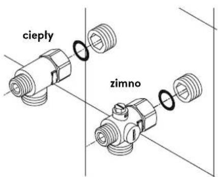
text_image
cieply zimnonatural_image
Technical line drawing of an electronic device interior with circuitry and components (no text or symbols)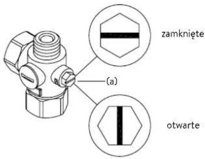
natural_image
Technical line drawing of a mechanical bracket assembly (no text or symbols)
text_image
co30°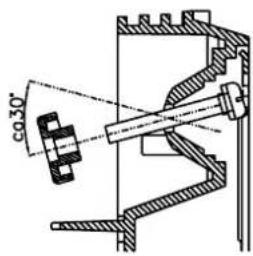
text_image
co 30°text_image
Diagram showing three steps of a door panel installation with numbered annotationsRysunek B:
natural_image
Technical line drawing of a mechanical assembly with exploded and assembled views (no text or symbols)text_image
Technical diagram showing mechanical assembly with labeled components and a magnified inset of a textured componenttext_image
Technical diagram showing mechanical assembly with labeled components and directional arrows, likely from an engineering or manufacturing context.text_image
180mm 60mm 8mm

natural_image
Technical line drawing of an electrical enclosure with visible wiring and components (no text or labels)Multiple Power System MPS®:
text_image
Technical diagram showing a computer motherboard with labeled parts and a tool inserted, including numbered annotations 1, 2, and 3.text_image
Technical diagram of an electronic device with labeled components and internal wiring, showing exploded and assembled views.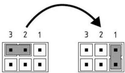
flowchart
graph TD
    A["3"] --> B["2"]
    B --> C["1"]
    D["3"] --> E["2"]
    E --> F["1"]
Pos. WYL Pos. 1
Funkcja blokady
text_image
Technical diagram showing a mechanical component with cross-sectional view and directional arrows indicating assembly or assembly process.https://partner.clage.com/en/service/device-registration/
natural_image
White industrial water heater with digital display showing 38% change, no visible text or symbols on the device itself.text_image
Main Menu Automatic User Statistics Savings Settings Info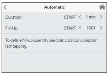
text_image
Automatic Duration START < 1 min > Fill-Up START < 1001 > To define fill-up quantity see Statistics Consumption last tapping.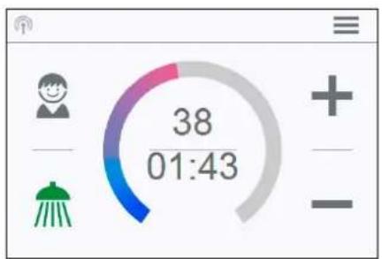
text_image
38 01:43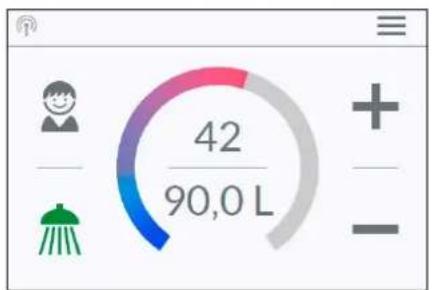
text_image
42 90,0 Ltext_image
Temperature Limit Temperature Limit ON Max. Temperature < 53 > The Temperature Limit is set to 60°C at factory. Here you can limit the maximum outlet temperature of the appliance.text_image
Operation Lock Enter PIN > Protected Sections > Delete PIN >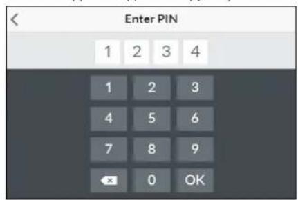
text_image
Enter PIN 1 2 3 4 1 2 3 4 5 6 7 8 9 OK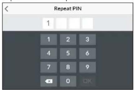
text_image
Repeat PIN 1 1 2 3 4 5 6 7 8 9 OK
text_image
Protected Sections Lock Settings ON + Lock Main Menu OFF + Lock Temperature OFFtext_image
< Brightness Operation < 70 > Standby < 5 >text_image
Device Information Power Consumption 0.0 kW Flow Rate 0 l/min Outlet Temperature 0.0 °C Inlet Temperature 0.0 °C Demand 0 kWСведения "Info"
natural_image
Simple black-and-white line drawing of a tree with two horizontal lines below (no text or symbols)text_image
Diagram showing three steps of installing a digital display panel with numbered annotations| Devices | |
| Searching Home Servers... | |
| Setup Home Server manually | > |
| Bluetooth Interface | > |
| Setup Assistant | > |
| Demo Mode | OFF |
B
| Devices | |
| No devices found. | |
| Setup Home Server manually | > |
| Bluetooth Interface | > |
| DFX_4521201101052108/16/2021 12:10:18 | + |
| DSX_06212049FFEE2208/16/2021 12:10:18 | + |
| Setup Assistant | > |
| Demo Mode | OFF |
| < | Connect Device |
| In order to connect to your device, please scan the QR Code on the device or enter the Bluetooth PIN manually. | |
| Scan QR Code > | |
| Enter PIN > |
| Advanced | |
| WLAN | ON |
| Operation Mode | Client > |
| The Home Server is connected to your existing WIFI-Network. | |
| Network | CLAGE_DE > |
| Password | |
Начало эксплуатации
text_image
Advanced WLAN Operation Mode Client > The Home Server is connected to your existing WIFI- Network. Network CLAGE_DE > Passwordtext_image
Warning symbol with exclamation mark inside trianglenatural_image
3D mechanical assembly diagram showing internal components and mounting holes (no text or symbols)natural_image
Technical illustration of VDX pipe fittings and connectors (no text or symbols)natural_image
Product assembly of UDX connectors and wiring (no text or symbols visible)natural_image
Technical line drawing of a mechanical bracket assembly (no text or symbols)natural_image
Technical line drawing of an electronic device interior with circuitry and components (no text or symbols)Монтаж нагревателя
natural_image
Technical line drawing of a mechanical bracket assembly (no text or symbols)
text_image
co 30°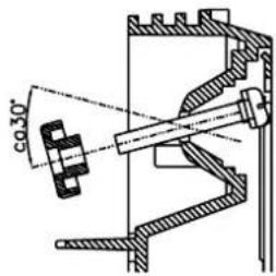
text_image
co 30°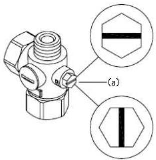
text_image
(a)закрыто
открыто
text_image
Diagram showing three steps of installing a wall-mounted panel, with numbered annotations indicating component placement.Рисунок В.
text_image
Technical diagram showing a digital display panel mounted on a wall-mounted panel with dimension annotations and control points.natural_image
Technical line drawing of a mechanical assembly with exploded and assembled views (no text or symbols)text_image
Technical diagram showing mechanical component assembly with magnified detail view highlighting a textured componenttext_image
180mm 60mm 8mm
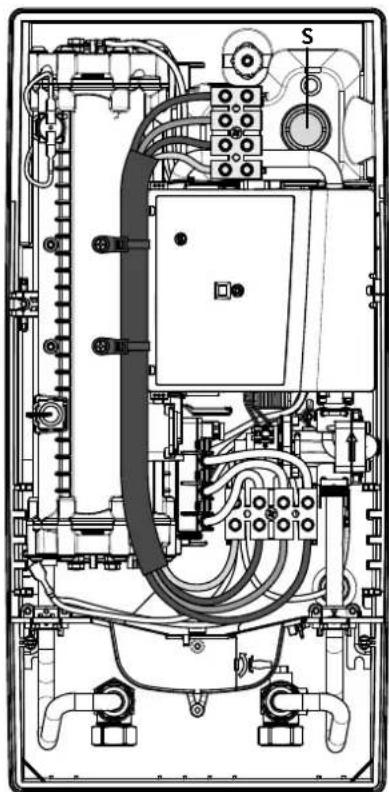
natural_image
Technical line drawing of an electrical enclosure with visible wiring and components (no text or labels)text_image
Technical diagram showing a disassembled electronic device with labeled parts and a tool inserted into it.text_image
Technical diagram of an electronic device with labeled components and internal wiring, showing exploded and assembled views.Функция блокировки
text_image
Technical diagram showing a mechanical component with an inset close-up of a textured surface, illustrating assembly or assembly process.https://partner.clage.com/en/service/device-registration/
Návod k obsluze
natural_image
White industrial water heater with digital display showing 38°C and control buttons (no text or symbols beyond branding)text_image
Main Menu Automatic User Statistics Savings Settings InfoHlavní menu
text_image
Automatic Duration START < 1 min > Fill-Up START < 1001 > To define fill-up quantity see Statistics Consumption last tapping.text_image
Temperature Limit Temperature Limit ON Max. Temperature < 53 > The Temperature Limit is set to 60°C at factory. Here you can limit the maximum outlet temperature of the appliance.text_image
Operation Lock Enter PIN > Protected Sections > Delete PIN >text_image
Protected Sections Lock Settings ON + Lock Main Menu OFF + Lock Temperature OFFtext_image
Brightness Operation < 70 > Standby < 5 >text_image
Device Information Power Consumption 0.0 kW Flow Rate 0 l/min Outlet Temperature 0.0 °C Inlet Temperature 0.0 °C Demand 0 kWnatural_image
Simple black-and-white line drawing of a tree with two wavy lines at the base (no text or symbols)text_image
Diagram showing three steps of a digital display panel installation, labeled 1, 2, and 3 with arrows indicating direction.Obrázek B:
text_image
Technical diagram showing a digital display panel connected to a wall-mounted panel with dimension annotations4. CLAGE app "Smart Control"
A
| < Devices | |
| Searching Home Servers... | |
| Setup Home Server manually | > |
| Bluetooth Interface | > |
| Setup Assistant | > |
| Demo Mode | OFF |
B
| Devices | |
| No devices found. | |
| Setup Home Server manually | > |
| Bluetooth Interface | > |
| DFX_4521201101052108/16/2021 12:10:18 | + |
| DSX_06212049FFEE2208/16/2021 12:10:18 | + |
| Setup Assistant | > |
| Demo Mode | OFF |
| < | Connect Device |
| In order to connect to your device, please scan the QR Code on the device or enter the Bluetooth PIN manually. | |
| Scan QR Code > | |
| Enter PIN > |
| Advanced | |
| WLAN | ON |
| Operation Mode | Client > |
| The Home Server is connected to your existing WIFI-Network. | |
| Network | CLAGE_DE > |
| Password | |
4. CLAGE app "Smart Control"

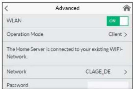
text_image
Advanced WLAN ON Operation Mode Client > The Home Server is connected to your existing WIFI- Network. Network CLAGE_DE > Password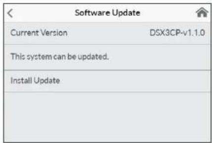
text_image
Software Update Current Version DSX3CP-v1.1.0 This system can be updated. Install Updatetext_image
Warning symbol with exclamation mark inside trianglenatural_image
3D mechanical assembly diagram showing internal components and mounting holes (no text or symbols)natural_image
Technical illustration of VDX pipe fittings and connectors (no text or symbols)Sada k instalaci potrubí VDX
natural_image
Product assembly of flexible hose connectors and connectors (no text or symbols visible)Sada k instalaci potrubí UDX
natural_image
Technical line drawing of a mechanical bracket assembly (no text or symbols)
text_image
teplé zimanatural_image
Technical line drawing of an electronic device interior with circuitry and components (no text or symbols)Montáž prístroje
natural_image
Technical line drawing of a mechanical bracket assembly (no text or symbols)
text_image
co 30°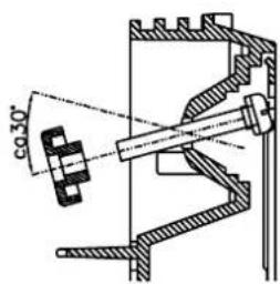
text_image
co 30°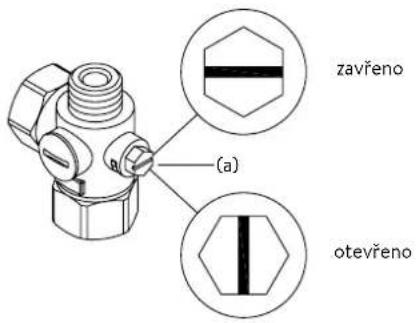
text_image
Diagram showing three steps of installing a digital display panel, labeled with arrows and numbered annotations.Obrázek B:
text_image
180mm 60mm 8mm

natural_image
Technical line drawing of an electrical enclosure with visible wiring and components (no text or labels)Multiple Power System MPS®:
text_image
Technical diagram showing a computer motherboard with labeled parts and a tool inserted, including numbered annotations 1, 2, and 3.text_image
Technical diagram of an electronic device with labeled components and internal wiring, showing exploded and assembled views.
flowchart
graph TD
    A["3"] --> B["2"]
    B --> C["1"]
    D["3"] --> E["2"]
    E --> F["1"]
    G["3"] --> H["2"]
    H --> I["1"]
Pol. VYP Pol. 1
Zamykací funkce
text_image
Technical diagram showing a mechanical component with an inset close-up of a textured surface, illustrating assembly or assembly process.https://partner.clage.com/en/service/device-registration/
Návod na použitie
natural_image
White industrial water heater with digital display showing 38-degree angle and control buttons (no text or symbols on main body)text_image
Main Menu Automatic User Statistics Savings Settings Info
text_image
Automatic Duration START < 1 min > Fill-Up START < 1001 > To define fill-up quantity see Statistics Consumption last tapping.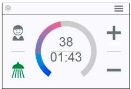
gauge
| Metric | Value | |--------|-------| | Current | 38 | | 01:43 | 38 |
text_image
42 90,0 Ltext_image
Temperature Limit Temperature Limit ON Max. Temperature < 53 > The Temperature Limit is set to 60°C at factory. Here you can limit the maximum outlet temperature of the appliance.text_image
Operation Lock Enter PIN > Protected Sections > Delete PIN >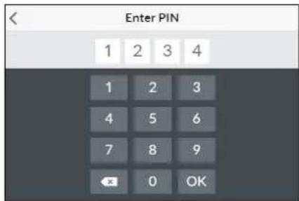
text_image
Enter PIN 1 2 3 4 1 2 3 4 5 6 7 8 9 OK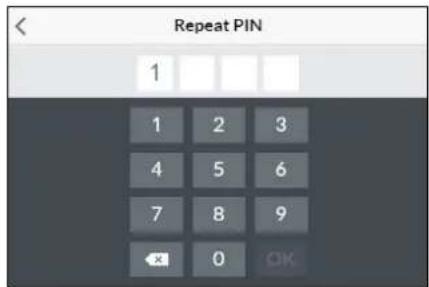
text_image
Repeat PIN 1 1 2 3 4 5 6 7 8 9 OK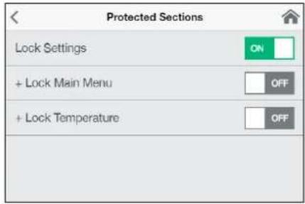
text_image
Protected Sections Lock Settings ON + Lock Main Menu OFF + Lock Temperature OFFtext_image
Brightness Operation < 70 > Standby < 5 >text_image
Device Information Power Consumption 0.0 kW Flow Rate 0 l/min Outlet Temperature 0.0 °C Inlet Temperature 0.0 °C Demand 0 kWInformácie »Info«
natural_image
Simple black-and-white line drawing of a cloud with two horizontal lines below (no text or symbols)Ako ušetrit'energiu
text_image
Diagram showing three steps of a door panel installation: opening, closing, and adding a temperature.Obrázok B:
text_image
Technical diagram showing a digital display panel connected to a wall-mounted panel with dimension annotations| Devices | |
| Searching Home Servers... | |
| Setup Home Server manually | > |
| Bluetooth Interface | > |
| Setup Assistant | > |
| Demo Mode | OFF |
B
| Devices | |
| No devices found. | |
| Setup Home Server manually | > |
| Bluetooth Interface | > |
| DFX_4521201101052108/16/2021 12:10:18 | + |
| DSX_06212049FFEE2208/16/2021 12:10:18 | + |
| Setup Assistant | > |
| Demo Mode | OFF |
| < | Connect Device |
| In order to connect to your device, please scan the QR Code on the device or enter the Bluetooth PIN manually. | |
| Scan QR Code > | |
| Enter PIN > |
| Advanced | |
| WLAN | ON |
| Operation Mode | Client > |
| The Home Server is connected to your existing WIFI-Network. | |
| Network | CLAGE_DE > |
| Password | |
text_image
Advanced WLAN ON Operation Mode Client > The Home Server is connected to your existing WIFI- Network. Network CLAGE_DE > Password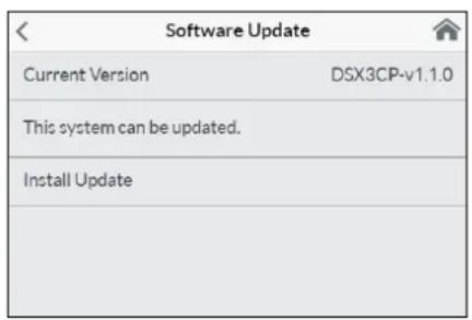
text_image
Software Update Current Version DSX3CP-v1.1.0 This system can be updated. Install Updatetext_image
Warning symbol with exclamation mark inside trianglenatural_image
3D CAD model of a mechanical housing or enclosure with internal grid structure and mounting holes (no text or symbols visible)Príslušenstvo k montáži
natural_image
Technical illustration of VDX pipe fittings and connectors (no text or symbols)natural_image
Product assembly of UDX connectors and wiring (no text or symbols visible)natural_image
Technical line drawing of a mechanical bracket assembly (no text or symbols)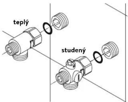
natural_image
Technical line drawing of an electronic device interior with circuitry and components (no text or symbols)Namontovanie zariadenia
natural_image
Technical line drawing of a mechanical bracket assembly with no visible text or symbols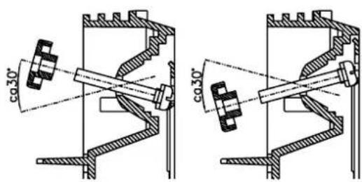
text_image
co.30° co.30°
text_image
uzavretý (a) otvorenýtext_image
Diagram showing three steps of installing a wall-mounted panel, with numbered annotations indicating component placement.Obrázok B:
text_image
Technical diagram showing a digital display panel connected to a wall-mounted panel with dimension annotationsnatural_image
Technical line drawing of a mechanical assembly with exploded and assembled views (no text or symbols)text_image
Technical diagram showing mechanical component assembly with magnified detail viewtext_image
180mm 60mm 8mm
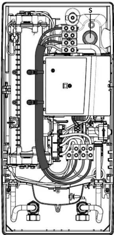
natural_image
Technical line drawing of an electrical enclosure with visible wiring and components (no text or labels)Multiple Power System MPS®:
text_image
Technical diagram showing a computer motherboard with labeled parts and a tool inserted, including numbered annotations 1, 2, and 3.text_image
Technical diagram of an electronic device with labeled components and internal wiring, showing exploded and assembled views.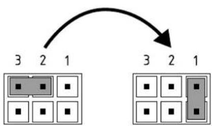
flowchart
graph TD
    A["3"] --> B["2"]
    B --> C["1"]
    D["3"] --> E["2"]
    E --> F["1"]
Poz. VYP Poz. 1
Blokovacia funkcia
text_image
(c)(b) Sito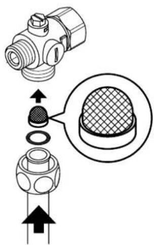
text_image
Technical diagram showing a mechanical component with cross-sectional view and directional arrows indicating assembly or assembly process.https://partner.clage.com/en/service/device-registration/
natural_image
White industrial water heater with digital display showing 38°C and control buttons (no text or symbols on main body)text_image
Main Menu Automatic User Statistics Savings Settings Info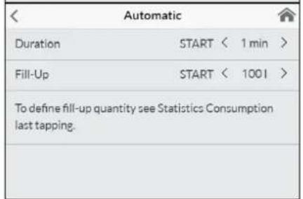
text_image
Automatic Duration START < 1 min > Fill-Up START < 1001 > To define fill-up quantity see Statistics Consumption last tapping.
gauge
| Metric | Value | |--------|-------| | Current | 38 | | 01:43 | 38 |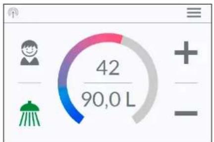
text_image
42 90,0 Ltext_image
Temperature Limit Temperature Limit ON Max. Temperature < 53 > The Temperature Limit is set to 60°C at factory. Here you can limit the maximum outlet temperature of the appliance.text_image
Operation Lock Enter PIN > Protected Sections > Delete PIN >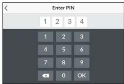
text_image
Enter PIN 1 2 3 4 1 2 3 4 5 6 7 8 9 OK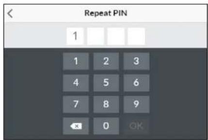
text_image
Repeat PIN 1 1 2 3 4 5 6 7 8 9 OK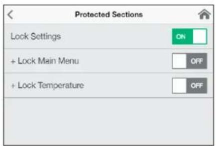
text_image
Protected Sections Lock Settings + Lock Main Menu + Lock Temperaturetext_image
Brightness Operation < 70 > Standby < 5 >text_image
Device Information Power Consumption 0.0 kW Flow Rate 0 l/min Outlet Temperature 0.0 °C Inlet Temperature 0.0 °C Demand 0 kWИнформация „Info“
natural_image
Simple black-and-white line drawing of a tree with two horizontal lines below (no text or symbols)text_image
Diagram showing three steps of a door panel installation with numbered instructions and a digital display.Фигура В:
Опционален монтаж с дюбели и винтове
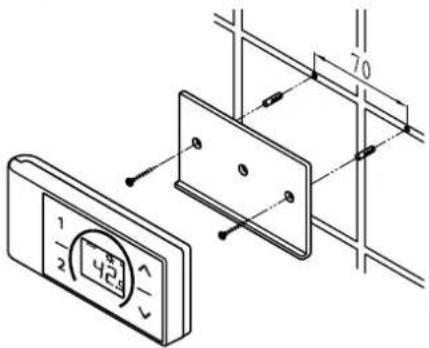
text_image
1 2 424 70| Devices | |
| Searching Home Servers... | |
| Setup Home Server manually | > |
| Bluetooth Interface | > |
| Setup Assistant | > |
| Demo Mode | OFF |
B
| Devices | |
| No devices found. | |
| Setup Home Server manually | > |
| Bluetooth Interface | > |
| DFX_4521201101052108/16/2021 12:10:18 | + |
| DSX_06212049FFEE2208/16/2021 12:10:18 | + |
| Setup Assistant | > |
| Demo Mode | OFF |
| < | Connect Device |
| In order to connect to your device, please scan the QR Code on the device or enter the Bluetooth PIN manually. | |
| Scan QR Code > | |
| Enter PIN > |
text_image
Advanced WLAN ON Operation Mode Client > The Home Server is connected to your existing WIFI- Network. Network CLAGE_DE > PasswordВръзка чрез WLAN
text_image
Advanced WLAN Operation Mode Client > The Home Server is connected to your existing WIFI- Network. Network CLAGE_DE > Passwordtext_image
Software Update Current Version DSX3CP-v1.1.0 This system can be updated. Install UpdateАктуализация на DSX Touch-софтуера
text_image
Warning symbol with exclamation mark inside trianglenatural_image
3D CAD model of a mechanical housing or enclosure with internal grid structure and mounting holes (no text or symbols visible)Монтажни аксесоари
natural_image
Product diagram of UDX cable connectors and connector parts (no text or symbols)Комплект тръби UDX
(Арт.№ 34110) – необходим е RDX / RDX 3!
natural_image
Technical line drawing of a mechanical bracket assembly (no text or symbols)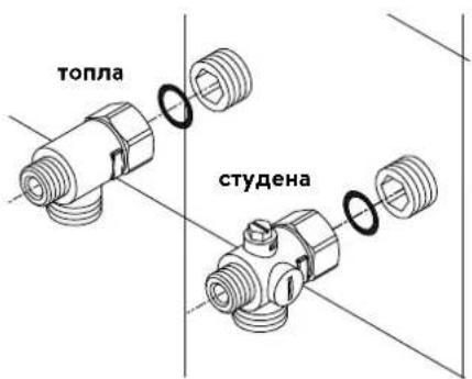
text_image
топла студенаnatural_image
Technical line drawing of an electronic device interior with circuitry and components (no text or symbols)Монтиране на уреда
natural_image
Technical line drawing of a mechanical bracket assembly (no text or symbols)
text_image
co 30°
text_image
φ30°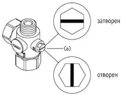
text_image
Diagram showing three steps of a device panel installation with numbered annotationsФигура В:
Опционален монтаж с дюбели и винтове

text_image
70 1/2 424natural_image
Technical line drawing of a mechanical assembly with exploded and assembled views (no text or symbols)text_image
Technical diagram showing mechanical component assembly with magnified detail viewtext_image
180mm 60mm 8mm
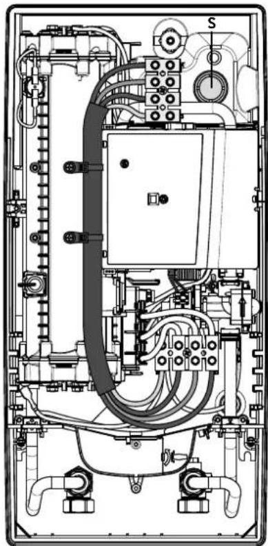
natural_image
Technical line drawing of an electrical enclosure with visible wiring and components (no text or labels)Multiple Power System MPS®:
text_image
Technical diagram showing a computer motherboard with labeled parts and a tool inserted, including numbered annotations.Повторно пускане в експлоатация
text_image
Technical diagram of an electronic device with labeled components and internal wiring, showing exploded and assembled views.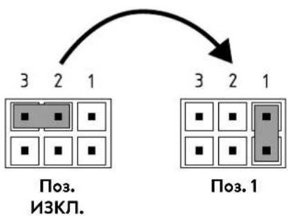
flowchart
graph TD
    A["3 2 1"] --> B["Поз. 1"]
    C["3 2 1"] --> D["Поз. 3"]
    style A fill:#ccc,stroke:#000
    style B fill:#ccc,stroke:#000
    style C fill:#ccc,stroke:#000
    style D fill:#ccc,stroke:#000
text_image
Technical diagram showing a mechanical component with an inset close-up of a textured surface, annotated with directional arrows and cross-sections.https://partner.clage.com/en/service/device-registration/
Uputstvo za upotrebu
Napomena: Priložene sigurnosne napomene pažljivo i potpuno pročitati pre instalacije, puštanja u rad i korišćenja kao i dalje postupanje, a poštovati i predviđenu namenu!
1. Opsi uređaja
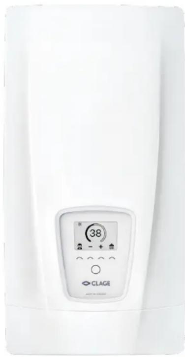
natural_image
White medical or laboratory device with a digital display showing 38 units and icons, no readable text or symbols beyond the label.E-komfort protočni bojler DSX Touch je u potpunosti elektronski kontrolisan protočni bojler sa Touch displejem i daljinskim upravljanjem za komforno i štedljivo napajanje vodom jedne ili više slavina.
Elektronika reguliše potrošnju energije u zavisnosti od odabrane izlazne temperature, postojeće ulazne temperature i količine protoka, kako bi u stepen precizno bila postignuta i konstantno održavana podešena temperatura čak i prikom oscilacija pritiska. Željena izlazna temepartura od 20 °C do 60 °C se unosi i očitava na displeju osetljivom na dodir. Alternativno se ovaj uređaj može kontrolisati preko Bluetooth ^® daljinskog upravljanja ili CLAGE aplikacije putem pametnog telefona ili tableta.
DSX Touch poseduje intuitivno kretanje kroz menije u kojima se mogu kreirati različiti korisnički profili i očitavati prikupljeni podaci.
Dovodna temperatura može da iznosi do 70 °C, tako da je moguć i režim rada za dogrevanje, npr. u solarnim sistemima.
Protočni bojler se može koristiti u kombinaciji sa eksternim relejem za rasterećenje za elektronski kontrolisane protočne bojlere (za detalje vidi uputstvo za montažu).
Čim otvorite ventil za toplu vodu na slavini, protočni bojler se automatski uključuje. Kada zatvorite slavinu uređaj se automatski isključuje. Rukovanje protočnim bojlerom se obavlja ili direktno na uređaju, preko daljinskog upravljanja ili pomoću CLAGE aplikacije putem pametnog telefona ili tableta.
CE
Pojednostavljena EU deklaracija o usaglašenosti
text_image
Two digital interface screenshots showing a shower gauge and a progress gauge with icons for cleaning, water, kitchen, and cooking.2. Upotreba
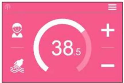
text_image
38.5
text_image
Main Menu Automatic User Statistics Savings Settings Info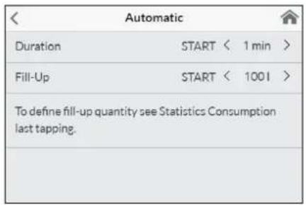
text_image
Automatic Duration START < 1 min > Fill-Up START < 1001 > To define fill-up quantity see Statistics Consumption last tapping.
text_image
38 01:43
text_image
42 90,0 LEco aktivan: Temperature primene i protok vode su ograničneni na energetski efikasne vrednosti. Simbol trepće ako preko podešavanja temperature bude podešena viša temperatura.
Održavanje: Dodirom na simbol otvara se statusna poruka sa dodatnim informacijama.
MAX Dostignuta maksimalna temperatura: Temperatura se ne može dalje povećavati jer je dostignuto ograničenje temperature. Ograničenje temperature se može menjati u galvnom meniju pod tačkom »Podešavanja«.
Modus istakanja
Kada se na nekoj slavini vrši istakanje zagrejane vode, glavni menja se komandni ekran u modusu istakanja i zavisno od podešene izlazne temperature menja boju pozadine od plave na niskim, do crvene na visokim temperaturama.
text_image
Temperature Limit Temperature Limit ON Max. Temperature < 53 > The Temperature Limit is set to 60°C at factory. Here you can limit the maximum outlet temperature of the appliance.Ograničenje temperature »Temperature Limit«: U ovom meniju može se aktivirati / deaktivirati ograničenje temperature i maksimalna izlazna temperatura dodirom na
text_image
Operation Lock Enter PIN > Protected Sections > Delete PIN >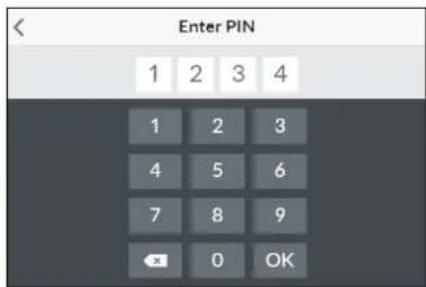
text_image
Enter PIN 1 2 3 4 1 2 3 4 5 6 7 8 9 OK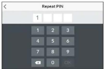
text_image
Repeat PIN 1 1 2 3 4 5 6 7 8 9 OK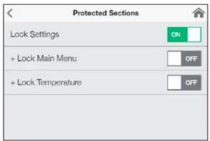
text_image
Protected Sections Lock Settings ON + Lock Main Menu OFF + Lock Temperature OFFtext_image
Brightness Operation < 70 > Standby < 5 >text_image
Device Information Power Consumption 0.0 kW Flow Rate 0 V/min Outlet Temperature 0.0 °C Inlet Temperature 0.0 °C Demand 0 kWInfo
Ovde se navode aktuelni podaci o statusu i podaci o uređaju. Prevlačenjem prsta prelistavate kroz različite vrednosti informacija.
Ograničenje snage
Kada puna snaga protočnog bojlera nije dovoljan da zagreje količnu vode koja se istače, servo ventil automatski ograničava količnu protoka tako da podešena zadata temperatura bude dostignuta.
Dogrevanje
Kod rada sa prethodno zagrejanom vodom (npr. solarnim sistemima) mora se osigurati da ulazna temperatura ne prelazi 70 °C.
Ukoliko u toku rada sa prethodno zagrejanom vodom ulazna temperatura prela- zi prethodno definisanu zadatu vrednost, ne dolazi do predaje snage. Na glavnom komandnom ekranu se prikazuje simbol 🌐.

natural_image
Simple black-and-white line drawing of a tree with two horizontal lines underneath (no text or symbols)text_image
Diagram showing three steps of a door panel installation with numbered instructions and a digital display.Slika B:
text_image
Technical diagram showing a digital display panel connected to a wall-mounted panel with dimension annotations| Devices | |
| Searching Home Servers... | |
| Setup Home Server manually | > |
| Bluetooth Interface | > |
| Setup Assistant | > |
| Demo Mode | OFF |
B
| Devices | |
| No devices found. | |
| Setup Home Server manually | > |
| Bluetooth Interface | > |
| DFX_4521201101052108/16/2021 12:10:18 | + |
| DSX_06212049FFEE2208/16/2021 12:10:18 | + |
| Setup Assistant | > |
| Demo Mode | OFF |
| < | Connect Device |
| In order to connect to your device, please scan the QR Code on the device or enter the Bluetooth PIN manually. | |
| Scan QR Code | > |
| Enter PIN | > |
| WLAN | ON | |
| Operation Mode | Client > | |
| The Home Server is connected to your existing WIFI-Network. | ||
| Network | CLAGE_DE | |
| Password | ||
Prvo puštanje u rad
Aplikacija Smart Control može se povezati sa DSX Touch putem Bluetooth-a ili WLAN mreže.
- Uverite se da protočni bojler ima strujno napajanje.
- Instalirajte upravljačku aplikaciju na vaš tablet / pametni telefon. U tom cilju u Apple AppStore ili Google Playstore potražite »CLAGE Smart Control« i instalirajte aplikaciju. Nemojte odmah da pokrenete upravljačku aplikaciju.
text_image
Advanced WLAN ON Operation Mode Client > The Home Server is connected to your existing WIFI- Network. Network CLAGE_DE > PasswordKonfiguracija kao Accesspoint
Kada DSX Touch želite da koristite kao samostalan Accesspoint, kreirajte individualnu i sigurnu lozinku, da uređaj zaštitite od neovlašćenog pristupa:
text_image
Warning symbol with exclamation mark inside trianglePopravke može da obavlja samo specijalizovani servis.
Ukoliko pomoću ove tabele ne možete da otklonite grešku uredaja, obratite se korisničkom servisu. Pripremite podatke sa tipske pločice uredaja!
Trimaran d.o.o.
Mihajla Pupina 17/3 smun
11185 Beograd
Srbija
Telefon: +381 11 4051 350
natural_image
3D mechanical assembly diagram showing internal components and mounting holes (no text or symbols)Pribor za montažu
Za instalacije u teškim uslovima ugradnje postoji pribor za montažu:
Okvir za montažu RDX 3
(art.br. 36100)
Pomoću okvira za montažu moguće je montirati protočni bojler kada električni priključak izlazi iz zida na bilo kom mestu ispod uređaja.
natural_image
Product assembly of UDX connectors and wiring (no text or symbols visible)Set cevi UDX
(art. br. 34110) - RDX / RDX 3 je neophodan! -
Pomoću ovog seta za montažu moguće je montirati protočni bojler kada se priključci za vodu završavaju iznad uređaja. Električni priključak može da izlazi iz zida na bilo kom mestu ispod uređaja, odn. da se nalazi na zidu.
5. Instalacija

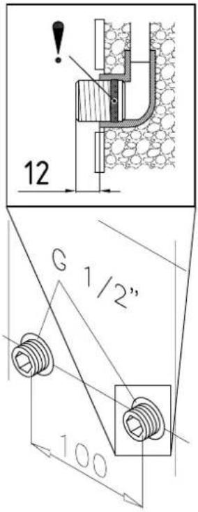
text_image
12 G 1/2" 100natural_image
Technical line drawing of a mechanical bracket assembly (no text or symbols)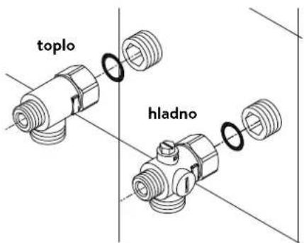
text_image
toplo hladnoInstalacija priključnih fitinga za vodu
Napomena: Umereno pritegnite obuhvatne navrtke da obezbedite zaptivanje bez oštećenja armatura ili cevi.
natural_image
Technical line drawing of an electronic device interior with circuitry and components (no text or symbols)Montaža uređaja
- Moguće je da se kabl za dovod struje nalazi u gornjem delu uredaja ili na zidu. U tom slučaju prvo pratite korake jedan do tri iz opisa »Električni priključak odozgo« iz poglavlja »Električni priključak«.
- Postavite uređaj na zidni držač tako da navojna šipka zidnog držača ulazi u za to predviđeni otvor na uređaju. Pažljivim savijanjem navojne šipke zidnog držača po potrebi možete da izvršite manje korekture. Priključne cevi za vodu uređaja moraju da se ušrafe bez primene sile.
- Zašrafite plastične nareckane navrtke na navojnu šipku zidnog držača.
- Zašrafite obe % colne obuhvatne navrtke priključnih cevi za vodu uređaja sa % colnom zapivkom na instalirane priključne fitinge.
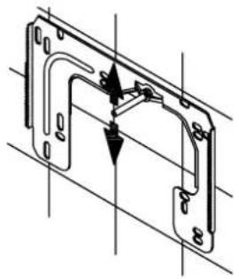
natural_image
Technical line drawing of a mechanical bracket assembly with no visible text or symbols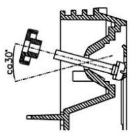
text_image
φ30°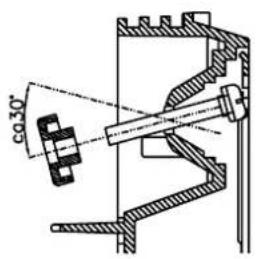
text_image
co 30°SR
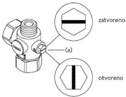
text_image
zatvoreno (a) otvoreno- Otvorite dovod vode i okrenite zaporni ventil (a) u priključnom fitingu hladne vode polako na (položaj »otvoreno«). Proverite sve spojeve na curenje.
- Zatim više puta otvorite i zatvorite odgovarajuću slavinu za toplu vodu sve dok iz cevi ne prestane da izlazi vazduh i dok protočni bojler ne bude odzračen.
5. Instalacija
Slika A:
text_image
Diagram showing three steps of installing a wall-mounted panel, with numbered annotations indicating component placement.Slika B:
text_image
Technical diagram showing a digital display panel mounted on a wall-mounted panel, with dimension annotations and control points.text_image
180mm 60mm 8mm
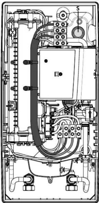
natural_image
Technical line drawing of an electrical enclosure with visible wiring and components (no text or labels)Električni priključak odozgo
Uverite se da je napajanje strujom isključeno pre povezivanja uređaja na električnu mrežu!
- Otvorite postojeće mesto za probijanje otvora na gornjem delu uređaja (S) po perforaciji snažnim pritiskom tupim alatom (npr. odvijačem). Kada je električni priključni kabl postavljen na zidu, dodatno otvorite otvor na desnoj strani donjeg dela uređaja.
- Isecite rukavac iz kesice sa priborom u skladu sa poprečnim presekom dovodnog kabla. Pri tom dimenzionirajte otvor rukavca nešto manje od poprečnog preseka priključnog kabla da bi ste postigli optimalnu zaštitu od vode. Prilagodite rukavac u skladu sa otvorom. Obavezno koristiti zaštitni rukvac!
- Skinite omotač priključnog kavla tako da rukavac ulazi u unutrašnjost uređaja. Uzimte pripremljeni uređaj u jednu ruku a drugom rukom provucite kabl kroz rukavac.
- Postavite uređaj na zidni držač, provucite navojnu šipku zidnog držača kroz za to predviđeni otvor na uredaju i fiksirajte uređaj.
- Čvrsto zašrafite priključnu klemu adapter kabla na gonjoj priključnoj tački. Sprovedite adapter kabl levo pored naponskog dela i pričvrstite oba držača na blok grejača.
- Otvorite preklopni držač. Povežite drugi kraj adapter kabla u skladu sa šemom povezivanja na donju priključnu klemu. Vodite računa o rasporedu faza!
- Ogolite pojedinačne žice priključnog kabla i povežite ih na gornju priključnu klemu u skladu sa elektro šemom. Povežite uređaj na zaštitni provodnik.
- Preklopite unazad preklopni držač i uklopite ga.
- Postavite haubu na uređaj i ušrafite zavrtanj za pričvršćivanje. Zatim možete da navučete masku odozdo do graničnika.
Multiple Power System MPS®:
Nazivna snaga (maks. primljena snaga) iznosi 27 kW pri 400 V i može se interno promeniti na 24 kW, 21 kW ili 18 kW!

text_image
Technical diagram showing a computer motherboard with labeled components and a tool inserted, including parts numbered 1, 2, and 3.Pre električnog povezivanja napunite vodom vodovodnu mrežu i uređaj kroz laganih otvaranja i zatvaranja slavine za toplu vodu i time je potpuno odzračite.
U tom cilju izvadite event. postavljene regulatore mlaza (perlatore) iz armature da bi ste obezbedili maksimalan protok. Isperite instalaciju tople i hladne vode u trajanju od najmanje jednog minuta.
Uređaj je potrebno ponovo odzračiti posle svakog pražnjenja (npr. posle radova na vodovodnoj instalaciji, zbog opasnosti od smrzavanja ili posle popravke uredaja) i pre ponovnog puštanja u rad.
Ukoliko se protočni bojler ne može pustiti u rad, proverite da li su se usled transporta aktivirali sigurnosni limitator temperature (STB) ili sigurnosni presostat (SDB). Uverite se da li je uređaj pod naponom i po potrebi resetujte sigurnosti prekidač.
Promena snage
Ovo može da obavlja samo ovlašćeno stručno lice, u suprotnom dolazi do gašenja garancije!
Prilikom prvog uključivanja naponskog napajanja mora biti podešena maksimalna snaga uređaja. Normalna funkcija uređaja je na raspolaganju tek nakon obavljenog podešavanja snage uređaja.
Maksimalna moguća snaga zavisi od instalacije. Obavezno poštujte podatke iz tabele »Tehnički podaci«, a posebno neophodan poprečni presek električnog priključnog kabla i osigurača. Dodatno poštujte propise standarda DIN VDE 0100.
- Uključite dovod struje ka uređaju.
- Prilikom prvog uključivanja naponskog napajanja na Touch komandnom panelu se nakon pribl. 40 sekundi prikazuje meni za izbor jezika. Odaberite željeni jezik. Sledi podešavanje snage. Ukoliko to nije slučaj sledite uputstva iz odeljka »Ponovno puštanje u red«.
- Preko Touch komandnog panela podesite maksimalnu snagu uređaja u zavisnosti od instalacije (18, 21, 24 ili 27 kW).
- Potvrdite podešavanje na »OK«.
- Obeležite podešenu snagu na tipskoj pločici.
- Nakon podešavanja maksimalne snage uređaja, grejanje vode se aktivira posle pribl. 10 – 30 sekundi kontinuiranog protoka vode.
- Otvorite ventil za ispuštanje tople vode. Proverite funkcionisanje protočnog bojlera.
- Ponovo pustite FX3 daljinski upravljač u rad u skladu sa koracima 2-6 u poglavlju »3. Daljinski upravljač« odeljak »Prijavljivanje daljinskog upravljača protočnog bojlera« (vidi stranu 338).
- Upoznajte korisnika sa upotrebom i predajte mu uputstvo za upotrebu.
- Popunite registracionu karticu i pošaljite je korisničkom servisu ili registrujte vaš uređaj online na našoj internet prezentaciji (vidi takođe i stranu 329).
text_image
(c)(b) CjediloRadove na održavanju može da obavlja samo ovlašćeni specijalizovani servis.