MCX 3 - Boiler Clage - Free user manual and instructions
Find the device manual for free MCX 3 Clage in PDF.
| Brand | Clage |
| Model | MCX 3 |
| Product type | Electric instantaneous water heater |
| Nominal capacity | 0.2 liter |
| Nominal power | 3.5 kW (220-240 V~) |
| Nominal current | 15 A |
| Nominal voltage | 1~ / N / PE 220-240 V AC |
| Adjustable temperature range | 35 °C, 38 °C and 45 °C |
| Factory-set outlet temperature | 38 °C |
| Factory-set flow rate (at 3 bar) | 2.0 l/min |
| Startup flow rate | 1.2 l/min |
| Shutdown flow rate | 1.0 l/min |
| Nominal pressure | 1 MPa (10 bar) |
| Weight (filled with water) | Approx. 1.5 kg |
| Dimensions (H × W × D) | 13.5 × 18.6 × 8.7 cm |
| Protection class | Class I |
| Protection degree | IP 25 |
| Heating system | Bare wires IES® |
| Required water resistivity (at 15 °C) | ≥ 1100 Ω·cm |
| Minimum cable cross-section | 1.5 mm² |
| Special features | Key lock, LED standby, service rinse |
| Supplied accessories | Special jet regulator CSP3, power cord with plug |
| Recommended maintenance | Cleaning with a damp cloth, no solvents |
Frequently Asked Questions - MCX 3 Clage
User questions about MCX 3 Clage
0 question about this device. Answer the ones you know or ask your own.
Ask a new question about this device
Download the instructions for your Boiler in PDF format for free! Find your manual MCX 3 - Clage and take your electronic device back in hand. On this page are published all the documents necessary for the use of your device. MCX 3 by Clage.
USER MANUAL MCX 3 Clage
E-mini instant water heater MCX3..7
de > 2
en > 18
fr > 34
nl > 51
pl > 67
cs > 84
pt > 100
Inhalt
DE
text_image
Warning symbol with exclamation mark inside triangleVor Installation
und Benutzung des
Gerätes lesen Sie
text_image
Technical diagram of an electronic device with numbered components for identificationnatural_image
White CLAGE water heater device with two connectors and a central control panel (no visible text or symbols on body)natural_image
Modern bathroom sink with faucet and wall-mounted sink (no visible text or symbols)4
natural_image
Modern bathroom sink with chrome faucet and wall-mounted sink (no visible text or symbols)natural_image
Technical line drawing of a mechanical assembly with screwdriver and tool (no text or symbols)6

text_image
Technical diagram showing a mechanical component with labeled parts 1, 2, and directional arrows indicating flow or movement.DE
text_image
① ~10° ② ~15° ③8. Elektroanschluss
natural_image
Technical diagram of two bolted components mounted on a base plate, with an arrow indicating direction (no text or symbols present)
natural_image
Technical diagram of a mechanical assembly with two cylindrical components mounted on a base plate, indicated by arrows (no text or symbols present)
natural_image
Technical diagram of a mechanical assembly with two flanged components and directional arrows indicating movement (no text or symbols)Abnehmen der Blende
natural_image
Technical line drawing of two bolted components mounted on a base plate (no text or symbols)
natural_image
Technical line drawing of a mechanical assembly with two flanged components and directional arrows (no text or symbols)natural_image
Technical line drawing of a mechanical assembly with rotating components and directional arrows (no text or symbols)13. Gebrauch
13
text_image
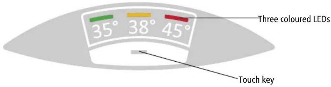
Drei farbige LEDs 35° 38° 45° Sensortaste- Overview ...... 19
- Description of appliance....20
- Technical specifications....21
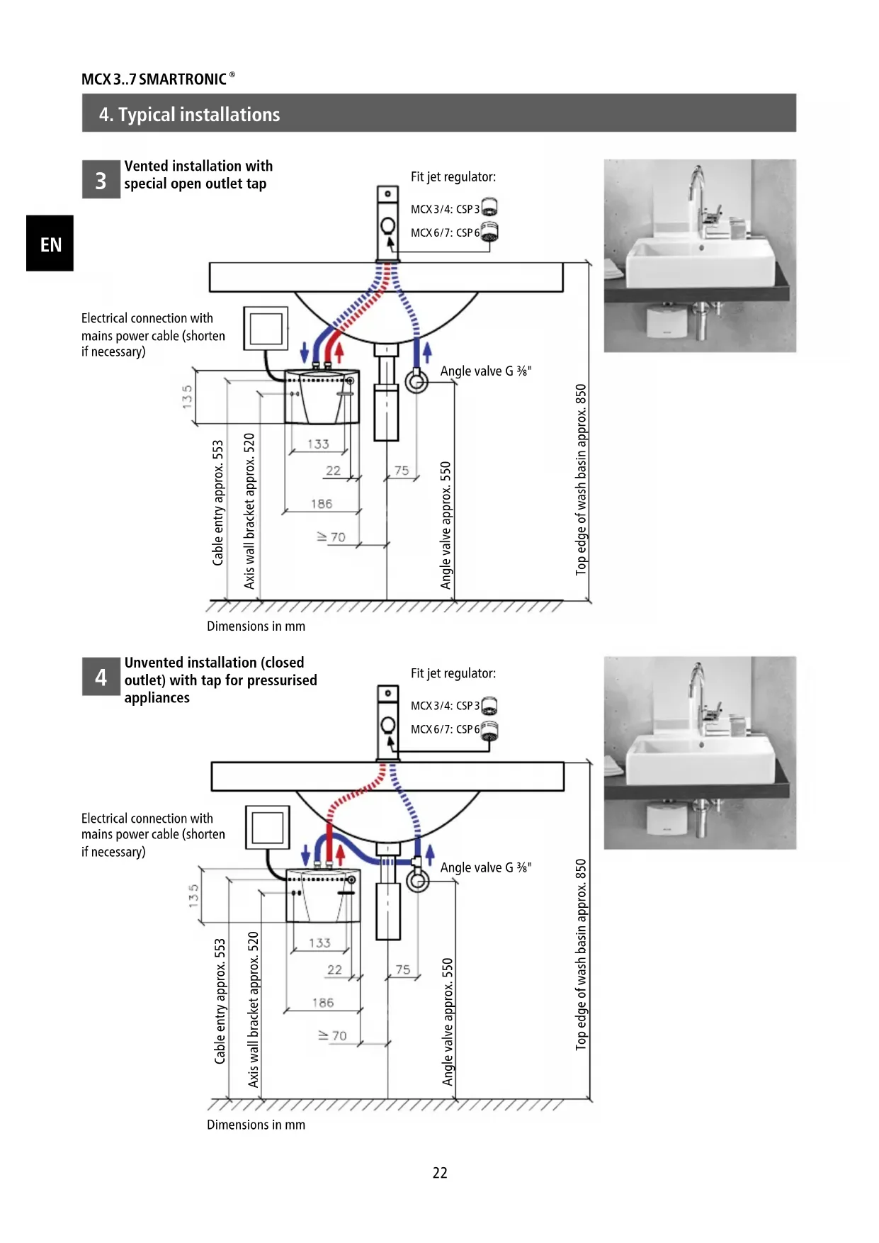
- Typical installations....22
Vented installation with special open outlet tap....22
Unvented installation (closed outlet) with tap for pressurised appliances....22
- The following must be observed....23
Shower application....23 - Flexible connecting hoses....24
- Installing the appliance ....25
Removing the appliance from the wall bracket 26
- Electrical connection....26
- Purging....27
- Commissioning ....27
- Rating plate cover....28
- Adjusting the water flow 29
- How to use....29
Temperature setting 29
- Deactivate / Activate LED-Standby 30
- Service flush function .... 30
Key lock and temperature lock....30
- Function overview....31
- Cleaning and Maintenance ....31
- Environment and Recycling ....31
- Troubleshooting and Service .... 32
- Product data sheet in accordance with EU regulation - 812/2013 814/2013....116

text_image
Warning symbol with exclamation mark inside triangleRead these operating instructions carefully before installing and using the heater!
Note: Carefully read the enclosed safety instructions through in full before the device is installed, put into service and used and follow them in the further steps and during use!
1. Overview
text_image
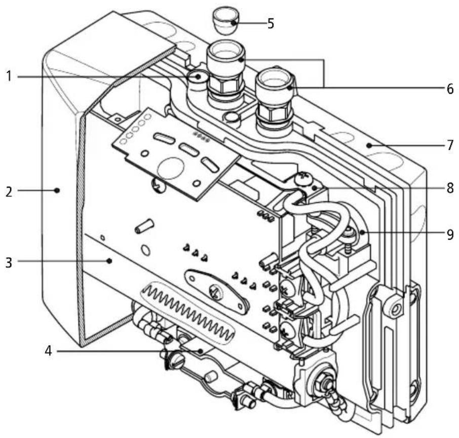
Technical diagram of an electronic device with numbered components for identification| Pos. | Description |
| 1 | Adjusting screw for water flow rate |
| 2 | Hood with control panel |
| 3 | Heating cartridge |
| 4 | Safety temperature limiter |
| 5 | Filter |
| 6 | Water connector |
| 7 | Wall bracket |
| 8 | Safety earthing terminal |
| 9 | Cable grommet |
EN
2. Description of appliance
EN
1
natural_image
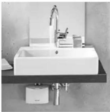
White CLAGE water heater device with two metallic fittings (no visible text or symbols on body)This instantaneous water heater (fig. 1) is intended to provide economical heating of water sufficient for a single outlet i.e. kitchen sink or wash basin and can be installed with a sanitary water fitting.
When the hot-water tap is opened, the heater switches itself on automatically when the minimum water flow rate is exceeded and heats the water as it passes through the appliance.
The heater is pre-set in the factory to an outlet temperature of about 38 °C, which is ideal for washing your hands. When this temperature is reached, the electronic regulator
reduces the power in order to ensure that the outlet temperature does not exceed this value. This automatic temperature regulation means that it is only necessary to open the hot water tap to obtain water at a constant, safe temperature for washing hands. On the control panel, the temperatures 35 °C , 38 °C and 45 °C can be selected. Cold water may be added if a lower temperature is required.
If the flow rate is too low, if the flow pressure is too low, or if the warm-water tap is closed, the appliance switches itself off automatically. For an optimum flow of water, always fit the special jet regulator enclosed with the appliance. This regulator is inserted into the thread on the end of the tap and fits into any standard sleeve size M 22/24.
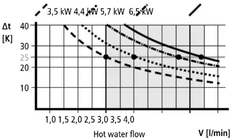
The maximum possible outlet temperature is determined by the temperature of the incoming water, the rate of flow and the heating power of the heater (see diagram). The flow rate can be pre-set ("Adjusting the water flow", 29).
2
max. temperature increase t_1-t_2 in Kelvin
line
| Hot water flow | V [l/min] | Δt [K] | | -------------- | --------- | ------ | | 1,0 | 1.0 | 40 | | 1,5 | 1.5 | 35 | | 2,0 | 2.0 | 30 | | 2,5 | 2.5 | 25 | | 3,0 | 3.0 | 20 | | 3,5 | 3.5 | 15 | | 4,0 | 4.0 | 10 |3. Technical specifications
| Typ | MCX 3 MC | CX 4 MCX 6 MC | CX 6-220 MC | CX 7 | |
| Art. No. | 15003 150 | 004 15006 15 | 005 15007 | ||
| Capacity Liter | 0,2 | ||||
| Nominal pressure MPa (bar) | 1 (10) | ||||
| Heating system | Bare wire heating system IES® | ||||
| Required water resistance at 15 °C in Ω cm | ≥ 1100 ≥ | 800 ≥ 800 ≥ | 800 ≥ 1100 | ||
| Electric supply | 1~ / N / PE 220 - 240 V AC | 1~ / N / PE 220V AC | 2~ / PE 400V AC | ||
| Nominal power rating | 3,5 kW 4,4 | kW 5,7 kW 6,0 | kW 6,5 kW | ||
| Nominal current | 15 A 19 A | 25 A 27 A 16 A | |||
| Temperature choice | 35 °C - 38 °C - 45 °C | ||||
| Factory temperature setting | 38 °C | ||||
| Maximum inlet temperature | 70 °C | ||||
| Factory flow setting at 3 bar | 2,0 l/min 2, | 5 l/min 3,3 l/min 4,5 l/min 3, | 7 l/min | ||
| Maximum temperature increase at rated power and a flow rate of...1) | 2,0 l/min 2,5 l/min 3,0 l/min 3,5 l/min 4,0 l/min | 25 K 31 K | 41 K 43 K 46 K | ||
| 20 K 25 K | 33 K 34 K 37 K | ||||
| 17 K 21 K | 27 K 29 K 31 K | ||||
| 14 K 18 K | 23 K 24 K 26 K | ||||
| 12 K 16 K | 20 K 21 K 23 K | ||||
| Required l/min to switch on l/min | 1,2 | 1,5 | 1,5 | 1,5 | 1,5 |
| Required l/min to switch off l/min | 1,0 | 1,3 | 1,3 | 1,3 | 1,3 |
| Min. required cable size 2) mm2 | 1,5 | 2,5 | 4,0 | 4,0 | 2,5 |
| Weight filled with water | ca. 1,5 kg | ||||
| Dimensions (H × W × D) | 13,5 × 18,6 × 8,7 cm | ||||
| Protection class acc. to VDE | 1 | ||||
| Type of protection according to VDE | IP 25 | ||||
1) Temperature rise (Kelvin) + cold-water temperature = maximum hot-water temperature ( ^ C) ≤ 70 ^ C
2) The cable size must not exceed 4 mm ^4
4. Typical installations
EN
3
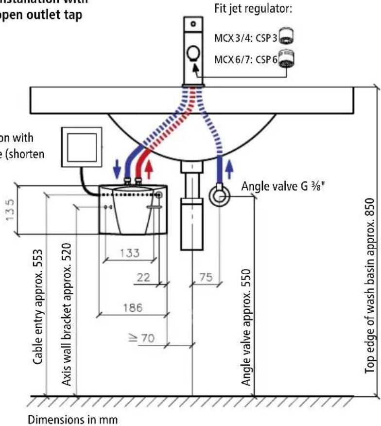
Vented installation with special open outlet tap
Electrical connection with mains power cable (shorten if necessary)
text_image
Installation with open outlet tap Fit jet regulator: MCX 3/4: CSP 3 MCX 6/7: CSP 6 on with (shorten 135 Cable entry approx. 553 Axis wall bracket approx. 520 133 22 186 ≥ 70 Angle valve G ¾" 75 Angle valve approx. 550 Top edge of wash basin approx. 850 Dimensions in mmFit jet regulator:
MCX 3/4: CSP 3
MCX6/7:CSP6
natural_image
Modern bathroom sink with faucet and wall-mounted sink (no visible text or symbols)4
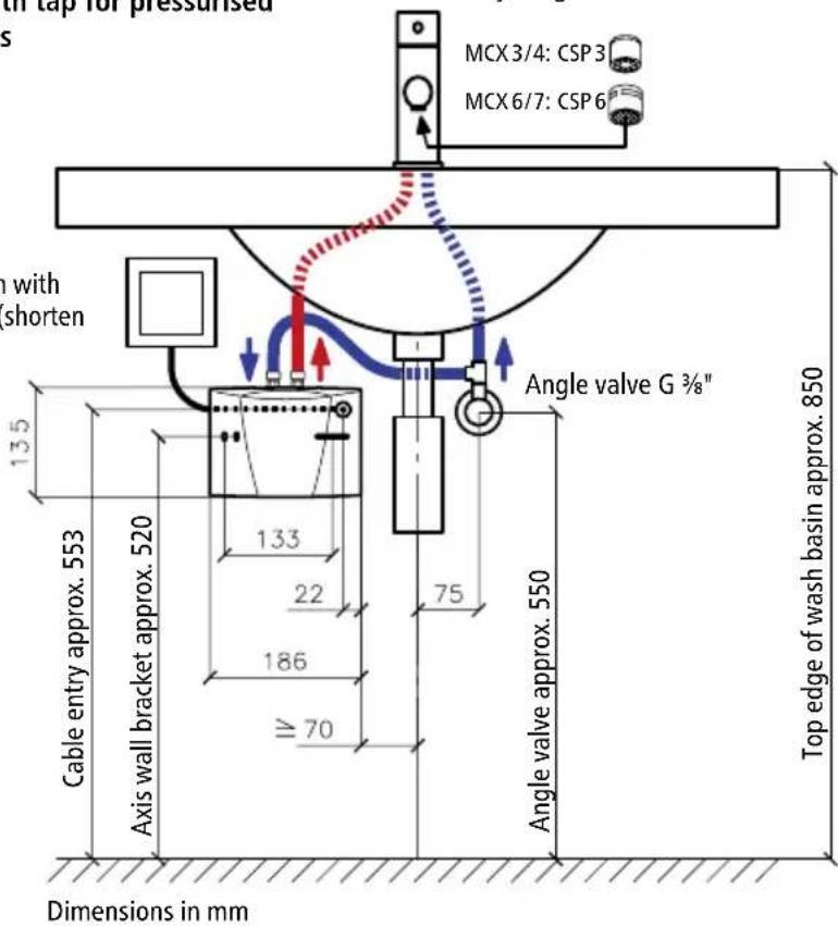
Unvented installation (closed outlet) with tap for pressurised appliances
Electrical connection with mains power cable (shorten if necessary)
text_image
with tap for pressurised s MCX 3/4: CSP 3 MCX 6/7: CSP 6 with shorten 13.5 133 22 186 70 Angle valve G 3/8" Cable entry approx. 553 Axis wall bracket approx. 520 75 Angle valve approx. 550 Top edge of wash basin approx. 850 Dimensions in mmFit jet regulator:
MCX 3/4: CSP 3
MCX 6/7: CSP 6

natural_image
Modern bathroom sink with chrome faucet and wall-mounted sink (no visible text or symbols)The heater is installed as shown in the immediate vicinity of the outlet in a frost-free room. We guarantee trouble-free operation only if CLAGE fittings and accessories are used. Note the following during installation:
- Installation must comply with DIN VDE 0100 and EN 806 and with the statutory regulations of the country and the provisions of the local electricity and water supply company.
- Check technical data and the information on the rating plate under the cover ("Removing the cover", 28).
- Ensure that all accessories are removed from the packing materials.
- Easy access to the appliance shall be guaranteed at all times. An external shut-off valve has to be installed.
- Thoroughly rinse the water pipes before connection.
- Optimum operation is ensured at a water flow pressure of 0.2 to 0.4 MPa (2–4 bar). The appliance must not be subjected to pressure exceeding 1 MPa (10 bar).
- For safe operation of this instantaneous water heater, a non return valve is not required. If, nevertheless, a non return valve has to be installed, it may only be placed in the hot water outlet line behind the instantaneous water heater.
- The water pipes must not exert any mechanical force on the water connections of the instantaneous water heater during installation and operation. If this cannot be guaranteed due to the installation conditions, we recommend the use of flexible connections.
- The minimum requirements for the required water resistance must be complied with. The required water resistance of the can be obtained from your water supply company.
Shower application
The hot water temperature may not exceed 55 °C if the appliance is connected to a shower. If the appliance is operated with preheated water, it must be ensured that its temperature is also limited to 55 °C by the customer.
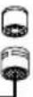
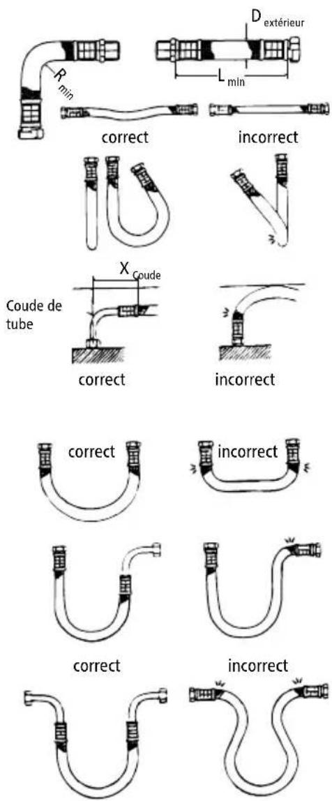
6. Flexible connecting hoses

text_image
Rmin D external Lmin correct wrong Xbend Pipe bend correct wrong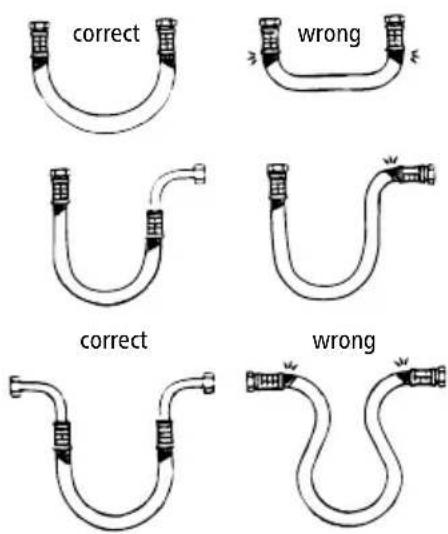
text_image
correct wrong correct wrongInstallation guidelines:
| Hose DN D | external | PN | R_min |
| 8 mm 12 | mm 20 bar 27 | mm |
Ensure sufficient equipotential bonding.
- The permissible bending radius R_min = 27 mm must be observed at all times, including during transport and assembly as well as when installed. If it is not possible to observe the minimum bending radius, a different installation method should be used or a suitable hose should be selected.
Please refer to the table for the minimum length:
| L_min | L_min = 90^ | L_min = 180^ L | _min = 360^ |
| 60 mm | 140 mm 180 mm | 260 mm |
- For curved installation there must be sufficient hose length available to form an open loop, as otherwise the hose will become kinked at the joints and thus destroyed.
- The hose length may change slightly due to the effects of pressure or heat. For straight installation, allowance should therefore be made to compensate for changes in the hose length.
- Never twist or kink the flexible connection.
- Ensure that the hose is never stressed by external tensile or compressive forces during assembly or when in use.
- Rigid connections (external thread) should not be further tightened after attaching the second connection, as this causes twisting and may damage the hose.
- The hose installer is always responsible for ensuring a tight join.
- The installer should check any sealing material supplied with the hose to ensure that it is suitable, as the hose manufacturer does not know the connection material or geometry.
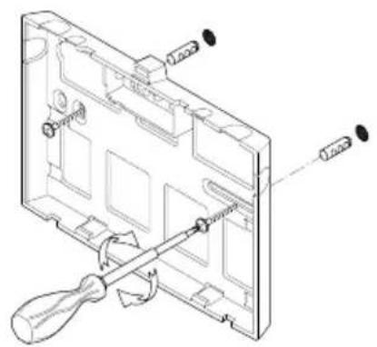
7. Installing the appliance
5
natural_image
Technical line drawing of a mechanical assembly with screwdriver and screwdriver (no text or symbols)6

text_image
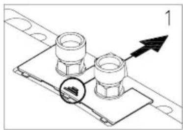
Technical diagram showing a mechanical component with labeled parts 1, 2, and directional arrows indicating flow or movement.• Install the appliance with the water connectors vertically upwards for direct connection to the sanitary tap.
- Secure the wall bracket to the wall with screws and suitable wall plugs (fig. 5).
- Place the appliance on the wall bracket and snap it into position (fig. 6). The appliance may only be operated, if it has been placed properly into the wall bracket!
- Tap connection (fig. 7): Cold water inlet (blue) and hot water outlet (red) are marked on the rating plate (under the rating plate cover).
- Connect the appropriate pipe or hose of the sanitary tap with the red-marked hot water outlet. Avoid exerting any kind of mechanical pressure on the appliance, e.g. by water pipes etc.
• After installation, carefully check all connections for leaks and rectify as necessary.
- In order to obtain an optimum water jet at low flow rates, always insert the enclosed jet regulator into the sleeve of the tap outlet. This insert fits commercially available sleeves with an M 22 or M 24 thread.
7
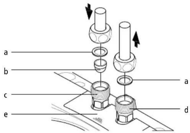
text_image
a b c e a da. Seal
b. Strainer
c. Cold water-connection (inlet)
d. Hot water-connection (outlet)
e. Rating plate cover
7. Installing the appliance
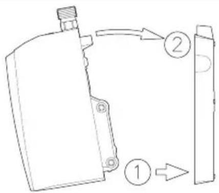
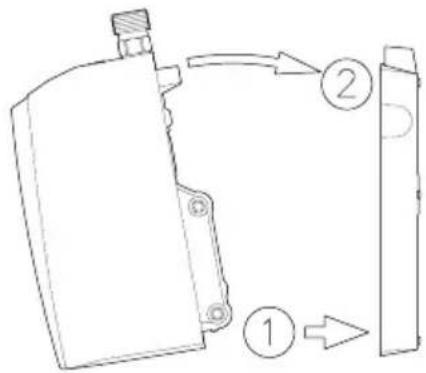
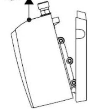
Removing the appliance from the wall bracket
Put the wide screwdriver tip into the interlock between the water connections until it stops, then press slightly upwards (1), tilt the appliance forward by max. 15^ (2) and remove it upwards (3).
8
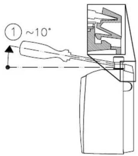
text_image
① ~10°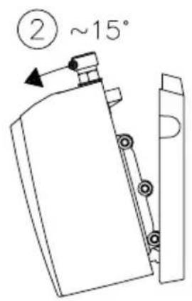
text_image
② ~15°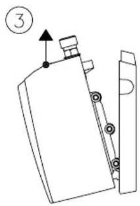
text_image
③8. Electrical connection
Only by a specialist!
Fill the appliance completely with water by repeatedly opening and closing the hot-water tap before connecting to electrical power. The heating element may be damaged if this is not done!
- Check that the power supply is switched off prior to electrical connection.
- The MCX 3 (3.5 kW) may be provided with a power cable and a protective earth plug by the factory. Please make sure that the feed cable, which leads to the protective earth plug socket, is dimensioned sufficient and that the socket is plugged to the conductor. The socket must be freely accessible. The power cable needs to be changed by the customer service department or an authorized electrician in case of defect, to avoid any danger.
- The mains cable of all other MCX models must be permanently connected via connecting box as shown in the circuit diagram (see fig. 9). The earth conductor must be connected.
- In accordance with IEC, a circuit breaker with a contact opening gap of at least 3 mm for each pole must be provided on the mains side of the connecting box.
- The wiring cross-section must be well adapted to the corresponding power rating.
- To protect the appliance, a fuse element must be fitted with a tripping current commensurate with the nominal current of the appliance.
8. Electrical connection
9
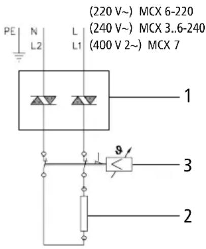
text_image
PE N L L1 (220 V~) MCX 6-220 (240 V~) MCX 3..6-240 (400 V 2~) MCX 7 1 3 2Circuit diagram
- Electronic regulator
- Heating element
- Safety thermal cut-out
9. Purging
To prevent damage to the appliance, the instantaneous water heater must be purged of air before using it for the first time.
Each time it is emptied (for example after work on the plumbing system or following repair work on the appliance), the instantaneous water heater must be purged before it is used again.
- Switch off the power supply to the instantaneous water heater.
- To purge the instantaneous water heater, open the hot water tap and wait until the water emerges free of air bubbles.
- Switch the power supply back on again.
10. Commissioning
Do not switch on the electric power at this time!
- Open the hot-water tap and allow water to flow until it emerges free of air bubbles.
- Now close the circuit breaker to connect the electrical supply. After a short power-up delay, the water heats up.
- Set the desired outlet temperature and adjust the water flow rate, if, for example, the temperature cannot be reached.
- Explain the functions of the heater to the user and ensure that he knows how to use it. Hand over these operating instructions to the user.
- Use the registration card for the registration at the factory service centre or register the appliance online on the website www.clage.com.
11. Rating plate cover
EN
10
natural_image
Technical diagram of two bolted components mounted on a base plate, with an arrow indicating direction (no text or symbols present)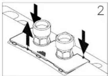
natural_image
Technical diagram of a mechanical assembly with two flanged components and directional arrows indicating motion (no text or symbols)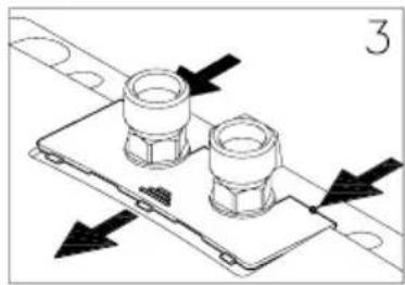
natural_image
Technical diagram of a mechanical assembly with two flanged components and directional arrows indicating movement (no text or symbols)Removing the cover
The rating plate and the hood screw are located under this cover.
- Push the cover at the corrugation towards the wall bracket.
- Press the cover down at the rear corners until the front edge lifts.
- Remove the cover by pulling forward.
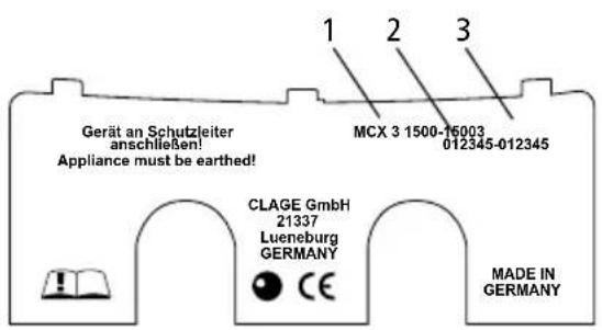
Rating plate cover
On the inner part of the cover, you can find the name of the application type (1), as well as the serial number (2) and the article number (3).
natural_image
Technical line drawing of two bolted components mounted on a base plate (no text or symbols)
natural_image
Technical diagram of a mechanical assembly with two bolted components and directional arrows (no text or symbols)Replacing the cover
- Push the cover flat towards the wall bracket under the edges of the water connections.
- Press down the front edge of the cover and push it forward again at the rear edge until it fits.
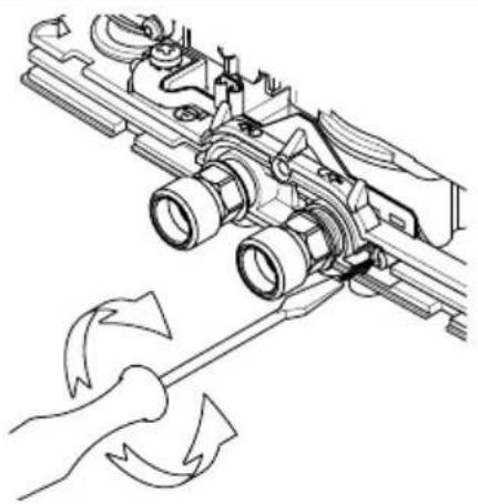
12. Adjusting the water flow
May only be carried out by a specialist.
Remove the cover (see Fig. 10), undo the hood screw underneath and remove the hood.
Decreasing the flow rate:
Turn the adjusting screw clockwise to decrease the flow rate, thus making a higher outlet temperature possible.
Increasing the flow rate:
Turn the adjusting screw counter-clockwise to increase the flow rate, thus reducing the possible outlet temperature.
12
| Direction Flow | Temperature increase |
natural_image
Technical line drawing of a mechanical assembly with tool and motion arrows indicating rotation (no text or symbols)13. How to use
13
text_image
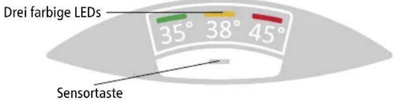
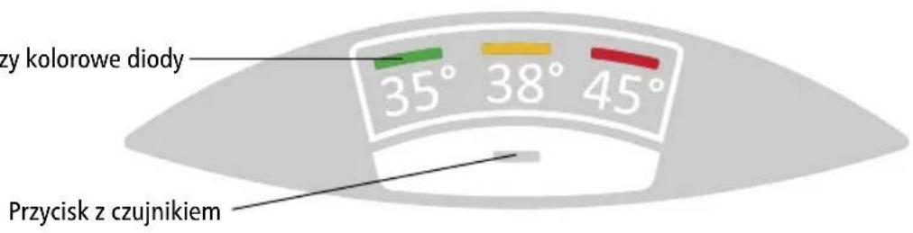
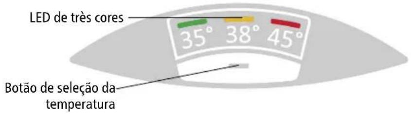
Three coloured LEDs 35° 38° 45° Touch keyTemperature setting
The touch key - allows you to select one of the three preset temperatures.
Every key press sets the temperature to the next level:
35^ C - 38^ C 45^ C (.)
Press the key once again starts the cycle all over.
The current selected temperature is indicated by one of three coloured LEDs.
13. How to use
Key lock and temperature lock
The current selected temperature setting can be locked against unintended alteration. Thus, the temperature cannot be changed by a single keypress anymore.
Activate keylock / Deactivate keylock:
Press and hold touch key for approx. 5 seconds until the active LED goes out, then release the touch key.
14. Deactivate / Activate LED-Standby
As an energy-saving function of the control panel, the active LED automatically goes out approx. 20 seconds after the last operation (e.g. tapping or temperature selection).
However, in order to be able to recognise the selected setting at any time, the LED can be permanently activated and the LED standby function deactivated with the following procedure:
- Press and hold the sensor button (approx. 7-8 seconds). After approx. 5 seconds, the active LED goes out. Continue to hold down the sensor key.
- The green and yellow LEDs light up to indicate activation/deactivation. Release the sensor key.
If the fitting is opened in LED standby mode (LED off) or the sensor key is pressed, the last active LED lights up (wake-up), but the temperature is not yet switched over. The temperature can only be adjusted when the button is pressed again.
The LED standby function can be reactivated in the same way.
This function remains stored even in the event of a power failure.
15. Service flush function
For the professional!
For thermal cleaning of the flexible hose and fitting, the outlet temperature can be set to ≥50 ^ for the next tapping. When the service rinse function is active, showering is not permitted due to the high temperatures.
- Press and hold the sensor button (approx. 10-12 seconds) until the red and yellow LEDs light up. Release the sensor key.
- Open the hot water valve on the fitting. To reach the maximum temperature, reduce the flow at the fitting or the angle valve until the red and yellow LEDs light up continuously.
- The function is deactivated as soon as another temperature is set or the flow falls below the minimum for 30 seconds (water stop).
16. Function overview
By operating with a single key, the unit runs through all special functions one after the other when the key is held down for a long time. The LEDs indicate the function that is activated or deactivated at the respective moment when the operating button is released.
| Keystroke LED indication Function | ||
| 0 – 3 seconds GREEN | → YELLOW → RED → GREEN... Temperature | change |
| 4 – 6 seconds OFF Key lock and temperature lock | ||
| 7 – 9 seconds GREEN | + YELLOW Deactivate / Activate LED-Standby | |
| 10 – 12 seconds YELLOW | + RET Service flush function activated | |
| ≥13 seconds Original | indication reappears Cancel entry | |
17. Cleaning and Maintenance
- The appliance and the fittings should only be cleaned with a damp cloth. Do not use abrasive or chlorine-based cleaning agents or solvents.
- Keep the control panel area dry!
- Clean the jet regulator or the hand-shower regularly and replace as necessary.
- Dirt and scale deposited in the pipes and heater will affect the function of the heater. Typical indications include reduced rate of flow or noisy flow. In such cases, have the heater inspected by a technician and, if necessary, have the filter in the cold-water inlet cleaned.
18. Environment and Recycling
This product was manufactured climate neutrally according to Scope 1 + 2. We recommend the purchase of 100% green electricity to make the operation climate neutral as well.
Disposal of transport and packaging material: For smooth transport your product is carefully packed. The disposal of the transport material is carried out by the specialist tradesman or the specialist trade. Separate the sales packaging according to materials separated according to materials via one of the dual systems in Germany.
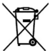
Disposal of old products: Your product was manufactured from high-quality, reusable materials and components. Products marked with the crossed-out wheeled bin symbol must be disposed of separately from household waste at the end of their service life. Therefore, take this product to us as the manufacturer or to one of the municipal collection points that recycle used electronic devices. This proper disposal serves to protect the environment and prevents possible harmful effects on humans and the environment that could result from improper handling of the products at the end of their service life.
18. Environment and Recycling
For more detailed information on disposal, please contact your nearest collection point or recycling centre or your local council.
Business customers: If you wish to discard equipment, please contact your dealer or supplier for further information.
For disposal outside Germany, please also observe the local regulations and laws.
19. Troubleshooting and Service
The following table will help you to determine and rectify the reasons for possible problems.
| Fault Cause Action | ||
| No water flows Water | supply is turned off | Open the main water valve and the shut-off valve |
| Water flows more slowly than expected | The jet regulator is not fitted | Fit the special CLAGE jet regulator |
| Water pressure is not sufficient | Check the water flow pressure or let check the water flow adjustment by an authorized technician | |
| Dirt in the pipes | Remove any dirt from the filter, valves and taps / check the technical data | |
| The heater switches itself on and off | Water pressure is varying, flow rate is too low | Remove any dirt / increase the flow water pressure, close other taps, open the shut-off valve further |
| Water remains cold | Water pressure is not sufficient | Let adjust the water flow by an authorized technician, open the shut-off valve, fit the special CLAGE jet regulator, check water pressure |
| Dirt Remove dirt from the inlet and outlet | ||
| Hot water temperature varies | Supply voltage varies Check the supply voltage | |
| Water connections mixed up Check installation | ||
| Hot water temperature too low and one LED flashes slowly | Flow rate is too high or inlet temperature is too low | Adjust the flow either at the tap, the valve or have the flow adjusted by a authorized technician ("Adjusting the water flow", 29). |
| One LED flashes rapidly and water remains cold | Defective temperature sensor | Replace temperature sensor (authorized technician) |
| Defective heating element | Replace heating element (authorized technician) | |
19. Troubleshooting and Service
| All LEDs flash rapidly and water gets warm | Defective control panel cable | Reposition control panel connector (authorized technician) |
| Replace control panel (authorized technician) | ||
| All LEDs flash rapidly and water remains cold | Defective power unit Call customer service | |
| LED turns off shortly after keypress | Keylock is active Deactivate keylock ("How to use", 30) | |
| LED flashes after keypress | Touch key was not touched in centre | Don’t touch the touch key for approx. 3 seconds (until LED lights up normally); for proper handling, touch the touch key right in the centre |
| Touch key calibration active | ||
| No LED lights LED Standby active | Check LED by touching the touchkey. If still no LED lights up, check the fuses! | |
If the connection cable is damaged, it must be replaced with an original spare cable from the manufacturer by an authorised technician in order to avoid any hazards.
If you cannot rectify the fault with the aid of the troubleshooting table, please contact customer service.
CLAGE GmbH
After-Sales Service
Pirolweg 4
21337 Lüneburg
Germany
Phone: +49 4131 8901-400
Email: service@clage.de
We can either give you the name and address of an authorised customer service company or repair the heater ourselves. In the latter case, please send in the heater (at your cost and risk) with details of the problem and a copy of the sales invoice.
Sommaire
text_image
Technical diagram of an electronic device with numbered components for identificationnatural_image
White CLAGE water heater device with two ports and a label '1' in corner (no readable text on body)natural_image
Modern bathroom sink with faucet and wall-mounted sink (no visible text or symbols)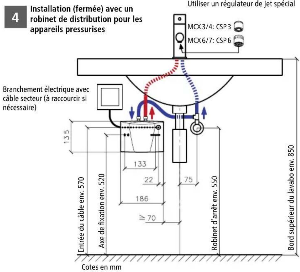
natural_image
Modern bathroom sink with chrome faucet and wall-mounted sink (no text or symbols visible)6. Tuyaux de raccordement souples

text_image
Rmin Dextérieur Lmin correct incorrect XCoude Coude de tube correct incorrect correct incorrect correct incorrect correct incorrectnatural_image
Technical line drawing of a mechanical assembly with screwdriver and tool (no text or symbols)6
text_image
Technical diagram showing a mechanical component with labeled parts 1, 2, and directional arrows indicating flow or movement.FR
natural_image
Technical diagram of two bolted components mounted on a metal plate with mounting holes (no text or symbols)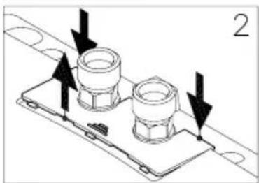
natural_image
Technical line drawing of a mechanical component with two flanged parts and directional arrows indicating movement (no text or symbols)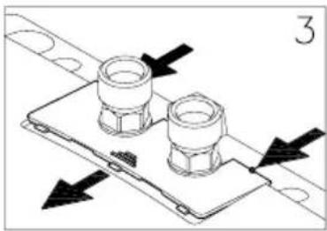
natural_image
Technical diagram of a mechanical assembly with two flanged components and directional arrows indicating movement (no text or symbols)Dépose du cache
natural_image
Technical line drawing of two bolted components mounted on a base plate (no text or symbols)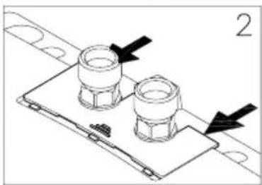
natural_image
Technical diagram of a mechanical assembly with two bolted components and directional arrows (no text or symbols)Pose du cache
text_image
Technical diagram of an electronic device with numbered components for identificationnatural_image
White CLAGE water heater device with two top ports and a base (no visible text or symbols on body)natural_image
Modern bathroom sink with faucet and wall-mounted sink (no visible text or symbols)NL
natural_image
Modern bathroom sink with chrome faucet and wall-mounted sink (no visible text or symbols)natural_image
Technical line drawing of a device's internal components with screwdriver and screwdriver (no text or symbols)6
text_image
Technical diagram showing a mechanical component with labeled parts 1, 2, and directional arrows indicating flow or movement.natural_image
Technical diagram of two bolted components mounted on a base plate, with an arrow indicating direction (no text or symbols present)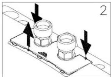
natural_image
Technical diagram of a mechanical component with two bolts and directional arrows indicating assembly or movement (no text or symbols)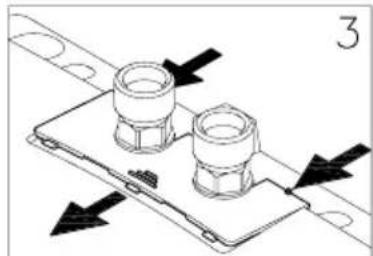
natural_image
Technical diagram of a mechanical assembly with two flanged components and directional arrows indicating movement (no text or symbols)natural_image
Technical line drawing of two bolted components mounted on a base plate (no text or symbols)
natural_image
Technical line drawing of a mechanical component with two bolts and mounting holes (no text or symbols)text_image
Warning symbol with exclamation mark inside triangletext_image
Technical diagram of an electronic device with numbered components for identificationnatural_image
White CLAGE water heater device with two connectors and a central display (no visible text or symbols on body)natural_image
Modern bathroom sink with faucet and wall-mounted sink (no text or symbols visible)PL
4
natural_image
Modern bathroom sink with chrome faucet and wall-mounted sink (no text or symbols visible)natural_image
Technical line drawing of a device's internal components with screwdriver and screwdriver (no text or symbols)6

text_image
Technical diagram showing a mechanical component with labeled parts 1, 2, and directional arrows indicating flow or movement.PL
natural_image
Technical line drawing of a mechanical component with mounting holes and a directional arrow (no text or symbols)③
natural_image
Technical line drawing of a mechanical component with mounting holes and a side view (no text or symbols)natural_image
Technical diagram of two bolted components mounted on a base plate, with an arrow indicating direction (no text or symbols present)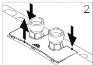
natural_image
Technical diagram of a mechanical assembly with two flanged components and directional arrows indicating movement (no text or symbols)
natural_image
Technical diagram of a mechanical assembly with two flanged components and directional arrows indicating movement (no text or symbols)Zdejmowanieosłony
natural_image
Technical line drawing of a mechanical component with two flanged parts mounted on a base plate (no text or symbols)
natural_image
Technical line drawing of a mechanical assembly with two flanged components and directional arrows indicating movement (no text or symbols)Zakładanie ostony
natural_image
Technical line drawing of a mechanical assembly with a hand holding a tool, showing no text or symbols.13.Eksploatacja
13
Trzy kolorowe diody
text_image
Warning symbol with exclamation mark inside triangletext_image
Technical diagram of an electronic device with numbered components for identificationnatural_image
White CLAGE water heater device with two connectors and a central top (no visible text or symbols on body)natural_image
Modern bathroom sink with faucet and wall-mounted sink (no visible text or symbols)4
natural_image
Modern bathroom sink with chrome faucet and stainless steel floor (no text or symbols visible)natural_image
Technical line drawing of a mechanical assembly with screwdriver and tool (no text or symbols)6

text_image
Technical diagram showing a mechanical component with labeled parts 1, 2, and directional arrows indicating flow or movement.text_image
8 ① ~10° ② ~15° ③ CSnatural_image
Technical diagram of two bolted components mounted on a base plate, with an arrow indicating direction (no text or symbols present)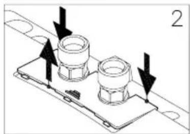
natural_image
Technical diagram of a mechanical assembly with two flanged components and directional arrows indicating motion (no text or symbols)
natural_image
Technical diagram showing two bolted components mounted on a base plate with directional arrows indicating movement (no text or symbols)Demontážkrytu
natural_image
Technical line drawing of a mechanical component with two bolts and a base plate (no text or symbols)
natural_image
Technical diagram of a mechanical assembly with two bolted components and directional arrows (no text or symbols)Nasazení krytu
natural_image
Technical line drawing of a mechanical assembly with rotating components and a hand holding a tool (no text or symbols)CS
13. Použití
13
text_image
Warning symbol with exclamation mark inside triangletext_image
Technical diagram of an electronic device with numbered components for identificationnatural_image
White CLAGE water heater device with two connectors and a central display (no visible text or symbols on body)natural_image
Modern bathroom sink with faucet and bathtub (no visible text or symbols)PT
4
natural_image
Modern bathroom sink with chrome faucet and wall-mounted sink (no text or symbols visible)natural_image
Technical line drawing of a mechanical assembly with screwdriver and tool (no text or symbols)6

text_image
Technical diagram showing a mechanical component with labeled parts 1, 2, and directional arrows indicating flow or movement.text_image
① ~10° ② ~15° ③natural_image
Technical diagram of two bolted components mounted on a base plate, with an arrow indicating direction (no text or symbols present)
natural_image
Technical diagram of a mechanical assembly with two flanged components and directional arrows indicating motion (no text or symbols)
natural_image
Technical diagram of a mechanical assembly with two flanged components and directional arrows indicating movement (no text or symbols)Remoçãodaprotecção
natural_image
Technical line drawing of a mechanical component with two bolts and a base plate (no text or symbols)
natural_image
Technical diagram of a mechanical assembly with two flanged components and directional arrows (no text or symbols)Colocação da tampa
natural_image
Technical line drawing of a mechanical assembly with rotating components and directional arrows (no text or symbols)PT
13. Utilização
13
> en Product data sheet in accordance with EU regulation
(a) Brand name or trademark, (b.1) Model, (b.2) Type, (c) Specified load profile, (d) Energy-efficiency class, (e) Energy-efficiency, (f) Annual power consumption, (g) Additional load profile, the appropriate energy-efficiency and the annual power consumption, if applicable, (h) Temperature setting for the temperature controller, (i) Sound power level, internal.
Additional notes: All specific precautions for assembly, installation, maintenance and use are described in the operating and installation instructions. All data in this product data sheet are determined by applying the specifications of the relevant European directives. Differences to other product information listed elsewhere may result in different test conditions. The power consumption was determined in compliance with standardized measurement method based on EU guidelines. The real energy consumption is pending on individual requirements.