M3 - Boiler Clage - Free user manual and instructions
Find the device manual for free M3 Clage in PDF.
User questions about M3 Clage
0 question about this device. Answer the ones you know or ask your own.
Ask a new question about this device
Download the instructions for your Boiler in PDF format for free! Find your manual M3 - Clage and take your electronic device back in hand. On this page are published all the documents necessary for the use of your device. M3 by Clage.
USER MANUAL M3 Clage
natural_image
White CLAGE device with black connectors and a small logo on top (no visible text or symbols on body)E-mini instant water heater M 3..7

natural_image
Simple line icons showing a hand pointing upward, a hand gesture with wrench, and a document with lines (no text or symbols)de > 2
en > 16
fr > 30
nl > 44
pl > 59
cs > 73
sk > 87
no > 101
sv > 115
bg > 129
fi > 143
pt > 157
es > 171
Inhaltsverzeichnis
DE
natural_image
Technical line drawing of a mechanical assembly with screwdriver and adjustment parts (no text or symbols)
text_image
Technical diagram showing a mechanical component with labeled parts 1, 2, and directional arrows indicating flow or movement.M 3, M 4 (230 V) M 6 (230 V)
text_image
PE N L Q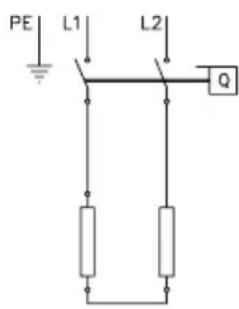
text_image
PE L1 L2 Qnatural_image
Diagram showing four mechanical components with an arrow indicating direction (no text or symbols)natural_image
Technical diagram of a mechanical assembly with two cylindrical components and an arrow indicating direction (no text or symbols)
natural_image
Technical diagram showing two mechanical components mounted on a base plate with directional arrows indicating assembly or movement (no text or symbols present)
natural_image
Technical diagram of a mechanical assembly with two cylindrical components mounted on a base plate, showing directional arrows (no text or symbols)natural_image
Technical line drawing of a mechanical assembly with cylindrical components and threaded ends (no text or symbols)text_image
① ~10° ② ~15° ③1. Description of appliance
1.1 Technical specifications ..... 17
1.2 Recommended open-outlet taps ..... 17
1.3 Dimensions.... 18
1.4 Scope of delivery 18
2. Installation
2.1 Typical installation: vented (open) installation....19
2.2 Installation instructions....20
2.3 Water connection....20
2.4 Electrical connection ..... 21
2.5 Initial start-up.....23
3. Use
3.1 Rating plate cover 24
3.1.1 Removing the cover ..... 24
3.2 Adjusting the water flow and temperature.....25
3.3 Changing the strainer ..... 26
3.4 Purging 26
3.5 Cleaning and maintenance.....26
4. Troubleshooting
4.1 Self-help when problems occur.....27
4.3 Spare parts ..... 28
4.2 Customer service address ..... 28
5. Disposal
5.1 Disassembly 29
5.2 Environment and recycling ..... 29
6. Product data sheet in accordance with EU regulation 812/2013 814/2013
(Is attached at the end of this document)
Note: Carefully read the enclosed safety instructions through in full before the appliance is installed, put into service and used and follow them in the further steps and during use!
Description of appliance
1. Description of appliance
This instantaneous water heater is intended to provide the economical heating of water sufficient for a single outlet, i.e. handwash basin, and must be connected to a special open-outlet tap to avoid any overpressure.
When the hot water tap is opened, the instantaneous water heater switches itself on automatically and heats the water as it passes through the appliance. It is only then that the appliance uses electricity. The temperature increase depends on the flow rate.
1.1 Technical specifications
| Type M 3 M 4 M 6 M 7 | ||||
| Energy efficiency class A | *) | |||
| Capacity Litre | 0.2 | |||
| Max. operating pressure MPa (bar) 0 (0); Open outlet only! | ||||
| Heating system Bare wire heating system IES | ® | |||
| Min. water resistance at 15 °C1) Ωcm | 1100 | |||
| Max. water inlet temperature °C 20 | ||||
| Rated voltage 1~ / N / PE 230 V AC 2~ / PE 400 V AC | ||||
| Rated power kW | 3.5 | 4.4 | 5.7 | 6.5 |
| Rated current A | 15.2 | 19.1 | 24.8 | 16.3 |
| Required min. cable cross-section mm2 | 1.5 | 2.5 | 4.0 | 1.5 |
| Hot water output at Δt = 25 K2) l/min | 2.0 | 2.5 | 3.3 | 3.7 |
| Switching on at l/min | 1.3 | 1.8 | 2.2 | 2.4 |
| Switching off at l/min | 1.0 | 1.4 | 1.7 | 2.0 |
| Approx. weight when filled with water kg | 1.5 | |||
| Protection class | IP 25 | |||
| Marking / Approvals | see rating plate | |||
*) The declaration complies with the EU regulation No 812/2013. The product data sheet is attached at the end of this document.
1) The specific resistance can be asked for at your water distribution company.
2) Temperature increase from e.g. 15 °C to 40 °C.
1.2 Recommended open-outlet taps
| Type | SNM | END | EWT | AEN |
| Art. No. | 1100-04200 | 1100-04410 | 1100-04420 | 1100-04255 |
 | 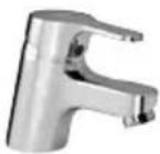 | 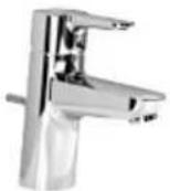 |  |
Description of appliance
1.3 Dimensions

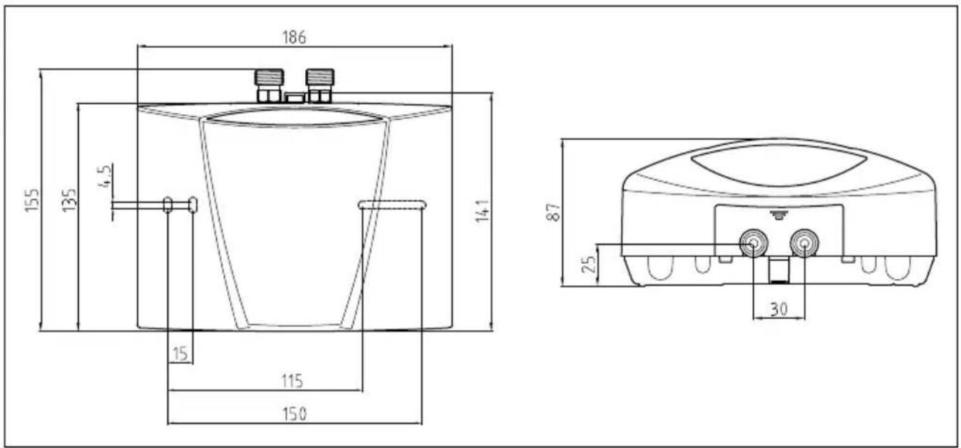
text_image
186 155 135 4,5 14,1 15 115 150 87 25 30Fig. 1: "Dimensions" (in mm)
1.4 Scope of delivery
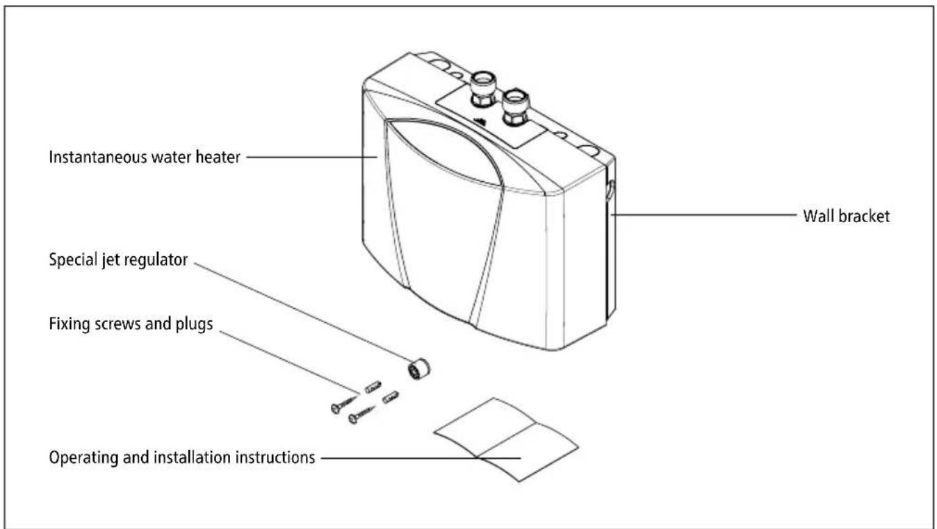
text_image
Instantaneous water heater Wall bracket Special jet regulator Fixing screws and plugs Operating and installation instructionsFig. 2: "Scope of delivery"
Installation
2. Installation
⚠️ Installation, initial operation and maintenance of this appliance must only be conducted by an authorised professional, who will then be responsible for adherence to applicable standards and installation regulations. We assume no liability for any damages caused by failure to observe these instructions!
2.1 Typical installation: vented (open) installation
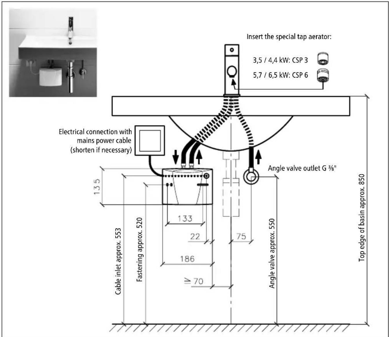
text_image
Insert the special tap aerator: 3,5 / 4,4 kW: CSP 3 5,7 / 6,5 kW: CSP 6 Electrical connection with mains power cable (shorten if necessary) 13.5 133 22 186 ≥70 Cable inlet approx. 553 Fastening approx. 520 Angle valve outlet G ¾" 75 Angle valve approx. 550 Top edge of basin approx. 850Fig. 3: "Vented installation with a special open-outlet tap" (dimensions in mm)
Installation
2.2 Installation instructions
The heater is installed directly to the connecting pipes of the tap. We guarantee trouble-free operation of the instantaneous water heater only if CLAGE fittings and accessories are used. Note the following during installation:
- Installation must comply with DIN VDE 0100 and EN 806 and with the statutory regulations of the country and the provisions of the local electricity and water supply company.
- Check the technical data and information on the rating plate.
- Easy access to the instantaneous water heater must be guaranteed at all times for maintenance purposes. An separate shut-off valve must be installed.
- Only use the appliance with an open-outlet tap.
- Ensure that all accessories are removed from the packaging.
- The minimum requirements for the required water resistance must be complied with. The required water resistance of the can be obtained from your water supply company.
- This appliance is not suitable for warm water supply to showers.
2.3 Water connection
- Position the instantaneous water heater with the water connectors vertically upwards for direct connection to the tap.
- Secure the wall bracket to the wall with suitable screws and dowels.
- Place the appliance onto the wall bracket and snap it into position. Only use the appliance if it is fitted correctly to the wall bracket.
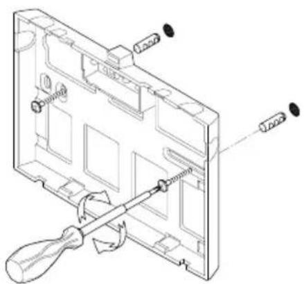
natural_image
Technical line drawing of a device's internal components with screwdriver and screwdriver (no text or symbols)
text_image
Technical diagram showing a mechanical component with labeled parts 1 and 2, likely illustrating a process or assembly.Fig. 4: "Installing the wall bracket"
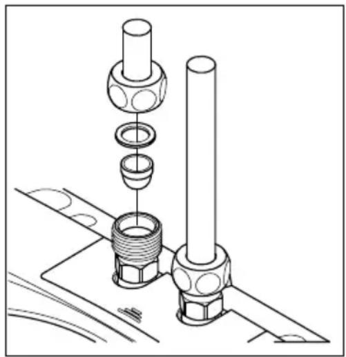
- Rinse the water pipes thoroughly before connecting them to the appliance.
- Connect the water connectors with the relevant tap connectors. The water inlet is indicated in blue on the rating plate (under the cover) and the water outlet in red.
Installation
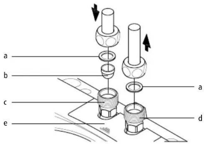
text_image
a b c e a da. Seal
b. Filter
c. Cold water connection (inlet)
d. Hot water connection (outlet)
e. Rating plate cover
Fig. 5: "Connecting the water pipes"
- Make sure that the water pipes do not apply any kind of mechanical pressure on the instantaneous water heater.
- Open the hot water valve of the tap and check all connections for leaks.
2.4 Electrical connection
Fill the appliance with water by repeatedly opening and closing the hot water tap before connecting to electrical power and purge completely. The heating element may be damaged if this is not done!
- ⚠️ Check that the power supply is switched off.
- Make sure that the cross-section of the supply line corresponds to the details in the technical specifications of these instructions.
- Ensure that the dimensions of the circuit breaker do correspond with the cross-section of the connecting cable of the appliance and to the cross-section of the supply line.
- Instantaneous water heater with plug:
a. Check that the socket is connected to the protective earth conductor.
b. Plug the plug into the socket.
Alternatively:
- Instantaneous water heater without plug:
a. Note that according to VDE 0700, an all-pole disconnecting device with a contact opening width of ≥ 3 mm per phase must be provided at the installation end.
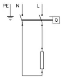
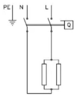
b. Connect the connecting pipe via a junction box to the mains, as shown in the circuit diagram.
Installation
Alternatively:
- Connection to a permanently installed cable:
a. Note that according to VDE 0700, an all-pole disconnecting device with a contact opening width of ≥ 3 mm per phase should be provided at the installation end.
b. The cross-section of the cable must meet the requirements of the minimal cross-section, as mentioned in chapter "Technical specifications". The maximum applicable cross-section is 6 mm ^2 .
c. Open the cover.
d. Dismount the pre-installed connection cable.
e. Route the permanently installed cable through the grommet and connect it as shown in the circuit diagram. Make sure that the grommet fits tightly around the cable to ensure optimal protection against water.
f. Refit the cover on the appliance.

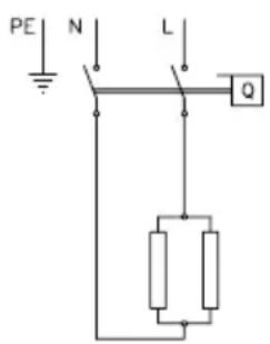
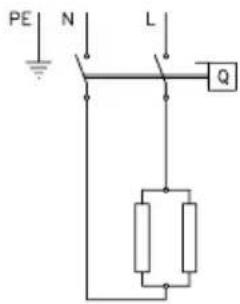
The earth conductor must be connected!
text_image
PE N L QM 3, M 4 (230 V) M 6 (230 V)
text_image
PE N L Q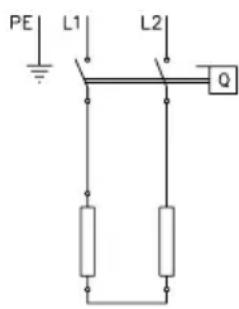
text_image
PE L1 L2 QM 7 (400 V)
Fig. 6: "Circuit diagram"
Installation
2.5 Initial start-up
Do not switch on the electric power at this time!
- To purge the instantaneous water heater, open the hot water tap and wait until the water emerges free of air bubbles.
- In order to obtain an optimum water jet at low flow rates, screw the enclosed special tap aerator into the tap outlet (M 22/24).
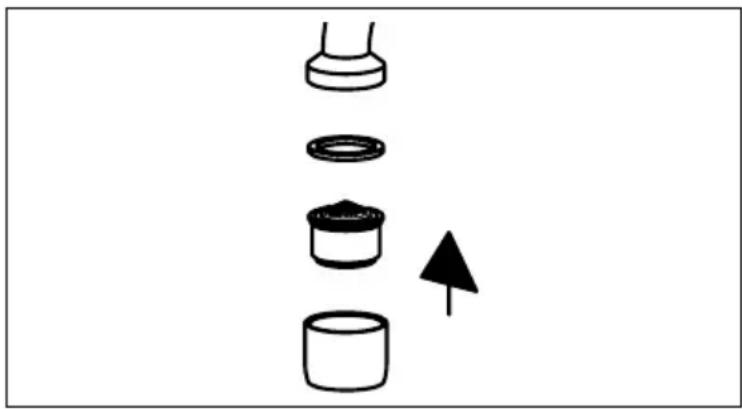
natural_image
Diagram showing four mechanical components with an arrow indicating direction (no text or symbols)Fig. 7: "Fitting the special tap aerator"
- Switch on the electric power.
- Adapt the water flow if necessary, if for example the temperature is not reached. The procedure is described in the chapter "Use".
- Explain the functions and use of the instantaneous water heater to the user and hand over these operating instructions to the user for information and future reference.
- Register the appliance with the customer service department using the registration card or online at www.clage.com.
Use
3. Use
As soon as the hot water tap is opened, the instantaneous water heater switches on automatically. Close the tap and the appliance switches off automatically again.
3.1 Rating plate cover
On the inner part of the cover you can find the name of the application type (1), as well as the serial number (2) and the article number (3).
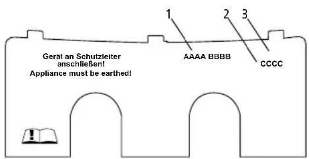
Fig. 8: "Rating plate cover"
3.1.1 Removing the cover
Under this cover, the rating plate and the hood screw are located.
- Push the cover at the corrugation towards the wall bracket.
- At the rear corners press the cover down until the front edge lifts.
- Remove the cover by pulling forward.
natural_image
Technical diagram of a mechanical assembly with two cylindrical components and a labeled arrow (no text or symbols present)
natural_image
Technical diagram showing two mechanical components mounted on a base plate with directional arrows indicating motion (no text or symbols)
natural_image
Technical diagram of a mechanical assembly with two cylindrical components mounted on a base plate, showing directional arrows (no text or symbols)Fig. 9: "Removing the cover"
Use
3.2 Adjusting the water flow and temperature
May only be carried out by a specialist.
Remove the cover, undo the hood screw underneath and remove the hood.
The maximum temperature and flow depend on the conditions at the installation site.
In case of quite low or high cold water temperatures, you may reduce or increase the flow with the adjustment screw to achieve a comfortable outlet temperature. See figure below for direction of rotation:
| Direction of rotation | |||
| Flow | - | + | |
| Temperature | + | - |
Fig. 10: "Adjusting the water flow and temperature"
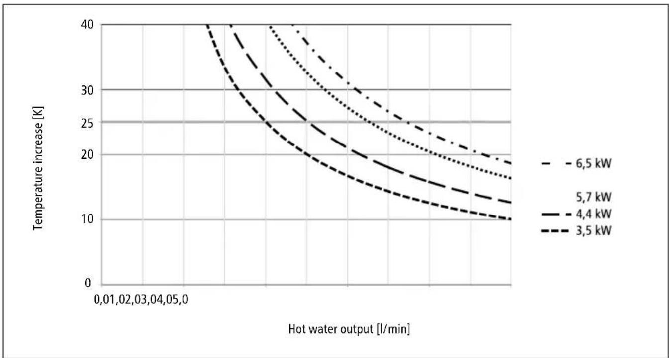
Fig. 11: "Temperature increase and hot water output"
Use
3.3 Changing the strainer
The cold water connection of the instantaneous water heater is equipped with a strainer. Dirt deposited in this strainer can reduce the hot water output. Clean or replace as follows.

- ⚠️ Switch off the power supply to the instantaneous water heater.
- Close the shut-off valve in the inlet pipe.
- Disconnect the water pipe from the water inlet. The water inlet is indicated in blue on the rating plate (under the cover). This can cause water leakage.
- Lever the strainer out of the connection piece of the instantaneous water heater and clean or replace it.
- Insert the clean strainer into the connection piece and connect the water pipe to the water inlet of the instantaneous water heater.
- Purge the instantaneous water heater as described in the chapter "Purging".
- Switch the power supply back on again.
natural_image
Technical line drawing of a mechanical assembly with cylindrical components and threaded ends (no text or symbols)Fig. 12: "Changing the strainer"
3.4 Purging
Each time it is emptied (for example after work on the plumbing system or following repair work on the appliance), the instantaneous water heater must be purged before it is used again.
- Switch off the power supply to the instantaneous water heater.
- To purge the instantaneous water heater, open the hot water tap and wait until the water emerges free of air bubbles.
- Switch the power supply back on again.
3.5 Cleaning and maintenance
- Plastic surfaces and fittings should only be wiped with a damp cloth. Do not use abrasive or chlorine-based cleaning agents or solvents.
- For a good water supply, the outlet fittings (special tap aerators and shower heads) should be unscrewed and cleaned at regular intervals. Every three years, the electrical and plumbing components should be inspected by an authorised professional in order to ensure proper functioning and operational safety at all times.
Troubleshooting
4. Troubleshooting
4.1 Self-help when problems occur
The following table will help you to determine and rectify the reasons for possible problems.
| Problem Possible cause Remedy | ||
| No water flows Water supply | is turned off Open the main water valve and angle valve | |
| Water flows more slowly than expected | Special tap aerator is not fitted Fit the special tap aerator | |
| Water pressure too low Check the water flow pressure | ||
| Dirt in the pipes | Remove any dirt from the filter, angle valve and tap | |
| The appliance switches itself on and off | Water pressure fluctuates, flow rate is too low | Remove any dirt / increase the water flow pressure, close other taps, open angle valve further |
| Water remains cold even though the appliance switches on | Electric supply incorrect Check the electric supply | |
| No voltage Check fuses in the electrical installation | ||
| Faulty heating element | Replace heating element (by authorised technician) | |
| Appliance does not switch on and the water remains cold | Water connections mixed up Check installation | |
| Water flow pressure too low | Check water flow setting (by authorised technician), open angle valve further, check water pressure | |
| Dirt in the pipes Remove dirt from the inlet and outlet pipes | ||
| Hot water temperature varies | Water pressure fluctuates Stabilise the water flow pressure | |
| Supply voltage varies Check the supply voltage | ||
| Hot water temperature is too low | Flow rate is too high or inlet temperature is too low | Adjust the water flow (by authorised technician) |
| Power supply is too low Check the power supply | ||
| M 6: A faulty heating element | Replace heating element (by authorised technician) | |
If the connection cable is damaged, it must be replaced with an original spare cable from the manufacturer by an authorised technician in order to avoid any hazards.
If you cannot rectify the fault with the aid of the troubleshooting table, please contact the customerservice.
Troubleshooting
4.3 Spare parts
When ordering spare parts, please always specify the appliance model and serial number.

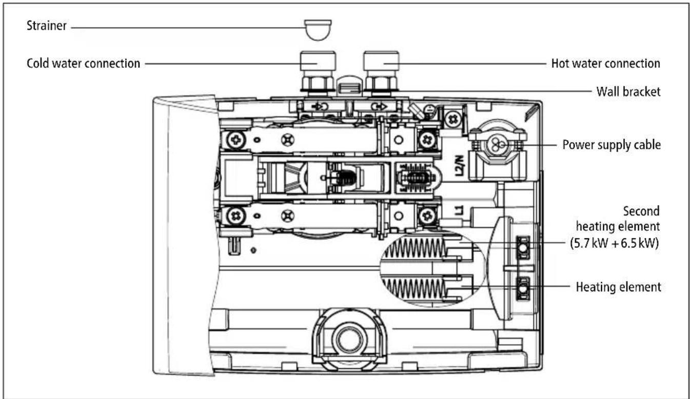
text_image
Strainer Cold water connection Hot water connection Wall bracket Power supply cable Second heating element (5.7 kW + 6.5 kW) Heating elementFig. 13: "Spare parts"
4.2 Customer service address
CLAGE GmbH
After-Sales Service
Pirolweg 1 – 5
21337 Lüneburg
Germany
Phone: +49 4131 8901-40
Fax: +49 4131 8901-41
Email: service@clage.de
If there is a fault with the appliance, please send in the heater with details of the problem and a copy of the sales invoice for examination or repair.
Disposal
5. Disposal
5.1 Disassembly
- ⚠️ Switch off the power supply to the instantaneous water heater.
- Close the shut-off valve in the inlet pipe.
- Disconnect the electrical connection in the appliance junction box or disconnect the protective earth plug if the appliance is fitted with a plug.
- Disconnect the water pipes from the connectors of the appliance. This can cause water leakage.
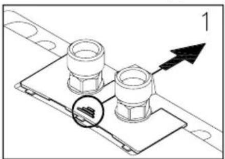
- Remove the appliance from the wall bracket. To do so, insert the tip of a wide screwdriver as far as it will go into the latch between the water connection pieces and push the latch slightly upwards. Tilt the appliance forward by max. 15° and remove it by lifting it upwards.
- Unscrew the wall bracket from the wall.
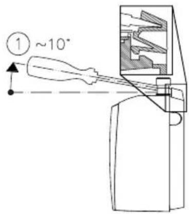
text_image
① ~10°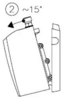
text_image
② ~15°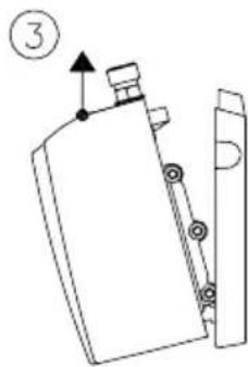
text_image
③Fig. 14: "Removing the appliance from the wall bracket"
5.2 Environment and recycling
Your product was manufactured from high-quality, reusable materials and components. Please respect in case of discarding that electrical devices should be disposed of separately from household waste at the end of their service life. Therefore, please take this device to a municipal collection point that accepts electronic scrap. Disposing it correctly will support environmental protection and will prevent any potential negative effects on human beings and the environment that could arise from inappropriate handling of these devices at the end of their service life. Please contact your local authority for further details of your nearest designated collection point or recycling site.
Business customers: If you wish to discard equipment, please contact your dealer or supplier for further information.
Sommaire
natural_image
Technical line drawing of a device's internal components with screwdriver and screwdriver (no text or symbols)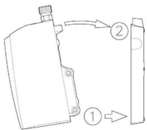
text_image
Technical diagram showing a mechanical component with labeled parts 1 and 2, likely illustrating a process or assembly.M 3, M 4 (230 V) M 6 (230 V)

text_image
PE N L Q
text_image
PE L1 L2 Qnatural_image
Diagram showing four mechanical components with an arrow indicating direction (no text or symbols)natural_image
Technical diagram of a mechanical assembly with two cylindrical components and a labeled arrow (no text or symbols present)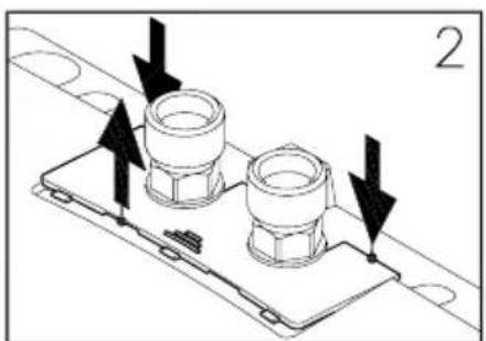
natural_image
Technical diagram showing two mechanical components mounted on a base plate with directional arrows indicating movement (no text or symbols)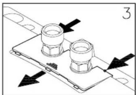
natural_image
Technical diagram of a mechanical assembly with two cylindrical components mounted on a base plate, showing directional arrows (no text or symbols)natural_image
Technical line drawing of a mechanical assembly with cylindrical components and threaded ends (no text or symbols)natural_image
Technical line drawing of a computer case with screwdriver and screwdriver (no text or symbols)
text_image
Technical diagram showing a mechanical component with labeled parts ① and ②, likely illustrating a process or assembly.M 3, M 4 (230 V) M 6 (230 V)

text_image
PE N L Q
text_image
PE L1 L2 QM 7 (400 V)
Afb. 6: "Schakelschema"
natural_image
Diagram showing four mechanical components with an arrow indicating direction (no text or symbols)natural_image
Technical diagram of a mechanical assembly with two cylindrical components and an arrow indicating direction (no text or symbols)
natural_image
Technical diagram showing two mechanical components mounted on a base plate with directional arrows indicating assembly or movement (no text or symbols present)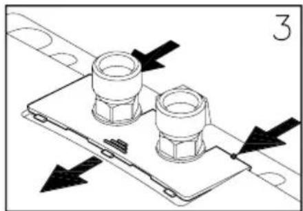
natural_image
Technical diagram of a mechanical assembly with two cylindrical components mounted on a base plate, showing directional arrows (no text or symbols)natural_image
Technical line drawing of a mechanical assembly with cylindrical components and threaded ends (no text or symbols)Sustainable Development Agency
text_image
① ~10° ② ~15° ③natural_image
Technical line drawing of a mechanical assembly with screwdriver and housing (no text or symbols)
text_image
Technical diagram showing a mechanical component with labeled parts 1 and 2, likely illustrating a process or assembly.M 3, M 4 (230 V) M 6 (230 V)

text_image
PE N L Q
text_image
PE L1 L2 Qnatural_image
Diagram showing four mechanical components with an arrow indicating direction (no text or symbols)natural_image
Technical diagram showing two bolted components mounted on a base plate with an arrow indicating direction (no text or symbols)
natural_image
Technical diagram showing two mechanical components mounted on a base plate with directional arrows indicating motion (no text or symbols)
natural_image
Technical diagram of a mechanical assembly with two cylindrical components mounted on a base plate, showing directional arrows (no text or symbols)natural_image
Technical line drawing of a mechanical assembly with cylindrical components and threaded ends (no text or symbols)Rys. 12: »Wymiana sitka filtra«
3.4 Odpowietrzanie
natural_image
Technical line drawing of a computer monitor case with screwdriver and adjustment knobs (no text or labels)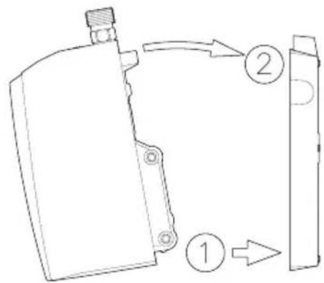
text_image
Technical diagram showing a mechanical component with labeled parts 1, 2, and directional arrows indicating flow or movement.M 3, M 4 (230 V) M 6 (230 V)

text_image
PE N L Q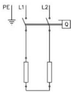
text_image
PE L1 L2 QM 7 (400 V)
Obr. 6: «Schéma zapojení»
CS
natural_image
Diagram showing four mechanical components with an arrow indicating direction (no text or symbols)natural_image
Technical diagram showing two bolted components mounted on a base plate with an arrow indicating direction (no text or symbols)
natural_image
Technical diagram of a mechanical assembly with two cylindrical components and directional arrows indicating motion (no text or symbols)
natural_image
Technical diagram of a mechanical assembly with two cylindrical components mounted on a base plate, showing directional arrows (no text or symbols)natural_image
Technical line drawing of a mechanical assembly with cylindrical components and threaded ends (no text or symbols)natural_image
Technical line drawing of a mechanical assembly with screwdriver and mounting holes (no text or symbols)
text_image
Technical diagram showing a mechanical component with labeled parts 1 and 2, likely illustrating a process or assembly.M 3, M 4 (230 V) M 6 (230 V)

text_image
PE N L Q
text_image
PE L1 L2 Qnatural_image
Diagram showing four mechanical components with an arrow indicating direction (no text or symbols)natural_image
Technical diagram of a mechanical assembly with two cylindrical components and a labeled arrow (no text or symbols present)
natural_image
Technical diagram of a mechanical assembly with two cylindrical components and directional arrows indicating motion (no text or symbols)
natural_image
Technical diagram of a mechanical assembly with two cylindrical components mounted on a base plate, showing directional arrows (no text or symbols)Obr. 9: »Odobratiekrytky«
Používanie
3.2 Nastavenie množstva vody a teploty
natural_image
Technical line drawing of a mechanical assembly with cylindrical components and threaded ends (no text or symbols)natural_image
Technical line drawing of a mechanical assembly with screwdriver and mounting holes (no text or symbols)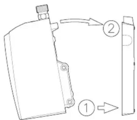
text_image
Technical diagram showing a mechanical component with labeled parts 1 and 2, likely illustrating a process or assembly.M 3, M 4 (230 V) M 6 (230 V)
text_image
PE N L Q
text_image
PE L1 L2 Qnatural_image
Diagram showing four mechanical components with an arrow indicating direction (no text or symbols)natural_image
Technical diagram of a mechanical assembly with two cylindrical components and an arrow indicating direction (no text or symbols)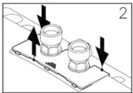
natural_image
Technical diagram showing two mechanical components mounted on a base plate with directional arrows indicating assembly or movement (no text or symbols present)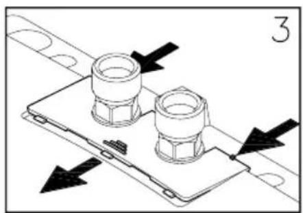
natural_image
Technical diagram of a mechanical assembly with two cylindrical components mounted on a base plate, showing directional arrows (no text or symbols)line
| Varmtvannsytelse [l/min] | 6.5 kW | 5.7 kW | 4.4 kW | 3.5 kW | | ------------------------ | ------ | ------ | ------ | ------ | | 0.01 | 40 | 40 | 40 | 40 | | 0.02 | 38 | 38 | 38 | 38 | | 0.03 | 36 | 36 | 36 | 36 | | 0.04 | 34 | 34 | 34 | 34 | | 0.05 | 32 | 32 | 32 | 32 | | 0.1 | 30 | 30 | 30 | 30 | | 0.2 | 28 | 28 | 28 | 28 | | 0.3 | 26 | 26 | 26 | 26 | | 0.4 | 24 | 24 | 24 | 24 | | 0.5 | 22 | 22 | 22 | 22 | | 0.6 | 20 | 20 | 20 | 20 | | 0.7 | 18 | 18 | 18 | 18 | | 0.8 | 16 | 16 | 16 | 16 | | 0.9 | 14 | 14 | 14 | 14 | | 1.0 | 12 | 12 | 12 | 12 | | 1.1 | 10 | 10 | 10 | 10 | | 1.2 | 9 | 9 | 9 | 9 | | 1.3 | 8 | 8 | 8 | 8 | | 1.4 | 7 | 7 | 7 | 7 | | 1.5 | 6 | 6 | 6 | 6 | | 1.6 | 5 | 5 | 5 | 5 | | 1.7 | 4 | 4 | 4 | 4 | | 1.8 | 3 | 3 | 3 | 3 | | 1.9 | 2 | 2 | 2 | 2 | | 2.0 | 1 | 1 | 1 | 1 | | 2.1 | 0.5 | 0.5 | 0.5 | 0.5 | | 2.2 | 0.3 | 0.3 | 0.3 | 0.3 | | 2.3 | 0.2 | 0.2 | 0.2 | 0.2 | | 2.4 | 0.1 | 0.1 | 0.1 | 0.1 | | 2.5 | 0.05 | 0.05 | 0.05 | 0.05 | | 2.6 | 0.03 | 0.03 | 0.03 | 0.03 | | 2.7 | 0.02 | 0.02 | 0.02 | 0.02 | | 2.8 | 0.01 | 0.01 | 0.01 | 0.01 | | 2.9 | 0.005 | 0.005 | 0.005 | 0.005 | | 3.0 | 0.003 | 0.003 | 0.003 | 0.003 | | 3.1 | 0.002 | 0.002 | 0.002 | 0.002 | | 3.2 | 0.0015 | 0.0015 | 0.0015 | 0.0015 | | 3.3 | 0.001 | 0.001 | 0.001 | 0.001 | | 3.4 | 0.0008 | 0.0008 | 0.0008 | 0.0008 | | 3.5 | 0.0006 | 0.0006 | 0.0006 | 0.0006 | | 3.6 | 0.0005 | 0.0005 | 0.0005 | 0.0005 | | 3.7 | 0.0004 | 0.0004 | 0.0004 | 0.0004 | | 3.8 | 0.0003 | 0.0003 | 0.0003 | 0.0003 | | 3.9 | 0.0002 | 0.0002 | 0.0002 | 0.0002 | | 4.0 | 0.0 | nan | nan | nan | | Peak | - | - | - | - | | Final | - | - | - | - | | Current | - | - | - | - | | Temperature (K) | | Current (K) | | Temperature (L/min) | | Current (K) | | Temperature (l/min) | | Current (K) | | Temperature (l/min) | | Current (kW) | | Current (kW) | | Current (kW) | | Current (kW) | | Current (kW) | | Current (kW) | | Current (kW) | | Current (kW) | | Current (kW) | | Current (kW) | | Current (kW) | | Current (kW) < Current >| | Current < Current >| | Current < Current >| | Current < Current >| | Current < Current >| | Current < Current >| | Current < Current >| | Current < Current >| | Current < Current >| | Current < Current >| | Current < Current >| | Current < Current >| | Current < Current >| | Current < Current >| | Current < Current >| | Currentnatural_image
Technical line drawing of a mechanical assembly with cylindrical components and threaded ends (no text or symbols)Fig. 12: «Skifte filtersil»
3.4 Avlufting
natural_image
Technical line drawing of a mechanical assembly with screwdriver and mounting holes (no text or symbols)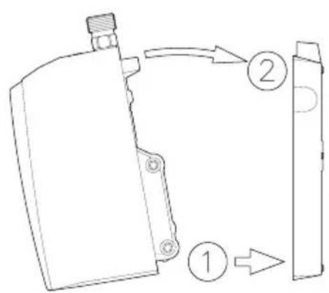
text_image
Technical diagram showing a device with labeled parts and directional arrows indicating flow or movement.M 3, M 4 (230 V) M 6 (230 V)

text_image
PE N L Q
text_image
PE L1 L2 QM 7 (400 V)
Bild 6: "Kopplingsschema"
natural_image
Diagram showing four stages of a mechanical or industrial process: top, bottom, middle, and bottom (no text or symbols)natural_image
Technical diagram showing two bolted components mounted on a base plate with an arrow indicating direction (no text or symbols)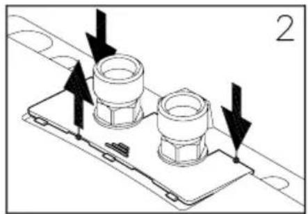
natural_image
Technical diagram showing two mechanical components mounted on a base plate with directional arrows indicating assembly or movement (no text or symbols present)
natural_image
Technical diagram of a mechanical assembly with two cylindrical components mounted on a base plate, showing directional arrows (no text or symbols)Bild 9: "Avtagning i skyddet"
Användning
natural_image
Technical line drawing of a mechanical assembly with cylindrical components and threaded ends (no text or symbols)Bild 12: "Byte av filtersilen"
Felavhjälpning
4. Felavhjälpning
Switchboard +46 8 80 90 00
Fax: +46 8 80 90 73
www.zeta.se
zander.ingestrom@zeta.se
text_image
SV ① ~10° ② ~15° ③natural_image
Technical line drawing of a device's internal components with screwdriver and screwdriver (no text or labels)
text_image
Technical diagram showing a mechanical component with labeled parts 1 and 2, likely illustrating a process or assembly.M 3, M 4 (230 V) M 6 (230 V)

text_image
PE N L Q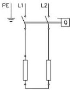
text_image
PE L1 L2 Qnatural_image
Diagram showing four mechanical components with an arrow indicating direction (no text or symbols)natural_image
Technical diagram of a mechanical assembly with two cylindrical components and a labeled arrow (no text or symbols present)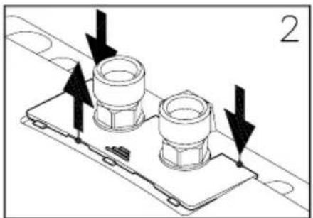
natural_image
Technical diagram showing two mechanical components mounted on a base plate with directional arrows indicating assembly or movement (no text or symbols present)
natural_image
Technical diagram of a mechanical assembly with two cylindrical components mounted on a base plate, showing directional arrows (no text or symbols)natural_image
Technical line drawing of a mechanical assembly with cylindrical components and threaded ends (no text or symbols)natural_image
Technical line drawing of a device's internal components with screwdriver and screwdriver (no text or symbols)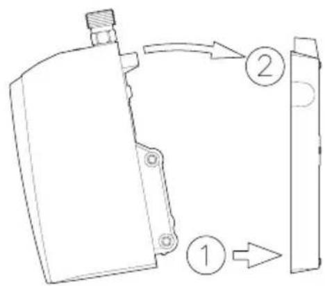
text_image
Technical diagram showing a mechanical component with labeled parts 1, 2, and directional arrows indicating flow or movement.M 3, M 4 (230 V) M 6 (230 V)

text_image
PE N L Q
text_image
PE L1 L2 Qnatural_image
Diagram showing four mechanical components with an arrow indicating direction (no text or symbols)natural_image
Technical diagram of a mechanical assembly with two cylindrical components and a labeled arrow (no text or symbols present)
natural_image
Technical diagram of a mechanical assembly with two cylindrical components and directional arrows indicating motion (no text or symbols)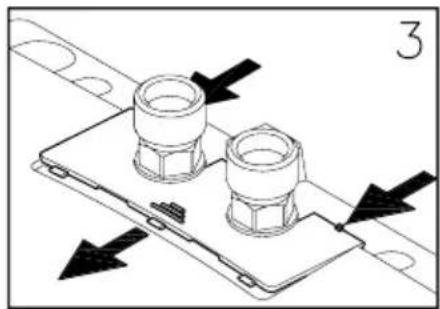
natural_image
Technical diagram of a mechanical assembly with two cylindrical components mounted on a base plate, showing directional arrows (no text or symbols)natural_image
Technical line drawing of a mechanical assembly with cylindrical components and threaded ends (no text or symbols)text_image
Technical diagram showing two views of a device with screwdriver and labeled parts, including numbered annotations.M 3, M 4 (230 V) M 6 (230 V)

text_image
PE N L Q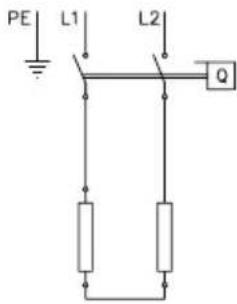
text_image
PE L1 L2 QM 7 (400 V)
natural_image
Diagram showing four mechanical components with an arrow indicating direction (no text or symbols)natural_image
Technical diagram showing two bolted components mounted on a base plate with an arrow indicating direction (no text or symbols)
natural_image
Technical diagram showing two mechanical components mounted on a base plate with directional arrows indicating motion (no text or symbols)
natural_image
Technical diagram of a mechanical assembly with two cylindrical components mounted on a base plate, showing directional arrows (no text or symbols)natural_image
Technical line drawing of a mechanical assembly with cylindrical components and threaded ends (no text or symbols)natural_image
Technical line drawing of a device internal structure with screwdriver and screwdriver (no text or symbols)
text_image
Technical diagram showing a mechanical component with labeled parts ① and ②, likely illustrating a process or assembly.M 3, M 4 (230 V) M 6 (230 V)

text_image
PE N L Q
text_image
PE L1 L2 Qnatural_image
Diagram showing four types of mechanical components or parts stacked vertically, with one component highlighted by an arrow (no text or symbols present)natural_image
Technical diagram of a mechanical assembly with two cylindrical components and an arrow indicating direction (no text or symbols)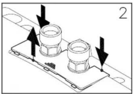
natural_image
Technical diagram showing two mechanical components mounted on a base plate with directional arrows indicating assembly or movement (no text or symbols present)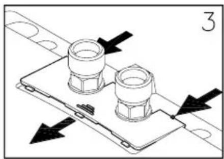
natural_image
Technical diagram of a mechanical assembly with two cylindrical components mounted on a base plate, showing directional arrows (no text or symbols)Fig. 9: «Retirada del panel»
Empleo
natural_image
Technical line drawing of a mechanical assembly with cylindrical components and threaded ends (no text or symbols)Fig. 12: «Cambio del tamiz de filtro»
3.4 Purga
text_image
① ~10° ② ~15° ③Fig. 14: «Retirada del aparato del soporte de pared»
ES
> en Product data sheet in accordance with EU regulation
(a) Brand name or trademark, (b.1) Model, (b.2) Type, (c) Specified load profile, (d) Energy-efficiency class, (e) Energy-efficiency, (f) Annual power consumption, (g) Additional load profile, the appropriate energy-efficiency and the annual power consumption, if applicable, (h) Temperature setting for the temperature controller, (i) Sound power level, internal.
Additional notes: All specific precautions for assembly, installation, maintenance and use are described in the operating and installation instructions. All data in this product data sheet are determined by applying the specifications of the relevant European directives. Differences to other product information listed elsewhere may result in different test conditions. The power consumption was determined in compliance with standardized measurement method based on EU guidelines. The real energy consumption is pending on individual requirements.