DEX Next - Boiler Clage - Free user manual and instructions
Find the device manual for free DEX Next Clage in PDF.
| Product type | Electronic instantaneous water heater |
| Brand | Clage |
| Model | DEX Next |
| Rated power / current | 18 kW / 26A to 27 kW / 39A (configurable) |
| Electrical connection | 3~/PE 380-415 V AC, 400 V AC |
| Required cable cross-section | 4.0 mm² (18-21 kW), 6.0 mm² (24-27 kW) |
| Hot water production (Δt=28 K) | 9.2 to 13.8 l/min (depending on power) |
| Nominal capacity | 0.4 l |
| Nominal pressure | 1.0 MPa (10 bar) |
| Temperature range | 20 °C to 60 °C |
| Max. inlet temperature | 70 °C |
| Start-up flow rate | 1.5 l/min |
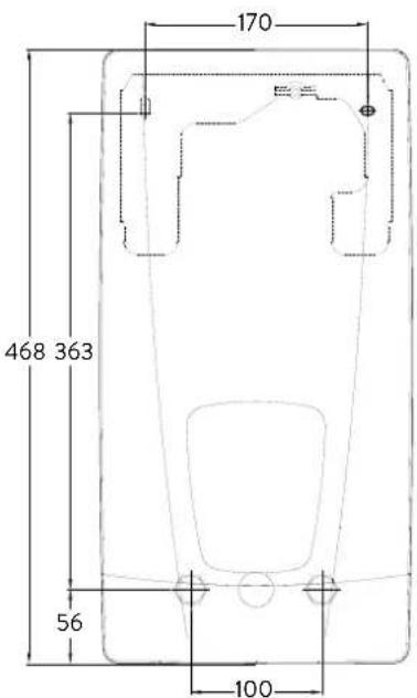
| Dimensions (H x W x D) | 468 x 170 x 363 mm |
| Weight (filled with water) | 4.2 kg |
| Protection class | IP25 |
| Energy efficiency class | A |
| Main functions | E-paper display, touch keys, 4 user profiles, predefined applications, consumption statistics, optional radio remote control |
| Safety | Temperature limiter (STB), pressure limiter (SDB), frost protection, PIN code lock |
| Maintenance and cleaning | Cleaning the inlet filter, bleeding after work, descaling outlets |
| Water connection | G 1/2 inch |
Frequently Asked Questions - DEX Next Clage
User questions about DEX Next Clage
0 question about this device. Answer the ones you know or ask your own.
Ask a new question about this device
Download the instructions for your Boiler in PDF format for free! Find your manual DEX Next - Clage and take your electronic device back in hand. On this page are published all the documents necessary for the use of your device. DEX Next by Clage.
USER MANUAL DEX Next Clage
E-convenience instant water heater DEX Next
de > 2
en > 22
fr > 41
nl > 61
pt > 80
es > 99
pl > 118
ru > 137
cs > 157
sk > 176
bg > 195
sr > 214
natural_image
White industrial water heater with digital display showing 38-degree angle and control buttons (no text or symbols on main body)Inhaltsverzeichnis
Gebrauchsanleitung
natural_image
White industrial water heater with digital display showing 38% and control buttons (no text or symbols on main body)natural_image
Symbol of a trash bin crossed out by two diagonal lines (no text or numbers present)natural_image
Simple black-and-white line drawing of a tree with two horizontal lines below (no text or symbols)Energiespartipp
text_image
Warning symbol with exclamation mark inside trianglenatural_image
3D CAD model of a mechanical housing or enclosure with internal grid structure and mounting holes (no text or symbols visible)
natural_image
Technical illustration of VDX pipe fittings and connectors (no text or symbols)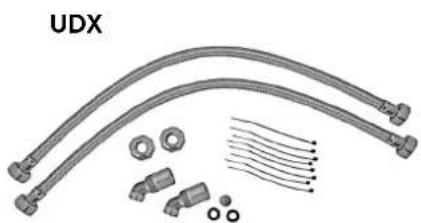
natural_image
Product assembly of UDX connectors and wiring (no text or symbols visible)Zu beachten sind:
natural_image
Technical line drawing of a mechanical bracket assembly (no text or symbols)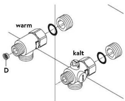
text_image
warm kalt Dnatural_image
Technical line drawing of a mechanical assembly with no visible text or symbolsGerät montieren
natural_image
Technical line drawing of a mechanical bracket assembly (no text or symbols)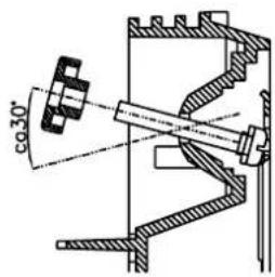
text_image
co30°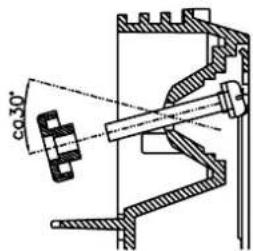
text_image
co 30°
text_image
180mm 60mm 8mm

text_image
Technical diagram of an electrical enclosure with labeled component 'S' and directional arrow indicating flow or movement.text_image
GEPRÜFT APPROVED
Multiple Power System MPS®:
text_image
Technical diagram showing a disassembled electronic device with labeled parts and a tool inserted into it.text_image
Technical diagram of an electronic device with labeled components, showing internal circuitry and assembly steps.Sperrfunktion
text_image
Technical diagram showing a mechanical component with an inset close-up of a textured surface, illustrating assembly or assembly process.Operation instruction
- Description of the appliance 23
- Environment and recycling 23
- How to use 24
Main screen....24
Main menu....25
Statistics 25
Settings 25
User....27
Device Information 27
Top-up heating 27
How to save energy....27
Venting after maintenance work....27
Cleaning and maintenance....27
- Trouble-shooting and service....28
- Product data sheet in accordance with EU regulation - 812/2013 814/2013 29
Installation instruction
- Overview....30
- Technical specifications ....31
- Dimensions.... 31
- Installation....32
Installation site....32
Mounting accessories 32
Installing the wall bracket....33
Installing connection pieces....33
Installing the appliance 34
- Direct connection 35
- Electrical connection 36
Wiring diagram....36
Structural prerequisites 36
Load shedding relay....36
Electrical connection from below....37
Electrical connection from above....37
- Initial operation 38
Selection of power rating....38
Reinstallation 38
Shower application 39
Locking function 39
- Maintenance work....40
Cleaning and replacing the filter strainer 40
Cleaning and replacing the filter strainer if direct connected....40
The documents supplied with the device must be stored carefully.
Registration
Register your device online on our website and benefit from our services under warranty.
Your full details help our customer service process your request as fast as possible.
For online registration, just follow the link below or use the QR code with your smartphone or tablet.
https://partner.clage.com/en/service/device-registration/

Operation instruction
Note: Carefully read the enclosed safety instructions through in full before the appliance is installed, put into service and used and follow them in the further steps and during use!
1. Description of the appliance

natural_image
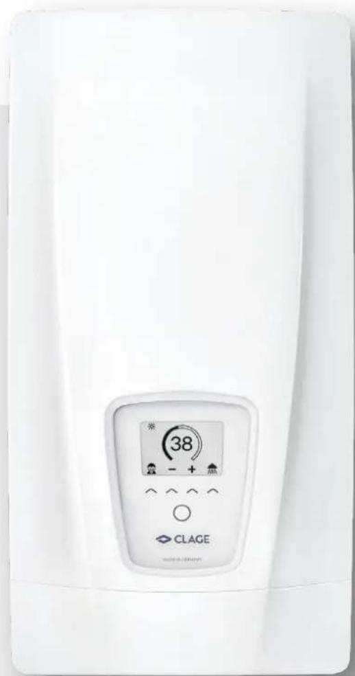
White industrial water heater with digital display showing 38% and control buttons (no text or symbols beyond branding)The E-convenience instant water heater DEX Next is a fully electronically controlled instantaneous water heater with graphics-enabled e-paper display and sensor keys for a convenient and efficient water supply to one or more tap outlets.
Its electronic control regulates the power consumption depending on the selected outlet temperature, the respective inlet temperature and the flow rate, thus reaching the set temperature exactly to the degree and keeping it constant in case of water pressure fluctuations. The required outlet temperature can be entered via the sensor keys within a range between 20 °C and 60 °C and can be read off the e-paper display.
The DEX Next has an intuitive menu guide where different user profiles can be set up and where collected data can be read out
The inlet temperature can be up to 70 °C so that operation in connection with reheating, e.g. in solar systems, is possible.
It is possible to use the instantaneous water heater in combination with an external load shedding relay for electronically controlled instantaneous water heaters (refer to installing instructions).
As soon as you open the hot water tap, the instantaneous water heater switches on auto ma ti cally. When the tap is closed, the appliance automatically switches off. The water heater is operated at the device itself or with an optional wireless remote control.
2. Environment and recycling
natural_image
Symbol of a trash bin crossed out by two diagonal lines (no text or numbers present)This product was manufactured climate neutrally according to Scope 1 + 2. We recommend the purchase of 100% green electricity to make the operation climate neutral as well.
Disposal of transport and packaging material: For smooth transport your product is carefully packed. The disposal of the transport material is carried out by the specialist tradesman or the specialist trade. Separate the sales packaging according to materials separated according to materials via one of the dual systems in Germany.
Disposal of old products: Your product was manufactured from high-quality, reusable materials and components. Products marked with the crossed-out wheeled bin symbol must be disposed of separately from household waste at the end of their service life. Therefore, take this product to us as the manufacturer or to one of the municipal collection points that recycle used electronic devices. This proper disposal serves to protect the environment and prevents possible harmful effects on humans and the environment that could result from improper handling of the products at the end of their service life. For more detailed information on disposal, please contact your nearest collection point or recycling centre or your local council.
Business customers: If you wish to discard equipment, please contact your dealer or supplier for further information.
For disposal outside Germany, please also observe the local regulations and laws.
3. How to use
Main screen
The e-paper display changes automatically to main screen approx. 60 seconds after activation or operation.
Tab the sensor keys to select user profiles or applications or change the temperature.
text_image
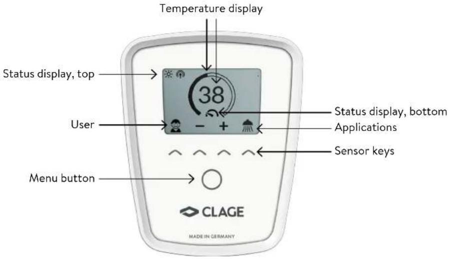
Temperature display Status display, top 38 User Status display, bottom Applications Sensor keys Menu button CLAGE MADE IN GERMANYTemperature display
The scale ring fills up as the temperature setting is increased. In addition, the target temperature is displayed in ^ C in the middle of the display.
Temperature setting
The desired temperature can be selected via the two middle sensor keys within a range of 20^ C to 60^ C. Tapping once changes the temperature by 1^ C, in the comfort range between 35 and 43^ C by 0.5^ C. If the temperature is set below 20^ C, the symbol—appears in the temperature display and the appliance switches off the heating function.
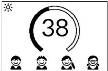
User selection
Up to four user profiles can be created. Every user has the option to save his desired temperatures for the different application in his profile. The user profiles can be selected by tapping on the left sensor key and than tap the key under the profile picture (to adapt profile, see Section "User").
Applications
Preset applications can be selected here. Simply tap on the right sensor key to open the selection. Tap on the sensor key under an application symbol to activate it.
The temperatures are set at the factory to the following values: hand wash = 35°C,
shower = 38°C, bath tub = 40°C, hot water = 48°C
To change the values select an application and set the new temperature. Than press and hold the sensor key under your profile picture or the application for two seconds.
Status display, top
Control lock active (PIN)
The inlet temperature exceeds the target value (appliance does not heat up)
Optional remote control or Home Server is installed. The appliance can be controlled remotely
Status display, bottom
Display area for functions which require confirmation from the user or which are of great significance.
Maintenance: The appliance detected an error. Select "Info" in the Main menu to get further informations.
text_image
38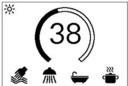
text_image
383. How to use
text_image
Statistics User Settings Info OK
text_image
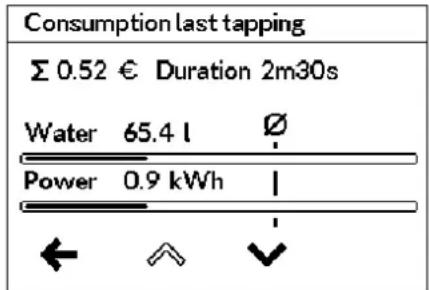
Consumption last tapping Σ 0.52 € Duration 2m30s Water 65.4 l Ø Power 0.9 kWh | ← ↗ ↓MAX Maximum temperature reached: The temperature cannot be increased any further since the set temperature limit has been reached. The temperature limit can be changed in the main menu via "Settings".
Heating activated: As soon as the appliance heats water, this symbol appears.
Power limit: The full output of the instantaneous water heater does not suffice to heat the tapped quantity of water to desired temperature. Reduce the quantity of warm water at the tap.
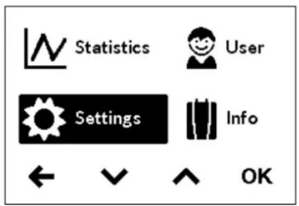
Main menu
Press the menu button to enter the main menu. All function menus and saved values of the appliance can be selected from here.
Statistics
In the statistics the consumption and usage data are captured by the appliance and displayed in graph format:
Water consumption
Power consumption
Σ Total consumption costs
Select ▲ or ▼ to scroll through the different periods. The consumptions are displayed in diagrams over a period from the last drawing of water or the total consumption.
Note: The consumption data are not suitable for billing purposes.
Settings
This menu is used for the basic configuration on the appliance. Select ▲ to √ scroll through the different menu items and tap "OK" to change settings directly or go to submenus.
Temperature Unit: Defined as °C.
Language: Select the menu language.
Sound: Activate / deactivate operating sounds.
Note: Alarm signals and instruction sounds can not be disabled.
Currency: Select a currency symbol.
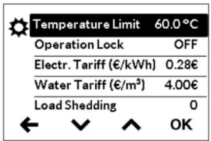
text_image
Temperature Limit 60.0°C Operation Lock OFF Electr. Tariff (€/kWh) 0.28€ Water Tariff (€/m³) 4.00€ Load Shedding 0 ← ↙ ↑ OKTemperature Limit: The temperature limit can be activated / deactivated in this menu and the maximum warm water temperature can be limited to a desired value within the temperature setting range.
Note: If the instantaneous water heater supplies a shower, then the maximum temperature was limited during the installation of the appliance and can not be changed.
3. How to use
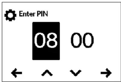
Operation Lock: Secure your settings with a four-digit PIN.
Note: The operation lock can only be deactivated with the correct PIN under "Protected Sections" or under "Delete PIN". If you should forget your PIN, please contact Customer Services.
PIN Entry: Use ↗ or ↘ to select digits from 00 to 99. To move to the next or previous digit, select ← or →. Once you have selected both digits, confirm by →. The PIN must be reentered and confirmed by "OK" as a security measure.
If both entries match, the range of the control lock can be set.
text_image
Enter PIN 08 00 ← ^ √ →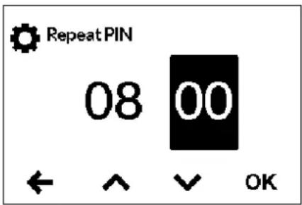
text_image
RepeatPIN 08 00 ← ↑ ↓ OK- Settings: Automatically active as soon as a password has been generated. Users can only access the settings menu with a PIN.
- All: PIN entry is required to operate the appliance.
- OFF: The PIN is deleted and the appliance can be operated freely.
Electricity price (currency/kWh): Specify the electricity price of your own electricity supplier.
Water price (currency/m ^3 ): Specify the water price of your own water supplier.
| Value | Description |
| 0 | Operation without load shedding relay, factory setting |
| 1 | Operation with normal load shedding relay |
| 2 | Operation with sensitive load shedding relay |
Load Shedding: If further three-phase appliances are connected, a load shedding relay designed for electronic instantaneous water heaters (CLAGE no. 82250) can be connected to phase conductor L2. This relay ensures the operation of the water heater by switching off other consumers until the end of heating operation.
Select "OK" to activate the edit mode. To set a value of "0", "1" or "2" press and hold ▲ or ▼ for two seconds.
Operating mode 1 must be selected first, thus to check the correct operation of the load shedding relay at low appliance output (35 degree celsius setpoint and low water flow rate). Mode 2 must be selected if the load shedding relay flickers.
Factory Settings: All factory settings can be recalled. Temperature limit for showering and load shedding are not affected.
Note: All customised user profiles and power and water prices entered, are deleted.
Delete Statistics: Use this function to delete all previously collected statistical data. Deleted statistical data cannot be restored.
3. How to use
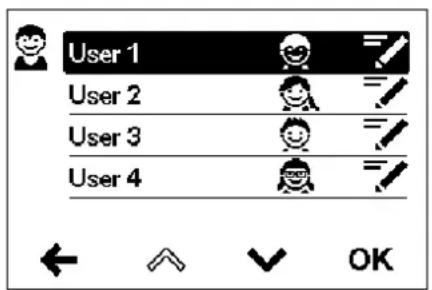
text_image
User 1 User 2 User 3 User 4 OK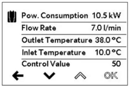
text_image
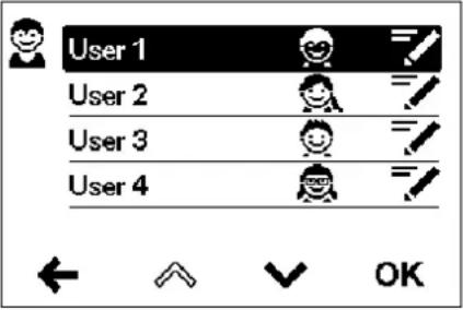
Pow. Consumption 10.5 kW Flow Rate 7.0 l/min Outlet Temperature 38.0 °C Inlet Temperature 10.0 °C Control Value 50 ← √ ↑ OKUser
Each of the four user profiles can be provided with their own profile image. This image appears in the main screen.
In the main screen, every user can set up and save his own desired temperatures for the different applications.
Device Information
The current status and appliance data are listed here. Use the sensor keys to scroll through the different information values.
Top-up heating
When operating with preheated water (e.g. with solar systems), you must ensure that the inlet temperature does not exceed 70^ C.
If the inlet temperature exceeds the setpoint, the appliance is not providing any output. The symbol ⚙ is displayed in the main screen

natural_image
Simple black-and-white line drawing of a tree with two horizontal lines below (no text or symbols)How to save energy
Set the exact temperature you need on the appliance and open the hot water tap. Once you feel that the water is too hot, do not add any cold water and, instead, enter a lower temperature on the appliance. If you were to add cold water, the water already heated would cool down again and valuable energy would be wasted. Moreover, the cold water added in the tap is not covered by the control range of the electronic circuitry, with the result that temperature constancy is no longer guaranteed.

Venting after maintenance work
This instantaneous water heater features an automatic air bubble protection to prevent it from inadvertently running dry. Nevertheless, the appliance must be vented before using it for the first time. Each time the appliance is emptied (e.g. after work on the plumbing system, if there is a risk of frost or following repair work), the appliance must be re-vented before it is used again.
- Disconnect the instantaneous water heater from the mains (e.g. via deactivating the fuses).
- Unscrew the jet regulator on the outlet fitting and open the cold water tap valve to rinse out the water pipe and avoid contaminating the appliance or the jet regulator.
- Open and close the hot water tap until no more air emerges from the pipe and all air has been eliminated from the water heater.
- Only then should you re-connect the power supply again (e.g. via activating the fuses) to the instantaneous water heater and screw the jet regulator back in.
- The appliance activates the heater after approx. 10 seconds of continuous water flow.
Cleaning and maintenance
- Plastic surfaces and fittings should only be wiped with a damp cloth. Do not use abrasive or chlorine-based cleaning agents or solvents.
- For a good water supply, the outlet fittings (e.g. jet regulators and shower heads) should be unscrewed and cleaned at regular intervals. Every three years, the electrical and plumbing components should be inspected by an authorised professional in order to ensure proper functioning and operational safety at all times.
4. Trouble-shooting and service
EN

text_image
Warning symbol with exclamation mark inside triangleRepairs must only be carried out by authorised professionals.
If a fault in your appliance cannot be rectified with the aid of this table, please contact the service organisation of your importer or the Central Customer Service Department. Please have the details of the typeplate at hand.
CLAGE GmbH
After-Sales Service
Pirolweg 4
21337 Lüneburg
Germany
Phone: +49 4131 8901-400
Email: service@clage.de
This instantaneous water heater was manufactured conscientiously and checked several times before delivery. Should malfunctions nevertheless occur, it is usually only due to a bagatelle. First attempt to switch the house fuses off and on again in order to reset the electronics. Next, try to remedy the problem with reference to the following table. In doing so, you will avoid unnecessary expense of customer service assistance.
| DEX Next | ||
| Problem Cause Solution | ||
Water stays cold, touch display shows power break screen  | Master fuse tripped Renew | or activate fuse |
| Safety pressure cut-out tripped | Contact customer service | |
| Water stays cold. display shows error symbol [ZSDW] | The appliance has detected an error | Switch fuses off and on. If symbol “wrench” is still indicated, contact customer service |
| Flow rate of hot water too weak | Outlet fitting dirty or calcified | Clean shower head, jet regulator or sieves |
| Fine filter dirty or calcified | Let clean fine filter by customer service | |
| Selected temperature is not reached | Power limit reached | Decrease the warm water flow at the tap |
| Cold water has been added via the tap | Tap hot water only; set temperature, check outlet temperature | |
| Sensor keys does not respond correctly or only sporadically | Display glass is wet | Dry display by wiping it with a soft cloth |
- Product data sheet in accordance with EU regulation - 812/2013 814/2013
| a b c d e f h i | ||||||||
| b.1 b.2 | _WH % kWh | AEC °C LdB(A) | WA | |||||
| CLAGE | DEX Next 5 | E-270P-3D | S A 38 | 482 60 15 | ||||
Explanations
| a | Brand name or trademark |
| b.1 | Model |
| b.2 | Type |
| c | Specified load profile |
| d | Energy-efficiency class |
| e | Energy-efficiency |
| f | Annual power consumption |
| g | Additional load profile, the appropriate energy-efficiency and the annual power consumption, if applicable |
| h | Temperature setting for the temperature controller |
| i | Sound power level, internal |
Additional notes
 | All specific precautions for assembly, installation, maintenance and use are described in the operating and installation instructions. |
 | All data in this product data sheet are determined by applying the specifications of the relevant European directives. Differences to other product information listed elsewhere may result in different test conditions. |
| The power consumption was determined in compliance with standardized measurement method based on EU guidelines. The real energy consumption is pending on individual requirements. |
Installation instruction
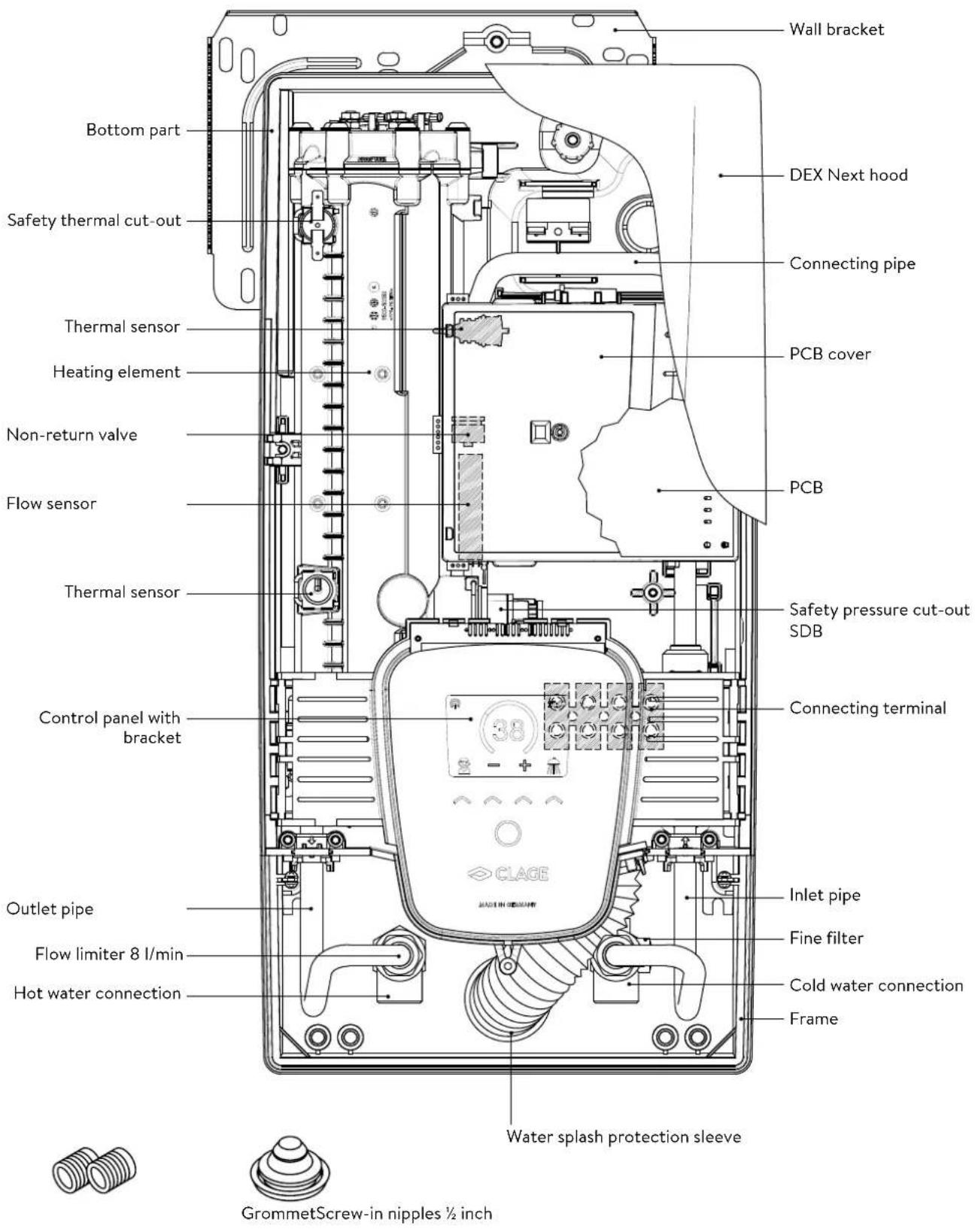
1. Overview
EN
text_image
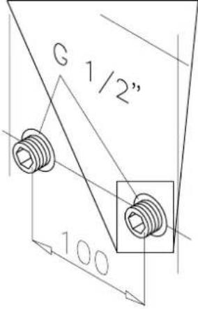
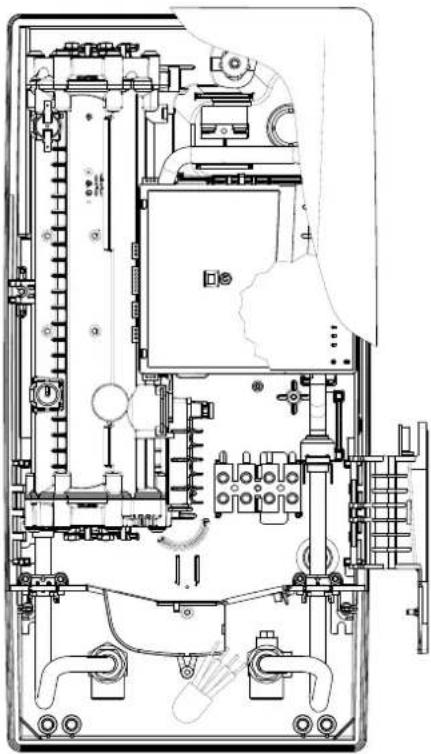
Wall bracket DEX Next hood Safety thermal cut-out Connecting pipe Thermal sensor PCB cover Heating element Non-return valve Flow sensor PCB Thermal sensor Safety pressure cut-out SDB Control panel with bracket Connecting terminal Outlet pipe Inlet pipe Flow limiter 8 l/min Fine filter Cold water connection Hot water connection Frame Water splash protection sleeve GrommetScrew-in nipples ½ inch2. Technical specifications
| Model DEX Next | ||||
| Energy efficiency class A * | ) | |||
| Rated capacity / rated current 18 kW..27 kW (26A..39A) | ||||
| Chosen capacity / current | 18 kW / 26A | 21 kW / 30A | 24 kW / 35A | 27 kW / 39A |
| Electrical connection | 3~/PE 380..415 V AC | 3~/PE 400 V AC | ||
| Min. required cable size1) | 4.0 mm2 | 4.0 mm2 | 6.0 mm2 | 6.0 mm2 |
| Hot water (l/min)max. at Δt = 28 Kmax. at Δt = 38 K | 9.22)6.8 | 10.72)7.9 | 12.32)9.02) | 13.82)10.22) |
| Rated volume 0.4 l | ||||
| Rated pressure 1.0 MPa (10 bar) | ||||
| Connecting type pressure-resistant / pressureless | ||||
| Heating system | Bare wire heating system IES® | |||
| @ 15°C:Required specific water resistanceSpecific electrical conductivity | ≥ 1100 Ωcm≤ 90 mS/m | |||
| Inlet temperature | ≤ 70°C | |||
| Flow rate to switch on - max. flow rate | 1.5 l/min - 8.03) | |||
| Pressure loss | 0.08 bar at 1.5 l/min 1.3 bar at 9.0 l/min4) | |||
| Temperature range | 20 - 60 °C | |||
| Water connection | G1⁄2 inch | |||
| Weight (when filled with water) | 4.2 kg | |||
| VDE class of protection | I | |||
| Type of protection / safety |   IP25 CE IP25 CE | |||
*) The declaration complies with the EU regulation No 812/2013.
1) Maximum applicable cable size is 10 mm^2 at electrical connection from above
2) Mixed water
3) Flow rate limited to achieve optimum temperature rise
4) Without flow regulator
3. Dimensions
text_image
170 468 363 56 100Dimensions in mm
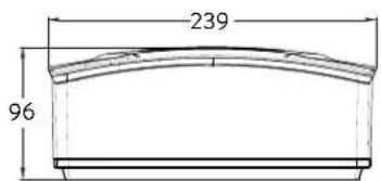
text_image
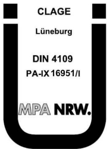
239 964. Installation

text_image
CLAGE Lüneburg DIN 4109 PA-IX 16951/I MPA NRW.Based on the national constitution guidelines a general test certificate concerning the evidence of applicability of noise behaviour is granted.
The following regulations must be observed:
• e.g. VDE 0100
• EN 806
- Installation must comply with all statutory regulations, as well as those of the local electricity and water supply companies.
• The rating plate and technical specifications
- Only intact and appropriate tools must be used
Installation site
- Appliance must only be installed in frost-free rooms. Never expose appliance to frost.
- The Appliance must be wall mounted and has to be installed with water connectors downward or alternative transversely with water connections left.
- The appliance complies with protection type IP25 and may therefore be installed in protection zone 1 according to VDE 0100 part 701 (IEC 60364-7).
- In order to avoid thermal losses, the distance between the instantaneous water heater and the tap connection should be as small as possible.
• The appliance must be accessible for maintenance work. - Plastic pipes may only be used if they conform to DIN 16893, Series 2.
- The specific resistance of the water must be at least 1100 Ω cm at 15 °C. The specific resistance can be asked for with your water distribution company.
natural_image
3D mechanical assembly diagram showing internal components and mounting holes (no text or symbols)
natural_image
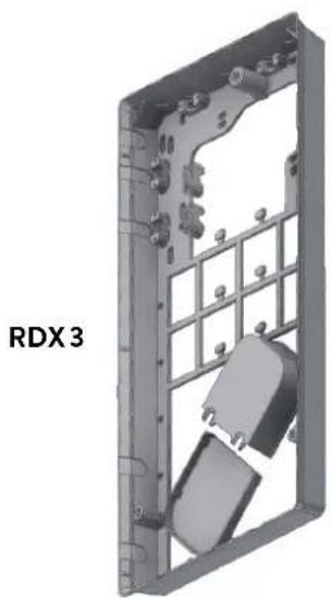
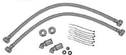
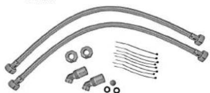
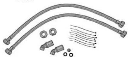
Technical illustration of VDX pipe fittings and connectors (no text or symbols)Mounting accessories
For installations under difficult conditions, these mounting accessories are available:
Mounting frame kit RDX3
(Art. no. 36100)
The instant water heater can be installed by means of this mounting kit in the below situations. The power supply cable is coming out of the wall at any place from behind the unit, but the wall has unusual surface conditions, making it difficult for installing the water heater.
When using the RDX the protection class changes from IP25 to IP24.
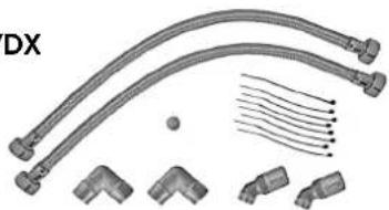
Extension kit VDX
(Art. no. 34120) - RDX / RDX 3 is necessary! -
The instant water heater can be installed by means of this extension kit if the water pipes are coming displaced or exchanged out of the wall or if they are coming edge-wise on the wall to the unit. The power supply could come out of the wall at any place under the unit or the wiring could be installed surface-mounted.

natural_image
Product diagram of UDX connectors and wiring components (no text or symbols)Extension kit UDX
(Art. no. 34110) - RDX / RDX 3 is necessary! -
The instant water heater can be installed by means of this extension kit if the water-connections are expiring above the unit. The power supply could come out of the wall at any place under the unit or the wiring could be installed surface-mounted.
4. Installation
text_image
12
text_image
G 1/2" 100Installing the wall bracket
Note: If you install this instantaneous water heater in exchange for a conventional instantaneous water heater, there is generally no need to drill holes for the wall bracket, in this case step 2 would not be necessary.
Thoroughly rinse the water supply pipes before installation to remove soiling from the pipes.
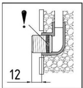
- Using a 12 mm hexagon socket screw key, screw the screw-in nipples into the wall connections. The seals must be fully screwed into the thread. After tightening, the double nipples must protrude by 12 - 14 mm.
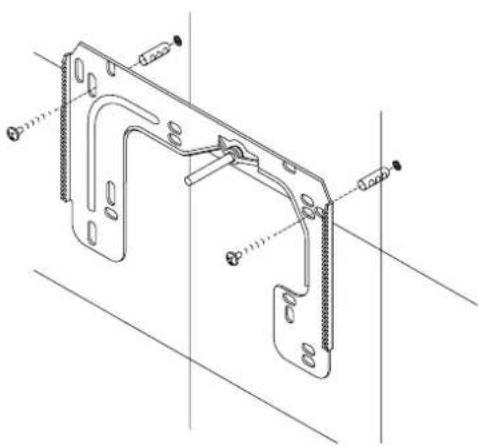
- Hold the included mounting template on the wall and align it so that the holes in the template fit over the double nipples. Mark the drill holes according to the template and drill them using a 6 mm drill. Insert the included dowels.
- Pull down the faceplate and unscrew the main hood screw to open the appliance.
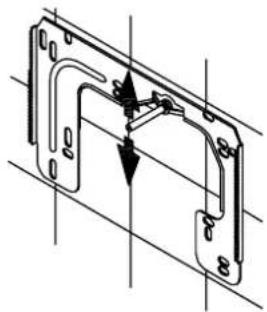
- Loosen the knurled nut to remove the wall bracket and screw the wall bracket to the wall. Offset tiling or uneven surfaces can be compensated by up to 30 mm with the aid of the spacers supplied. The spacers are fitted between the wall and the wall bracket.
natural_image
Technical line drawing of a mechanical bracket assembly (no text or symbols)
text_image
warm cold DInstalling connection pieces
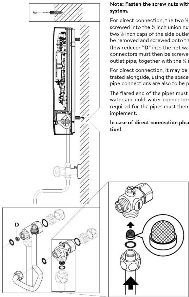
Note: Fasten the screw nuts with caution, to avoid damage to the valves or the piping system.
- As shown in the illustration, screw the cold water connection piece with the union nut and the 12 inch seal onto the cold water connection.
- Screw the hot water connection piece with the union nut and the 12 inch seal onto the hot water connection.
- Put the water flow reducer "D" into the hot water connection piece.
4. Installation

natural_image
Technical line drawing of a mechanical assembly with no visible text or symbolsInstalling the appliance
- The electrical power supply cable may be connected in the upper part or is surface mounted. Only in such case, first follow the steps one through three according to the description "Electrical connection from above" in chapter "Electrical connection".
- Place the appliance on the heater bracket so that the threaded rod of the wall bracket fits in the corresponding hole of the appliance. If necessary, slight corrections are possible by carefully bending the threaded rod of the wall bracket. However, it must be possible to screw on the water connection pipes of the appliance without applying force.
- Screw the plastic knurled nut onto the threaded rod of the wall bracket.
- Screw the two 18 inch union nuts of the appliance's water connection pipes, each with the 38 inch seal, onto the fittings.
natural_image
Technical line drawing of a mechanical bracket assembly (no text or symbols)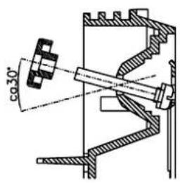
text_image
co 30°
text_image
co 30°
text_image
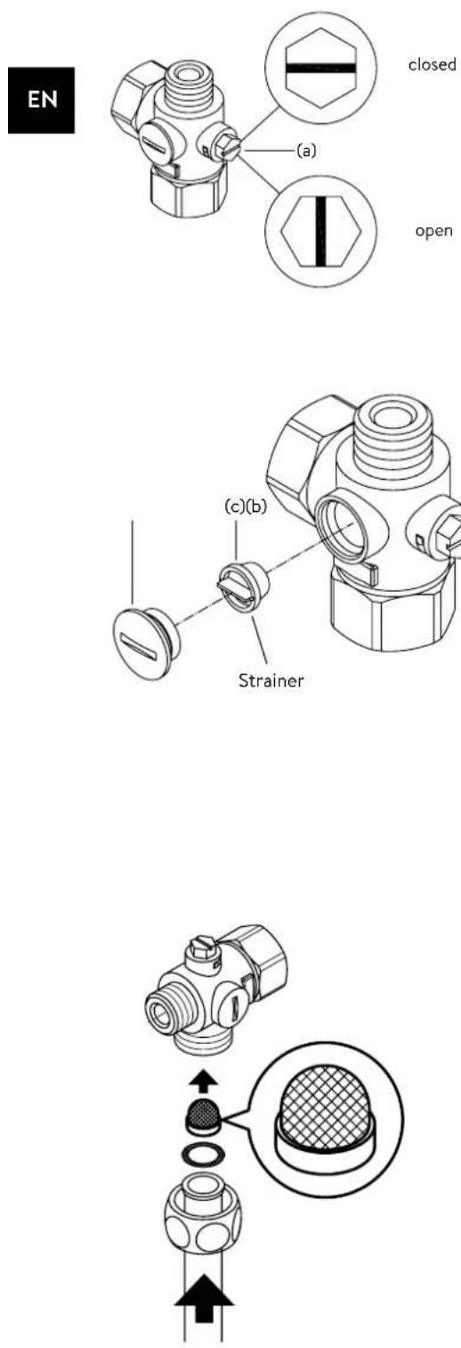
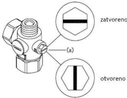
(a) closed open- Open the water supply line to the unit and slowly open (position "open") the shut-off valve (a) in the cold water connection piece. Check all connections for leaks.
- Next, open and close the hot water tapping valve several times until no more air emerges from the line and all air has been eliminated from the instantaneous water heater.
5. Direct connection
text_image
Note: Fasten the screw nuts with system. For direct connection, the two ½ screwed into the ½ inch union nut two ½ inch caps of the side outlet be removed and screwed onto the flow reducer "D" into the hot wat connectors must then be screwed outlet pipe, together with the ¾ in For direct connection, it may be a trated alongside, using the spacer pipe connections are also to be pi The flared end of the pipes must water and cold-water connectors required for the pipes must then implement. In case of direct connection plea- tion!Note: Fasten the screw nuts with caution, to avoid damage to the valves or the piping system.
For direct connection, the two 12 inch screw-in nipples and the 12 inch seals must be screwed into the 12 inch union nuts of the hot-water and cold-water connectors. The two 12 inch caps of the side outlets of the hot-water and cold-water connectors must be removed and screwed onto the open end of the screw-in nipples. Put the water flow reducer “D” into the hot water connection piece. The hot-water and cold-water connectors must then be screwed into the 38 inch union nut of the appliance inlet and outlet pipe, together with the 38 inch seals.
For direct connection, it may be advisable to mount the appliance at a distance as illustrated alongside, using the spacer sleeves supplied. The two fixing holes near the lower pipe connections are also to be professionally fixed with 6 mm dowels and screws.
The flared end of the pipes must be screwed into the 12 inch side outlets of the hot-water and cold-water connectors with 12 inch union nuts and 12 inch seals. The holes required for the pipes must then be opened of the housing with the aid of a blunt implement.
In case of direct connection please note: Put the strainer into the cold water connection!
6. Electrical connection
Wiring diagram
text_image
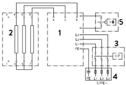
2 4 B 8 A C 1 L3 L2 L1 PE 3/PE~ 4 5 3 P- Electronic circuitry
- Heating element
- Safety pressure cut-out
- Connecting terminal
- Safety thermal cut-out
Only by a specialist!
Please observe:
• e.g. VDE 0100
- The installation must comply with current IEC and national local regulations or any particular regulations, specified by the local electricity supply company
• The rating plate and technical specifications
• The appliance must be earthed!
Structural prerequisites
- The appliance must be installed via a permanent connection. Heater must be earthed!
- The electric wiring should not be injured. After mounting, the wiring must not be direct accessible.
- An all-pole disconnecting device (e.g. via fuses) with a contact opening width of at least 3 mm per pole should be provided at the installation end.
- To protect the appliance, a fuse element must be fitted with a tripping current commensurate with the nominal current of the appliance.
Load shedding relay
If further three-phase appliances are connected, a load shedding relay designed for electronic instantaneous water heaters (CLAGE no. 82250) can be connected to phase conductor L2.
To change the operating mode, after making the electrical connection and the initial operation call up the settings menu. Then select the point "Load shedding".
Select "OK" to access the edit mode. To set a value of "0", "1" or "2" press and hold ▲ or ▼ for two seconds. By plugging the jumper in accordance with the locking function (see chapter »7. Initial operation« section »Locking function«) the load shedding is activated.
| Value | Description |
| 0 | Operation without load shedding relay, factory setting |
| 1 | Operation with normal load shedding relay |
| 2 | Operation with sensitive load shedding relay |
Operating mode 1 must be selected first, thus to check the correct operation of the load shedding relay at low appliance output (35 degree celsius setpoint and low water flow rate). Mode "2" must be selected if the load shedding relay flickers.
6. Electrical connection


text_image
Technical diagram showing mechanical assembly with labeled components and directional arrowsElectrical connection from below
Note: If necessary, the connecting terminal can be displaced to the upper part of the appliance. If you want to do so, please follow the instructions in the next chapter.
Check that the power supply is switched off prior to electrical connection!
- Dismantle approximately 6 cm off the connecting cable above the wall outlet. With the smaller opening ahead, slide the water splash protection sleeve over the connecting cable so that the sleeve is flush with the wall. This prevents any leaking water from coming into contact with the electrical leads. It must not become damaged! The protection sleeve must be used!
- Open the control panel holder rightwards.
- Strip the cables and plug them in the connecting terminals according to the wiring diagram. The appliance must be earthed.
- Pull the protective sleeve over the connecting cables until the sleeve fits perfectly in the recess of the intermediate panel. Adjust the water splash protection sleeve as illustrated and fix it with the sleeve fixing (A). Reinsert the control panel holder and lock it on.
- Place the hood on the appliance and screw in the fastening screw. After that you can slide on the faceplate from the bottom up to the stop.
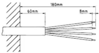
text_image
180mm 60mm 8mm

natural_image
Technical diagram of an electrical enclosure with wiring and components (no readable text or symbols)Electrical connection from above
Check that the power supply is switched off prior to electrical connection!
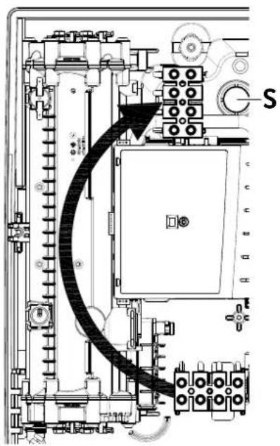
- Open the prepared breaking point (S) in the upper part of the appliance by pressing with a blunt implement (e.g. srewdriver). For surface-mounted connection cable additional open the breakout at the right side of the bottom part.
- Slit the grommet of the accessory set to match the cable size. The opening in the grommet should be slightly smaller than the cross-section of the cable in order to ensure optimum protection against water. Fit the grommet into the opening. The protection grommet must be used!
- Strip the connection cable so that the sheath extends through the grommet into the appliance. Hold the prepared appliance so that you can route the cable into the grommet with the other hand.
- Place the appliance on the wall bracket so that the threaded rod of the wall bracket fits in the corresponding hole of the appliance.
- Open the control panel.
- Unscrew the fastening screw of the connecting terminal. Displace the connecting terminal to the upper foot. Affix the connecting terminal again.
- Strip the individual wires and plug them in the connecting terminals according to the wiring diagram. The appliance must be earthed.
- Reinsert the control panel and lock it on.
- Place the hood on the appliance and screw in the fastening screw. After that you can slide on the faceplate from the bottom up to the stop.
Note: To ensure IP25 protection class, please don't remove the bottom water splash protection sleeve.
7. Initial operation

text_image
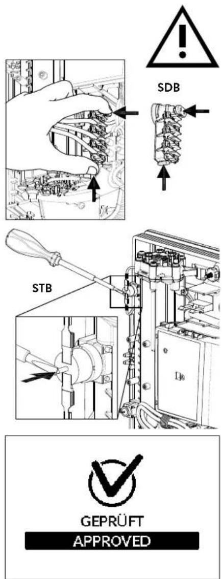
SDB STB GEPRÜFT APPROVEDMultiple Power System MPS®:
The rated capacity (max. power consumption) is 27 kW / 400 V and can be changed internally to 24 kW, 21 kW or 18 kW.

text_image
Technical diagram showing a disassembled electronic device with labeled parts and a tool inserted into it.Before making the electrical connection, fill the mains and the appliance with water by carefully opening and closing the hot water tap in order to vent completely.
To ensure a maximum flow, remove any existing aerator from the faucet. Flush the warm and cold water pipes each at least for one minute.
After every draining (e.g. after work on the plumbing system or following repairs to the appliance), the heater must be re-vented in this way before starting it up again.
If the water heater cannot be put into operation, the temperature cut-out or the pressure cut-out may have tripped during transport. Check that the power supply is switched off and reset the cut-out, if necessary.
Selection of power rating
Only by authorised specialist, otherwise lapse of guarantee!
On delivery, the display shows the screen "APPROVED" (see left). If not, the device has already been powered once. In this case, please follow the section "Reinstallation".
Upon first connection of the appliance to the supply voltage, select the maximum power rating. Only after having set the power rating, the heater provides its standard operation mode.
The maximum allowable power rating at installation site depends on the local situation. It is imperative to observe all data shown in the table "Technical specifications", in particular the required cable size and fuse protection for the electrical connection. Moreover, the electrical installation must comply with the statutory regulations of the respective country and those of the local electricity supply company (Germany: DIN VDE 0100).
- Switch on the power supply to the appliance.
- When switching on the supply voltage for the first time, the display shows the menu to select the language. Choose your language, after that the selection of power rating appears.
- Select the maximum allowable power rating depending on the local situation via sensor keys (18, 21, 24 or 27 kW).
- Select "OK" to confirm the setting.
- Mark the set power rating on the rating plate.
- After having set the maximum allowable power rating, the heating element will be activated after approx. 10 - 30 sec of continuous water flow.
- Open the hot water tap. Check the function of the appliance.
- Explain the user how the instantaneous water heater works and hand over the operating instructions.
- Fill in the guarantee registration card and send it to the CLAGE After-Sales Service or use the online registration on our website (see also page 22).
Reinstallation
In case the appliance will be commis sioned again under different installation conditions than during its initial operation, it may be necessary to adapt the maximum power rating.
A temporary short-circuit of the two pins, e.g. with a screwdriver acc. to EN 60900 (see figure), will reset all heater parameters to works setting and lock the heating. The display shows the menu to select the language. Choose your language, after that the selection of power rating appears. This condition will maintain when activating and deactivating the supply voltage.
7. Initial operation
Shower application
The water heater's temperature must be limited to 55 °C, if it is connected to a shower. The temperature limit must be set to a value less or equal 55 °C in the setting menu, in consultation with the customer and the lock level must be activated.
When the appliance is operated with preheated water, it must be ensured that this temperature is limited to 55 °C as well.
text_image
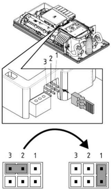
Technical diagram showing internal components of an electronic device with numbered parts and a schematic arrow indicating assembly or connection.Pos. OFF Pos. 1
Locking function
The operating mode of the appliance can be restricted.
Activation of the locking function
- Select required parameters via the setting menu (see online user manual chapter "Settings", subpoints "Temperature limit" and / or "Load shedding").
- Disconnect the appliance from the power supply (e.g. by switching off the fuses).
- Take the jumper off the power electronics and change to position "1" (see picture).
- Put the appliance into operation again.
Deactivation of the locking function
- Disconnect the appliance from the power supply (e.g. by switching off the fuses).
- Take the jumper off the power electronics and change to position "OFF" (see picture).
- Put the appliance into operation again.
8. Maintenance work
Maintenance work must only be conducted by an authorised professional.
Cleaning and replacing the filter strainer
The cold water connection of this instantaneous water heater is equipped with an integrated shut-off valve and a strainer. Soiling of the strainer may reduce the warm water output. Clean or replace the strainer as follows:
- De-energize the instantaneous water heater (e.g. via deactivating the fuses) and prevent inadvertent reactivation of them.
- To open the appliance, take off the small face plate, loose the screw behind this cover and detach the hood.
- Close the shut-off valve (a) in the cold water connection piece (position "closed").
- Unscrew the screw plug (b) from the cold water connection piece and take out the strainer (c). Note: Residual water can leak
- The strainer can now be cleaned or replaced.
- After fitting of the clean strainer tighten the screw plug.
- Slowly reopen the shut-off valve in the cold water connection piece (position "open"). Check all connections for leaks.
- Vent the appliance by carefully opening and closing the affiliated warm water tap valve several times until air no longer emerges from the pipe.
- Fit the hood of the appliance. Then switch on the power again (e.g. via activating the fuses).
Cleaning and replacing the filter strainer if direct connected
The cold water connection of this instantaneous water heater is equipped with a strainer. Soiling of the strainer may reduce the warm water output. Clean or replace the strainer as follows:
- De-energize the instantaneous water heater (e.g. via deactivating the fuses) and prevent inadvertent reactivation of them.
- Close the shut-off valve in the mains water supply of the instantaneous water heater.
- To open the appliance, take off the small face plate, loose the screw behind this cover and detach the hood.
- Unscrew mains water inlet from connection piece and take out the strainer. Note: Residual water can leak
- The strainer can now be cleaned or replaced.
- After refitting the clean strainer reconnect the mains water inlet to the connection piece.
- Slowly reopen the shut-off valve in the mains water supply. Check all connections for leaks.
- Vent the appliance by carefully opening and closing the affiliated warm water tap valve several times until air no longer emerges from the pipe.
- Fit the hood of the appliance. Then switch on the power again (e.g. via activating the fuses).
Sommaire
natural_image
White industrial water heater with digital display showing 38°C and control buttons (no text or symbols on main body)natural_image
Symbol of a trash bin crossed out by two diagonal lines (no text or numbers present)natural_image
Simple black-and-white line drawing of a tree with two horizontal lines underneath (no text or symbols)text_image
Warning symbol with exclamation mark inside trianglenatural_image
3D mechanical assembly diagram showing internal components and mounting holes (no text or symbols)
natural_image
Technical illustration of VDX pipe fittings and connectors (no text or symbols)
natural_image
Product assembly of UDX connectors and wiring (no text or symbols visible)natural_image
Technical line drawing of a mechanical bracket assembly (no text or symbols)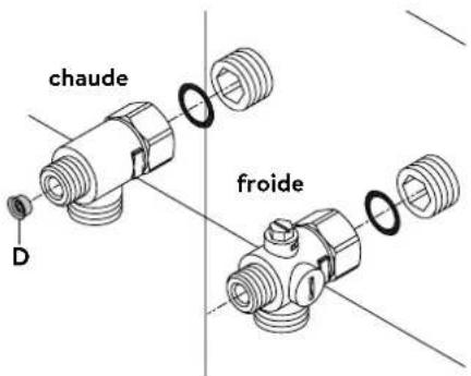
text_image
chaude D froidePose des raccords
natural_image
Technical line drawing of a mechanical assembly with no visible text or symbolsnatural_image
Technical line drawing of a mechanical bracket assembly with no visible text or symbols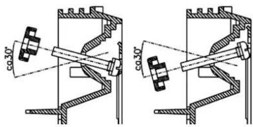
text_image
co30' co35'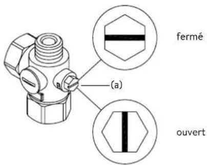
text_image
180mm 60mm 8mm

natural_image
Technical diagram of an electrical enclosure with wiring and components, no readable text or symbolstext_image
GEPRÜFT APPROVED
Multiple Power System
text_image
Technical diagram showing a disassembled electronic device with labeled parts and a tool inserted into it.Remise en service
text_image
Technical diagram of an electronic device with labeled components and internal wiring, showing exploded and assembled views.Fonction de blocage
text_image
Technical diagram showing a mechanical component with a close-up view of its cross-section, likely illustrating a mechanical assembly or assembly process.https://partner.clage.com/en/service/device-registration/

Instructies
natural_image
White industrial water heater with digital display showing 38% and control buttons (no text or symbols on main body)natural_image
Symbol of a trash bin crossed out by two diagonal lines (no text or numbers present)text_image
Statistics User Settings Info OK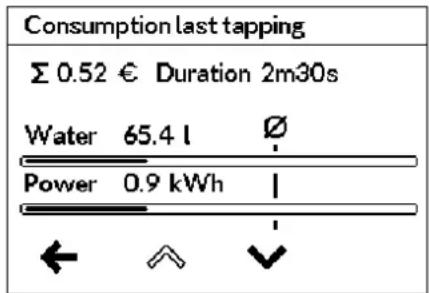
text_image
Consumption last tapping Σ 0.52 € Duration 2m30s Water 65.4 l Ø Power 0.9 kWh | ← ↑ ↓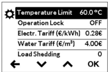
text_image
Temperature Limit 60.0°C Operation Lock OFF Electr. Tariff (€/kWh) 0.28€ Water Tariff (€/m³) 4.00€ Load Shedding 0 ← ↙ ↑ OKNote: If the instantaneous water heater supplies a shower, then the maximum temperature was limited during the installation of the appliance and can not be changed.
3. Gebruik
text_image
Enter PIN 08 00 ← ↑ ↓ →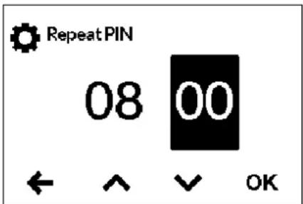
text_image
RepeatPIN 08 00 ← ↑ ↓ OK| Value | Description |
| 0 | Operation without load shedding relay, factory setting |
| 1 | Operation with normal load shedding relay |
| 2 | Operation with sensitive load shedding relay |
3. Gebruik
text_image
User 1 User 2 User 3 User 4 OK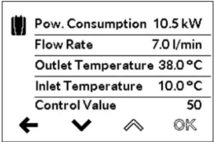
text_image
Pow. Consumption 10.5 kW Flow Rate 7.0 l/min Outlet Temperature 38.0 °C Inlet Temperature 10.0 °C Control Value 50 ← √ ↑ OKGebruiker "User"
natural_image
Simple line drawing of a tree with two roots and a cloud-like shape at the top (no text or symbols)text_image
Warning symbol with exclamation mark inside trianglenatural_image
3D mechanical assembly diagram showing internal components and mounting holes (no text or symbols)
natural_image
Technical illustration of VDX connectors and terminal blocks (no text or symbols)UDX
natural_image
Product assembly of flexible hose connectors and connectors (no text or symbols visible)natural_image
Technical line drawing of a mechanical bracket assembly (no text or symbols)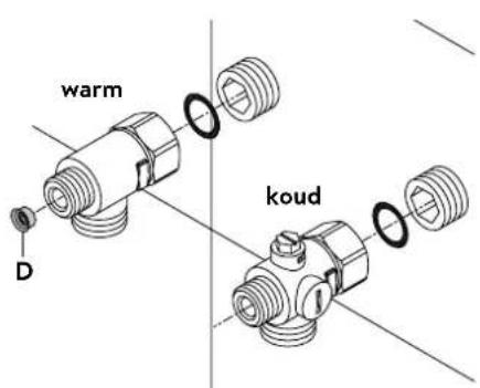
text_image
warm koud Dnatural_image
Technical line drawing of a mechanical assembly with no visible text or symbolsApparaat monteren
natural_image
Technical line drawing of a mechanical bracket assembly with no visible text or symbols
text_image
co30°
text_image
co 30°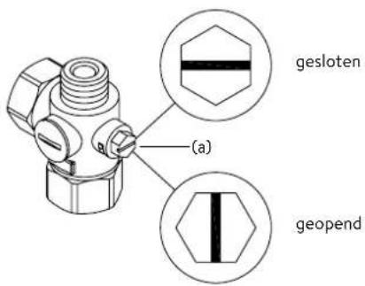
text_image
(a) gesloten geopend| Value | Description |
| 0 | Operation without load shedding relay, factory setting |
| 1 | Operation with normal load shedding relay |
| 2 | Operation with sensitive load shedding relay |
text_image
180mm 60mm 8mm

text_image
Technical diagram of an electrical enclosure with labeled components and a curved black line indicating flow or connection.text_image
GEPRÜFT APPROVED
Multiple Power System MPS®:
text_image
Technical diagram showing a disassembled electronic device with labeled parts and a tool inserted into it.text_image
Technical diagram of an electronic device with labeled components and internal wiring, showing exploded and assembled views.text_image
Technical diagram showing a mechanical component with an inset close-up of a textured surface, illustrating assembly or assembly process.https://partner.clage.com/en/service/device-registration/

natural_image
White industrial water heater with digital display showing 38% and control buttons (no text or symbols beyond branding)natural_image
Symbol of a trash bin crossed out by two diagonal lines (no text or numbers present)text_image
Statistics User Settings Info OK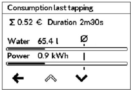
text_image
Consumption last tapping Σ 0.52 € Duration 2m30s Water 65.4 l Ø Power 0.9 kWh | ← ↗ ↓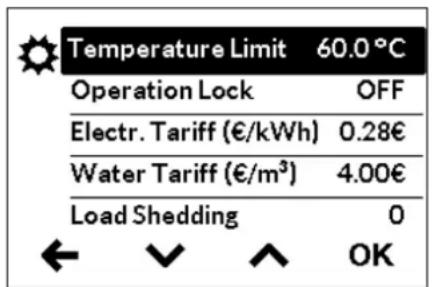
text_image
Temperature Limit 60.0°C Operation Lock OFF Electr. Tariff (€/kWh) 0.28€ Water Tariff (€/m³) 4.00€ Load Shedding 0 ← ↙ ↑ OKtext_image
Enter PIN 08 00 ← ^ √ →
text_image
RepeatPIN 08 00 ← ^ ↓ OKtext_image
User 1 User 2 User 3 User 4 OK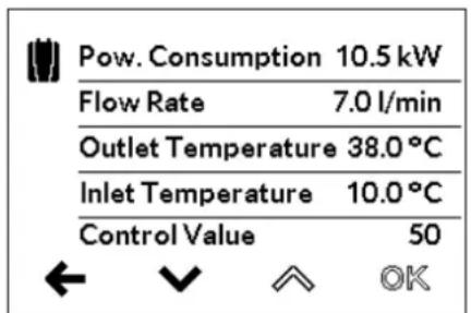
text_image
Pow. Consumption 10.5 kW Flow Rate 7.0 l/min Outlet Temperature 38.0 °C Inlet Temperature 10.0 °C Control Value 50 ← √ ↑ OKUtilizador "User"
natural_image
Simple line drawing of a tree with two roots and a cloud-like shape at the top (no text or symbols)text_image
Warning symbol with exclamation mark inside trianglenatural_image
3D mechanical assembly diagram showing internal components and mounting holes (no text or symbols)
natural_image
Product diagram of VDX connectors with multiple tubes and connectors (no text or symbols)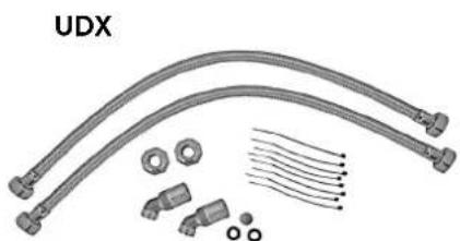
natural_image
Product assembly of UDX connectors and wiring (no text or symbols visible)A ter em conta:
• p. ex. VDE 0100
• EN 806
natural_image
Technical line drawing of a mechanical bracket assembly (no text or symbols)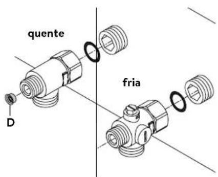
text_image
quente D frianatural_image
Technical line drawing of a mechanical assembly with no visible text or symbolsnatural_image
Technical line drawing of a mechanical bracket assembly (no text or symbols)
text_image
co 30°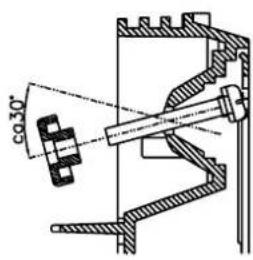
text_image
co 30°
text_image
fechado (a) abertotext_image
180mm 60mm 8mm
text_image
Technical diagram of an electrical or mechanical device with labeled component 'S' and a curved arrow indicating flow or direction.text_image
GEPRÜFT APPROVED
Multiple Power System MPS®:
text_image
Technical diagram showing a device with labeled parts and a tool inserted, including numbered annotations 1, 2, and 3.Ligar novamente
text_image
Technical diagram of an electronic device with labeled components and internal wiring, showing exploded and assembled views.Bloqueio
text_image
Technical diagram showing a mechanical component with an inset close-up of a textured surface, illustrating assembly or assembly process.https://partner.clage.com/en/service/device-registration/

natural_image
White industrial water heater with digital display showing 38°C and control buttons (no text or symbols on main body)natural_image
Symbol of a trash bin crossed out by two diagonal lines (no text or numbers present)text_image
Statistics User Settings Info OK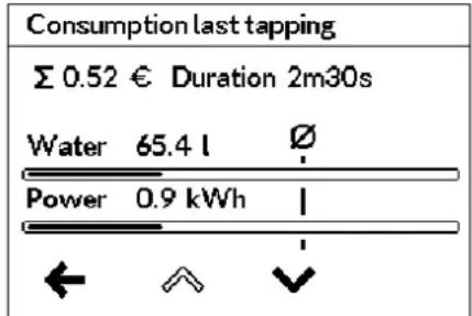
text_image
Consumption last tapping Σ 0.52 € Duration 2m30s Water 65.4 l Ø Power 0.9 kWh | ← ↑ ↓text_image
Enter PIN 08 00 ← ^ √ →
text_image
RepeatPIN 08 00 ← ↑ ↓ OKtext_image
User 1 User 2 User 3 User 4 OKUsuario
text_image
Pow. Consumption 10.5 kW Flow Rate 7.0 l/min Outlet Temperature 38.0 °C Inlet Temperature 10.0 °C Control Value 50 ← √ ↑ OKnatural_image
Simple black-and-white line drawing of a tree with two horizontal lines underneath (no text or symbols)text_image
Warning symbol with exclamation mark inside trianglenatural_image
3D CAD model of a mechanical housing or enclosure with internal grid structure and mounting holes (no text or symbols visible)
natural_image
Pure electrical circuit lines without any symbols
natural_image
Product diagram of UDX cable connectors and connector parts (no text or symbols)natural_image
Technical line drawing of a mechanical bracket assembly (no text or symbols)natural_image
Technical line drawing of a mechanical assembly with no visible text or symbolsMontar el equipo
natural_image
Technical line drawing of a mechanical component with internal structure and directional arrows (no text or symbols)
text_image
co30°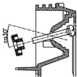
text_image
co 30°
text_image
(a) closed opentext_image
Technical diagram showing mechanical assembly with labeled components and directional arrows, likely illustrating a fluid or cooling system.text_image
180mm 60mm 8mm
natural_image
Technical diagram of an electrical or mechanical assembly with labeled component 'S' (no readable text or symbols beyond label)text_image
GEPRÜFT APPROVEDMultiple Power System MPS®:
text_image
Technical diagram showing a disassembled electronic device with labeled parts and a tool inserted into it.text_image
(c)(b) Tamiz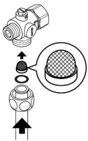
text_image
Technical diagram showing a mechanical component with cross-sectional view and directional arrows indicating assembly or assembly process.natural_image
White industrial water heater with digital display showing 38°C and control buttons (no text or symbols on main body)natural_image
Symbol of a trash bin crossed out by two diagonal lines (no text or numbers present)text_image
Statistics User Settings Info OK
text_image
Consumption last tapping Σ 0.52 € Duration 2m30s Water 65.4 l Ø Power 0.9 kWh | ← ↑ ↓
text_image
Temperature Limit 60.0°C Operation Lock OFF Electr. Tariff (€/kWh) 0.28€ Water Tariff (€/m³) 4.00€ Load Shedding 0 ← ↙ ↑ OKtext_image
Enter PIN 08 00 ← ↑ ↓ →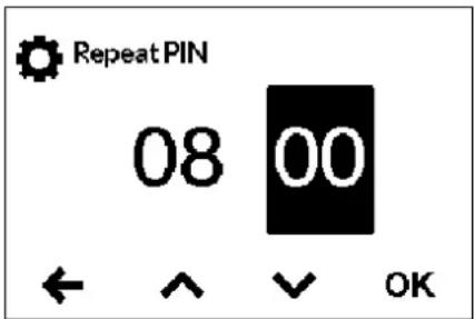
text_image
RepeatPIN 08 00 ← ^ ✓ OKtext_image
User 1 User 2 User 3 User 4 OK
text_image
Pow. Consumption 10.5 kW Flow Rate 7.0 l/min Outlet Temperature 38.0 °C Inlet Temperature 10.0 °C Control Value 50 ← √ ↑ OKUżytkownik „User”
natural_image
Simple black-and-white line drawing of a tree with two horizontal lines below (no text or symbols)text_image
Warning symbol with exclamation mark inside trianglenatural_image
3D mechanical assembly diagram showing internal components and mounting holes (no text or symbols)
natural_image
Technical illustration of VDX connectors and wiring components (no text or symbols)UDX
natural_image
Product assembly of flexible hose connectors and connectors (no text or symbols visible)natural_image
Technical line drawing of a mechanical bracket assembly (no text or symbols)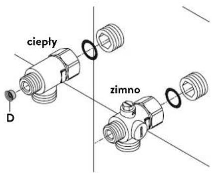
text_image
cieply D zimnonatural_image
Technical line drawing of a mechanical assembly with no visible text or symbolsMontaż urządzenia
natural_image
Technical line drawing of a mechanical bracket assembly (no text or symbols)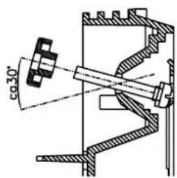
text_image
co30°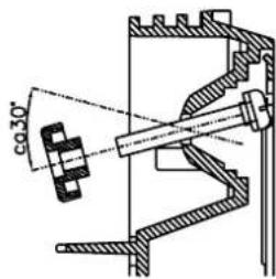
text_image
co 30°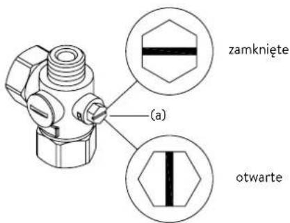
text_image
zamkniete (a) otwartetext_image
Technical diagram showing mechanical assembly with labeled components and directional arrowstext_image
180mm 60mm 8mm

text_image
Technical diagram of an electrical or mechanical device with labeled component 'S' and internal wiring connectionstext_image
GEPRÜFT APPROVEDMultiple Power System MPS®:
text_image
Technical diagram showing a disassembled electronic device with labeled parts and a tool interacting with it.text_image
Technical diagram of an electronic device with labeled components and internal wiring, showing exploded and assembled views.Funkcja blokady
text_image
Technical diagram showing mechanical assembly with labeled components and a magnified inset of a textured componenthttps://partner.clage.com/en/service/device-registration/

natural_image
White industrial water heater with digital display showing 38°C and control buttons (no text or symbols on main body)natural_image
Symbol of a trash bin crossed out by two diagonal lines (no text or numbers present)text_image
Statistics User Settings Info OK
text_image
Consumption last tapping Σ 0.52 € Duration 2m30s Water 65.4 l Ø Power 0.9 kWh | ← ↑ ↓Главное меню
text_image
Enter PIN 08 00 ← ^ √ →
text_image
RepeatPIN 08 00 ← ^ ✓ OK
text_image
User 1 User 2 User 3 User 4 OK

text_image
Pow. Consumption 10.5 kW Flow Rate 7.0 l/min Outlet Temperature 38.0 °C Inlet Temperature 10.0 °C Control Value 50 ← √ ↑ OKПользователь "User"
natural_image
Simple black-and-white line drawing of a tree with two horizontal lines below (no text or symbols)text_image
Warning symbol with exclamation mark inside trianglenatural_image
3D mechanical assembly diagram showing internal components and mounting holes (no text or symbols)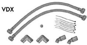
natural_image
Technical illustration of VDX pipe fittings and connectors (no text or symbols)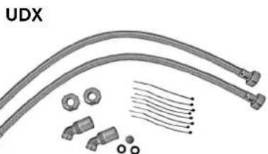
natural_image
Product assembly diagram showing UDX connectors, bolts, and connector parts (no text or symbols)natural_image
Technical line drawing of a mechanical bracket assembly (no text or symbols)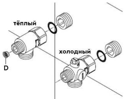
natural_image
Technical line drawing of a mechanical assembly with no visible text or symbolsМонтаж нагревателя
natural_image
Technical line drawing of a mechanical bracket assembly (no text or symbols)
text_image
co 30°
text_image
co 30°
text_image
180mm 60mm 8mm

text_image
Technical diagram of an electrical enclosure with labeled components and a curved black line indicating a connection or path.text_image
GEPRÜFT APPROVEDMultiple Power System MPS®:
text_image
Technical diagram showing a disassembled electronic device with labeled parts and a tool inserted into it.text_image
Technical diagram showing a mechanical component with cross-sectional view and assembly instructionshttps://partner.clage.com/en/service/device-registration/

Návod k obsluze
natural_image
White industrial water heater with digital display showing 38°C and control buttons (no text or symbols on main body)natural_image
Symbol of a trash bin crossed out by two diagonal lines (no text or numbers present)text_image
Statistics User Settings Info OK
text_image
Consumption last tapping Σ 0.52 € Duration 2m30s Water 65.4 l Ø Power 0.9 kWh | ← ↑ ↓text_image
Enter PIN 08 00 ← ^ ↓ →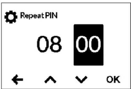
text_image
RepeatPIN 08 00 ← ↑ ✓ OKtext_image
User 1 User 2 User 3 User 4 OKUživatel »User«
text_image
Pow. Consumption 10.5 kW Flow Rate 7.0 l/min Outlet Temperature 38.0 °C Inlet Temperature 10.0 °C Control Value 50 ← √ ↑ OKnatural_image
Simple black-and-white line drawing of a tree with two roots and a cloud at the top (no text or symbols)text_image
Warning symbol with exclamation mark inside trianglenatural_image
3D mechanical assembly diagram showing internal components and mounting holes (no text or symbols)
natural_image
Product diagram of VDX connectors with multiple tubes and connectors (no text or symbols)UDX

natural_image
Product assembly of flexible hose connectors and connectors (no text or symbols visible)Dodržujte:
natural_image
Technical line drawing of a mechanical bracket assembly (no text or symbols)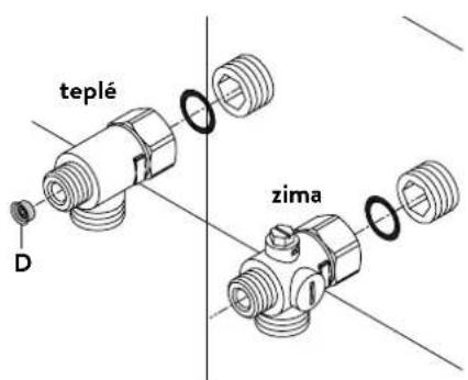
text_image
teplé D zimanatural_image
Technical line drawing of a mechanical assembly with no visible text or symbolsMontáž prístroje
natural_image
Technical line drawing of a mechanical bracket assembly (no text or symbols)
text_image
co 30°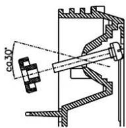
text_image
co 30°text_image
Technical diagram showing mechanical assembly with labeled components and directional arrowstext_image
180mm 60mm 8mm

text_image
Technical diagram of an electrical enclosure with labeled component 'S' and directional arrow indicating flow or movement.text_image
GEPRÜFT APPROVEDMultiple Power System MPS®:
text_image
Technical diagram showing a disassembled electronic device with labeled parts and a tool inserted into it.text_image
Technical diagram showing a mechanical component with an inset close-up of a textured surface, illustrating assembly or assembly process.https://partner.clage.com/en/service/device-registration/

Návod na použitie
natural_image
White industrial water heater with digital display showing 38% and control buttons (no text or symbols on main body)natural_image
Symbol of a trash bin crossed out by two diagonal lines (no text or numbers present)text_image
Statistics User Settings Info OK
text_image
Consumption last tapping Σ 0.52 € Duration 2m30s Water 65.4 l Ø Power 0.9 kWh | ← ↗ ↓text_image
Enter PIN 08 00 ← ^ √ →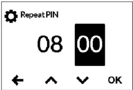
text_image
RepeatPIN 08 00 ← ^ ✓ OK- Settings: Automaticky aktívne, akonáhle sa vygeneruje PIN. Používatelía sa do menu s nastaveniami dostanú len s pomocou PIN.
- All: Na ovládanie zariadenia je potrebné zadanie kódu PIN.
- OFF: PIN sa vymaže a zariadenie je možné volne ovládat.
text_image
User 1 User 2 User 3 User 4 OK
text_image
Pow. Consumption 10.5 kW Flow Rate 7.0 l/min Outlet Temperature 38.0 °C Inlet Temperature 10.0 °C Control Value 50 ← √ ↑ OKPoužívatel' »User«
natural_image
Simple black-and-white line drawing of a tree with two horizontal lines below (no text or symbols)Ako ušetrit'energiu
text_image
Warning symbol with exclamation mark inside trianglenatural_image
3D mechanical assembly diagram showing internal components and mounting holes (no text or symbols)
natural_image
Product diagram of VDX connectors and wiring (no text or symbols)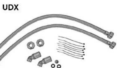
natural_image
Product diagram of UDX connectors and wiring components (no text or symbols)Príslušenstvo k montáži
natural_image
Technical line drawing of a mechanical bracket assembly (no text or symbols)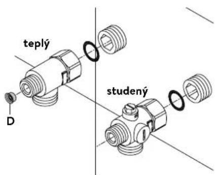
natural_image
Technical line drawing of a mechanical or electrical assembly with no visible text, numbers, or symbols.Namontovanie zariadenia
natural_image
Technical line drawing of a mechanical bracket assembly with no visible text or symbols
text_image
co.30°
text_image
φ30°text_image
Technical diagram showing mechanical assembly with labeled components and directional arrows, likely illustrating a gear or valve mechanism.text_image
180mm 60mm 8mm

text_image
Technical diagram of an electrical or mechanical device with labeled component 'S' and a curved black line indicating flow or connection.text_image
GEPRÜFT APPROVEDMultiple Power System MPS®:
text_image
Technical diagram showing a disassembled electronic device with labeled parts and a close-up of its internal structure.text_image
Technical diagram of an electronic device with labeled components and a schematic showing pin layout and connection arrows.Poz. VYP Poz. 1
Blokovacia funkcia
text_image
(c)(b) Sito
text_image
Technical diagram showing a mechanical component with cross-sectional view and directional arrows indicating assembly or assembly process.https://partner.clage.com/en/service/device-registration/

natural_image
White industrial water heater with digital display showing 38% and control buttons (no text or symbols beyond branding)natural_image
Symbol of a trash bin crossed out by two diagonal lines (no text or numbers present)text_image
Statistics User Settings Info OK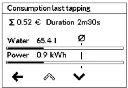
text_image
Consumption last tapping Σ 0.52 € Duration 2m30s Water 65.4 l Ø Power 0.9 kWh | ← ↗ ↓text_image
Enter PIN 08 00 ← ^ √ →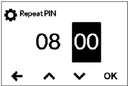
text_image
RepeatPIN 08 00 ← ^ ✓ OKtext_image
User 1 User 2 User 3 User 4 OKПотребител „User“
text_image
Pow. Consumption 10.5 kW Flow Rate 7.0 l/min Outlet Temperature 38.0 °C Inlet Temperature 10.0 °C Control Value 50 ← √ ↑ OKnatural_image
Simple black-and-white line drawing of a tree with two horizontal lines below (no text or symbols)text_image
Warning symbol with exclamation mark inside trianglenatural_image
3D mechanical assembly diagram showing internal components and mounting holes (no text or symbols)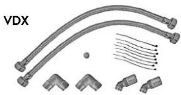
natural_image
Product diagram of VDX connectors with multiple tubes and connectors (no text or symbols)UDX
natural_image
Product assembly of flexible hose connectors and connectors (no text or symbols visible)natural_image
Technical line drawing of a mechanical bracket assembly (no text or symbols)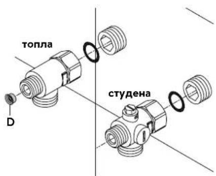
text_image
топла D студенаnatural_image
Technical line drawing of a mechanical assembly with no visible text or symbolsМонтиране на уреда
natural_image
Technical line drawing of a mechanical bracket assembly (no text or symbols)
text_image
co 30°
text_image
co 30°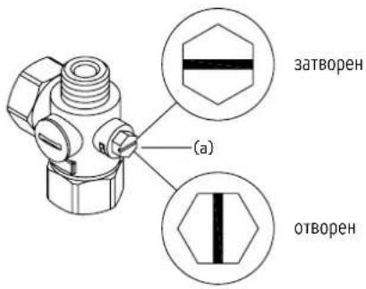
text_image
Technical diagram showing mechanical assembly with labeled components and directional arrowstext_image
180mm 60mm 8mm

text_image
Technical diagram of an electrical enclosure with labeled component 'S' and directional arrow indicating flow or movement.text_image
GEPRÜFT APPROVEDMultiple Power System MPS®:
text_image
Technical diagram showing a disassembled electronic device with labeled parts and a tool inserted into it.Повторно пускане в експлоатация
text_image
Technical diagram showing a mechanical component with an inset close-up of a textured surface, annotated with directional arrows and cross-sections.https://partner.clage.com/en/service/device-registration/

Uputstvo za upotrebu
Napomena: Priložene sigurnosne napomene pažljivo i potpuno pročitati pre instalacije, puštanja u rad i korišćenja kao i dalje postupanje, a poštovati i predviđenu namenu!
1. Opsi uređaja

natural_image
White industrial water heater with digital display showing 38% and control buttons (no text or symbols on main body)E-komfort protočni bojler DEX Next je elektronski kontrolisan protočni bojler sa grafičkim E-Paper displejem i senzorskim dugmadima za komforno i štedljivo napajanje vodom jedne ili više slavina.
Elektronika reguliše potrošnju energije u zavisnosti od odabrane izlazne temperature, postojeće ulazne temperature i količine protoka, kako bi u stepen precizno bila postignuta i konstantno održavana podešena temperatura čak i prikom oscilacija pritiska. Željena izlazna temepartura od 20 °C do 60 °C se unosi preko senzorskih dugmadi i očitava na E-Paper displeju.
DEX Next poseduje intuitivno kretanje kroz menije u kojima se mogu kreirati različiti korisnički profili i očitavati prikupljeni podaci.
Dovodna temperatura može da iznosi do 70 °C, tako da je moguć i režim rada za dogrevanje, npr. u solarnim sistemima.
Protočni bojler se može koristiti u kombinaciji sa eksternim relejem za rasterećenje za elektronski kontrolisane protočne bojlere (za detalje vidi uputstvo za montažu).
Čim otvorite ventil za toplu vodu na slavini, protočni bojler se automatski uključuje. Kada zatvorite slavinu uređaj se automatski isključuje. Rukovanje protočnim bojlerom se obavlja ili direktno na uređaju ili preko opcionalnog daljinskog upravljanja.
2. Ekologija i reciklaža
natural_image
Symbol of a trash bin crossed out by two diagonal lines (no text or numbers present)text_image
Statistics User Settings Info OK
text_image
Consumption last tapping Σ 0.52 € Duration 2m30s Water 65.4 l Ø Power 0.9 kWh | ← ↑ ↓Glavni meni
text_image
Enter PIN 08 00 ← ^ √ →
text_image
RepeatPIN 08 00 ← ^ ✓ OKtext_image
User 1 User 2 User 3 User 4 OK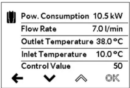
text_image
Pow. Consumption 10.5 kW Flow Rate 7.0 l/min Outlet Temperature 38.0 °C Inlet Temperature 10.0 °C Control Value 50 ← √ ↑ OKKorisnik »User«
Svaki od četiri korisnička profila može da poseduje sopstvenu profilnu sliku. Profilna slika se prikazuje na glavnom prikazu.
Na glavnom komandom ekranu svaki korisnik može da odredi i memoriše svoje sopstvene željene temperature za različite vrste primene.
natural_image
Simple black-and-white line drawing of a tree with two roots and a cloud at the top (no text or symbols)text_image
Warning symbol with exclamation mark inside trianglePopravke može da obavlja samo specijalizovani servis.
Ukoliko pomoću ove tabele ne možete da otklonite grešku uredaja, obratite se korisničkom servisu. Pripremite podatke sa tipske pločice uredaja!
Trimaran d.o.o.
Mihajla Pupina 17/3 smun
11185 Beograd
Srbija
Telefon: +381 11 4051 350
natural_image
3D mechanical assembly diagram showing internal components and mounting holes (no text or symbols)VDX
natural_image
Product diagram of a flexible hose assembly with multiple connectors and terminal parts (no text or symbols)UDX

natural_image
Product assembly of flexible hose connectors and connector parts (no text or symbols visible)Pribor za montažu
Za instalacije u teškim uslovima ugradnje postoji pribor za montažu:
Okvir za montažu RDX 3
(art.br. 36100)
Pomoću okvira za montažu moguće je montirati protočni bojler kada električni priključak izlazi iz zida na bilo kom mestu ispod uređaja.
natural_image
Technical line drawing of a mechanical bracket assembly (no text or symbols)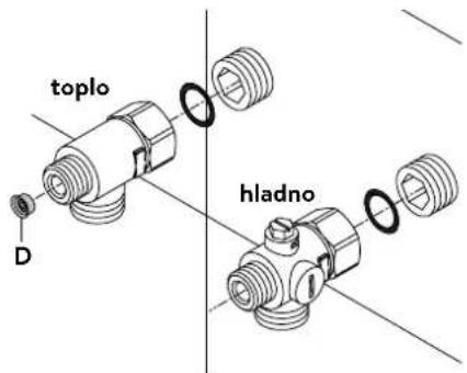
text_image
toplo hladno DInstalacija priključnih fitinga za vodu
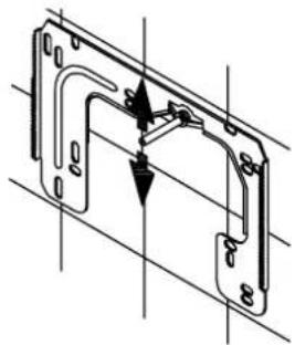
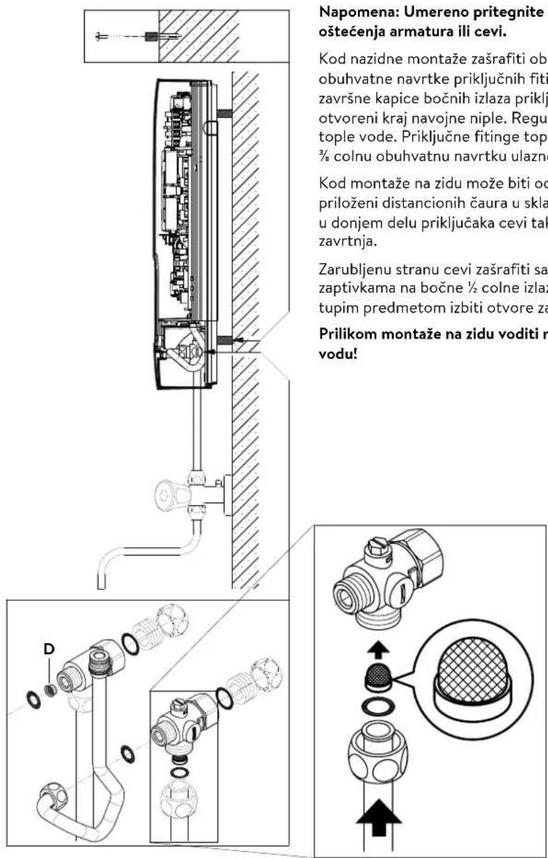
Napomena: Umereno pritegnite obuhvatne navrtke da obezbedite zaptivanje bez oštećenja armatura ili cevi.
- U skladu sa slikom zašrafite priključni fiting za hladnu vodu sa obuhvatnom navrtkom i zaptivkom od 12 cola na priključak za hladnu vodu.
- U skladu sa slikom zašrafite priključni fiting za toplu vodu sa obuhvatnom navrtkom i zaptivkom od ½ cola na priključak za toplu vodu.
- Uvucite regulator količine protoka »D« u priključni komad tople vode. O-prsten mora da bude vidljiv.
4. Instalacija

natural_image
Technical line drawing of a mechanical assembly with no visible text or symbolsSR
text_image
zatvoreno (a) otvorenoMontaža uređaja
- Moguće je da se kabl za dovod struje nalazi u gornjem delu uređaja ili na zidu. U tom slučaju prvo pratite korake jedan do tri iz opisa »Električni priključak odozgo« iz poglavlja »Električni priključak«.
- Postavite uređaj na zidni držač tako da navojna šipka zidnog držača ulazi u za to predviđeni otvor na uređaju. Pažljivim savijanjem navojne šipke zidnog držača po potrebi možete da izvršite manje korekture. Priključne cevi za vodu uređaja moraju da se ušrafe bez primene sile.
- Zašrafite plastične nareckane navrtke na navojnu šipku zidnog držača.
- Zašrafite obe % colne obuhvatne navrtke priključnih cevi za vodu uređaja sa % colnom zapivkom na instalirane priključne fitinge.
natural_image
Technical line drawing of a mechanical bracket assembly (no text or symbols)
text_image
φ30°
text_image
co 30°- Otvorite dovod vode i okrenite zaporni ventil (a) u priključnom fitingu hladne vode polako na (položaj »otvoreno«). Proverite sve spojeve na curenje.
- Zatim više puta otvorite i zatvorite odgovarajuću slavinu za toplu vodu sve dok iz cevi ne prestane da izlazi vazduh i dok protočni bojler ne bude odzračen.
5. Montaža na zidu
text_image
Napomena: Umereno pritegnite oštećenja armatura ili cevi. Kod nazidne montaže zašrafiti obu obuhvatne navrtke priključnih fiti završne kapice bočnih izlaza priklj otvoreni kraj navojne niple. Regul tople vode. Priključne fitinge topl 3/8 colnu obuhvatnu navrtku ulazne Kod montaže na zidu može biti od priloženi distancionih čaura u skla u donjem delu priključaka cevi tak zavrtnja. Zarubljenu stranu cevi zašrafiti sa zaptivkama na bočne ½ colne izlaz tupim predmetom izbiti otvore za Prilikom montaže na zidu voditi ra vodu!Napomena: Umereno pritegnite obuhvatne navrtke da obezbedite zaptivanje bez oštećenja armatura ili cevi.
Kod nazidne montaže zašrafiti obe ½ colne navojne niple i ½ colne zaptivke na ½ colne obuhvatne navrtke priključnih fitinga za toplu i hladnu vodu. Demontirati obe ½ colne završne kapice bočnih izlaza priključnih fitinga za toplu i hladnu vodu i zašrafiti ih na otvoreni kraj navojne niple. Regulator količine protoka »D« uvucite u priključni fiting tople vode. Priključne fitinge tople i hladne vode zašrafiti sa ¾ colnim zaptivkamana ¾ colnu obuhvatnu navrtku ulazne i izlazne cevi uređaja.
Kod montaže na zidu može biti od pomoći da se uređaj montira na rastojanju pomoću priloženi distancionih čaura u skladu sa crtežom pored. Oba otvora za pričvršćivanje u donjem delu priključaka cevi takođe propisno fiksirati pomoću tiplova od 6 mm i zavrtnja.
Zarubljenu stranu cevi zašrafiti sa ½ colnim obuhvatnim navrtkama i ½ colnim zaptivkama na bočne ½ colne izlaze priključnih fitinga za toplu i hladnu vodu. Zatim tupim predmetom izbiti otvore za cevi na haubi.
Prilikom montaže na zidu voditi računa: Postavite sito u priključni fiting za hladnu vodu!
text_image
Technical diagram showing mechanical assembly with labeled components and directional arrows, likely illustrating a fluid or cooling system.text_image
180mm 60mm 8mm

text_image
Technical diagram of an electronic device with labeled component 'S' and directional arrow indicating flow or movement.Električni priključak odozgo
Uverite se da je napajanje strujom isključeno pre povezivanja uređaja na električnu mrežu!
- Otvorite postojeće mesto za probijanje otvora na gornjem delu uređaja (S) po perforaciji snažnim pritiskom tupim alatom (npr. odvijačem). Kada je električni priključni kabl postavljen na zidu, dodatno otvorite otvor na desnoj strani donjeg dela uređaja.
- Isecite rukavac iz kesice sa priborom u skladu sa poprečnim presekom dovodnog kabla. Pri tom dimenzionirajte otvor rukavca nešto manje od poprečnog preseka priključnog kabla da bi ste postigli optimalnu zaštitu od vode. Prilagodite rukavac u skladu sa otvorom. Obavezno koristiti zaštitni rukvac!
- Skinite omotač priključnog kavla tako da rukavac ulazi u unutrašnjost uređaja. Uzimte pripremljeni uređaj u jednu ruku a drugom rukom provucite kabl kroz rukavac.
- Postavite uređaj na zidni držač, provucite navojnu šipku zidnog držača kroz za to predviđeni otvor na uređaju i fiksirajte uređaj.
- Preklopite preklopni držač u desnu stranu.
- Oslobodite zavrtanj za pričvršćivanje priključne kleme. Premestite priključnu klemu na gornju stopu i ponovo je pričvrstite.
- Ogolite pojedinačne žice priključnog kabla i povežite ih na priključne kleme u skladu sa elektro šemom. Povežite uredaj na zaštitni provodnik.
- Preklopite unazad preklopni držač i uklopite ga.
- Postavite haubu na uređaj i ušrafite zavrtanj za pričvršćivanje. Zatim možete da navučete masku odozdo do graničnika.
Note: To ensure IP25 protection class, please don't remove the bottom water splash protection sleeve.
text_image
GEPRÜFT APPROVEDMultiple Power System MPS®:
Nazivna snaga (maks. primljena snaga) iznosi 27 kW pri 400 V i može se interno promeniti na 24 kW, 21 kW ili 18 kW!
text_image
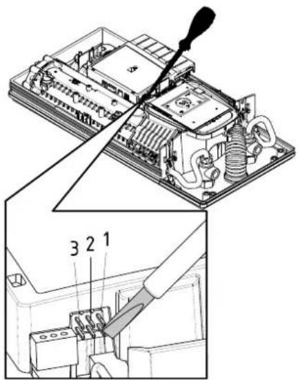
Technical diagram showing a disassembled electronic device with labeled parts and a tool inserted into it.Pre električnog povezivanja napunite vodom vodovodnu mrežu i uređaj kroz laganih otvaranja i zatvaranja slavine za toplu vodu i time je potpuno odzračite.
U tom cilju izvadite event. postavljene regulatore mlaza (perlatore) iz armature da bi ste obezbedili maksimalan protok. Isperite instalaciju tople i hladne vode u trajanju od najmanje jednog minuta.
Uređaj je potrebno ponovo odzračiti posle svakog pražnjenja (npr. posle radova na vodovodnoj instalaciji, zbog opasnosti od smrzavanja ili posle popravke uredaja) i pre ponovnog puštanja u rad.
Ukoliko se protočni bojler ne može pustiti u rad, proverite da li su se usled transporta aktivirali sigurnosni limitator temperature (STB) ili sigurnosni presostat (SDB). Uverite se da li je uređaj pod naponom i po potrebi resetujte sigurnosti prekidač.
Promena snage
Ovo može da obavlja samo ovlašćeno stručno lice, u suprotnom dolazi do gašenja garancije!
text_image
Technical diagram showing internal components of an air conditioner unit with numbered parts and a schematic illustrating the assembly process.Poz. ISKLJ Poz. 1
Funkcija zaključavanja
Moguće je ograničiti obim rukovanja uređajem.
Aktiviranje funkcije zaključavanja
- Podesite željeni parametar u meniju podešavanja (vidi online u uputstvu za upotrebu poglavlje »Podešavanja«, odeljak »Ograničenje temperature« i/ili »Rasterećenje«).
- Odvojte uređaj od strujne mreže (npr. isključivanjem osigurača).
- Svucite džamper sa naponske elektronike i postavite ga na poziciju »1« (vidi sliku).
- Ponovo pustite uredaj u rad.
Deaktiviranje funkcije zaključavanja
- Odvojte uređaj od strujne mreže (isključite osigurače).
- Svucite džamper sa naponske elektronike i postavite ga na poziciju »ISKLJ« (vidi sliku).
- Ponovo pustite uređaj u rad.
8. Radovi na održavanju
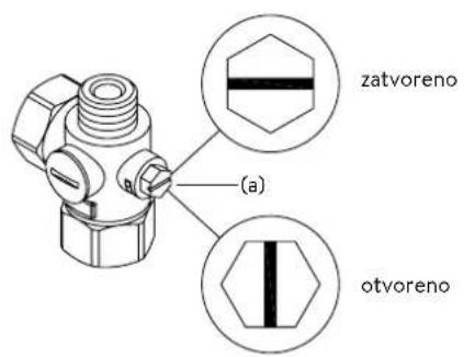
text_image
zatvoreno (a) otvoreno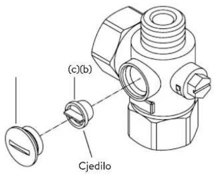
text_image
(c)(b) CjediloRadove na održavanju može da obavlja samo ovlašćeni specijalizovani servis.