DCX Next - Boiler Clage - Free user manual and instructions
Find the device manual for free DCX Next Clage in PDF.
| Brand | Clage |
| Model | DCX Next |
| Product type | Electronic instantaneous water heater |
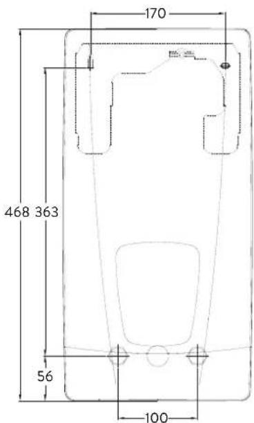
| Dimensions (H x W x D) | 468 x 170 x 363 mm |
| Weight (with water) | 4.2 kg |
| Electrical supply | Three-phase 380–415 V AC, 50/60 Hz |
| Adjustable nominal power | 18, 21, 24 or 27 kW depending on setting |
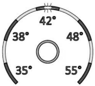
| Preset temperatures | 35 °C, 38 °C, 42 °C, 48 °C, 55 °C |
| Start-up flow rate | 1.5 l/min |
| Maximum flow rate | 8.0 l/min |
| Nominal pressure | 1.0 MPa (10 bar) |
| Water connection | G 1/2" |
| Heating system | Bare wire IES® |
| Protection class | IP25 |
| Energy efficiency class | A (EU 812/2013) |
| Annual electricity consumption | 471 kWh (load profile M) |
| Sound power level | 15 dB(A) |
| Display and control | 5 color LEDs, central touch button |
| Safety | Temperature limiter (STB), pressure limiter (SDB), IP25 protection |
| Maintenance | Filter cleaning, purging after draining, inspection every 3 years |
| Included accessories | Wall bracket, mounting template, gasket, etc. |
Frequently Asked Questions - DCX Next Clage
User questions about DCX Next Clage
0 question about this device. Answer the ones you know or ask your own.
Ask a new question about this device
Download the instructions for your Boiler in PDF format for free! Find your manual DCX Next - Clage and take your electronic device back in hand. On this page are published all the documents necessary for the use of your device. DCX Next by Clage.
USER MANUAL DCX Next Clage
DCX Next / DCX 13 Next
E-convenience instant water heater
DCX Next / DCX 13 Next

de > 2
en > 18
fr > 34
nl > 51
pt > 68
es > 85
pl > 102
ru > 119
cs > 136
sk > 153
bg > 170
sr > 187

text_image
COMPOET 42° 38° 48° 35° 55° ECO HOT CLAGE PHOTO (2019/01)Inhaltsverzeichnis
Gebrauchsanleitung
text_image
Warning symbol with exclamation mark inside trianglenatural_image
3D mechanical assembly diagram showing internal components and mounting holes (no text or symbols)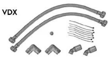
natural_image
Technical illustration of VDX connectors and terminal blocks (no text or symbols)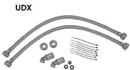
natural_image
Product assembly of UDX connectors and wiring (no text or symbols visible)Zu beachten sind:
text_image
warm kalt Dnatural_image
Technical line drawing of a mechanical bracket assembly (no text or symbols)natural_image
Technical line drawing of an internal electronic device with ports, connectors, and wiring (no text or symbols)Gerät montieren
natural_image
Technical line drawing of a mechanical bracket assembly with mounting holes and internal components (no text or symbols)
text_image
co30°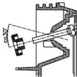
text_image
co 30°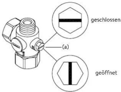
text_image
Technical diagram of an electronic device with labeled components and internal wiring, showing exploded and assembled views.Lastabwurfrelais
text_image
180mm 60mm 8mm

text_image
Technical diagram of an electrical or mechanical device with labeled component 'S' and internal structure showing connections and components.Multiple Power System MPS®:
text_image
DCX Next DCX13 Nexttext_image
Technical diagram of an air conditioner unit with labeled components and internal wiring
flowchart
graph TD
    A["3"] --> B["2"]
    B --> C["1"]
    D["3"] --> E["2"]
    E --> F["1"]
    G["3"] --> H["2"]
    H --> I["1"]
Pos. AUS Pos. 3
Bedienfeldsperre
text_image
Technical diagram showing a mechanical component with an inset close-up of a textured surface, illustrating assembly or assembly process.Operation instruction
- Description of the appliance .... 19
- Environment and recycling ..... 19
- How to use 20
Temperature setting 20
Power limit 20
Device information 20
Venting after maintenance work....21
Cleaning and maintenance....21
- Trouble-shooting and service....22
- Product data sheet in accordance with EU regulation - 812/2013 814/2013 22
Installation instruction
- Overview....23
- Technical specifications .....24
- Dimensions....24
- Installation....25
Installation site....25
Mounting accessories 25
Installing the wall bracket....26
Installing connection pieces....26
Installing the appliance 27
- Direct connection 28
- Electrical connection 29
Wiring diagram....29
Structural prerequisites 29
Load shedding relay....29
Electrical connection from below....30
Electrical connection from above....30
- Initial operation 31
Selection of power rating....31
Control panel lock....32
- Maintenance work....33
Cleaning and replacing the filter strainer 33
Cleaning and replacing the filter strainer if direct connected....33
The documents supplied with the device must be stored carefully.
Registration
Register your device online on our website and benefit from our services under warranty.
Your full details help our customer service process your request as fast as possible.
For online registration, just follow the link below or use the QR code with your smartphone or tablet.
https://partner.clage.com/en/service/device-registration/

Operation instruction
Note: Carefully read the enclosed safety instructions through in full before the appliance is installed, put into service and used and follow them in the further steps and during use!
1. Description of the appliance

natural_image
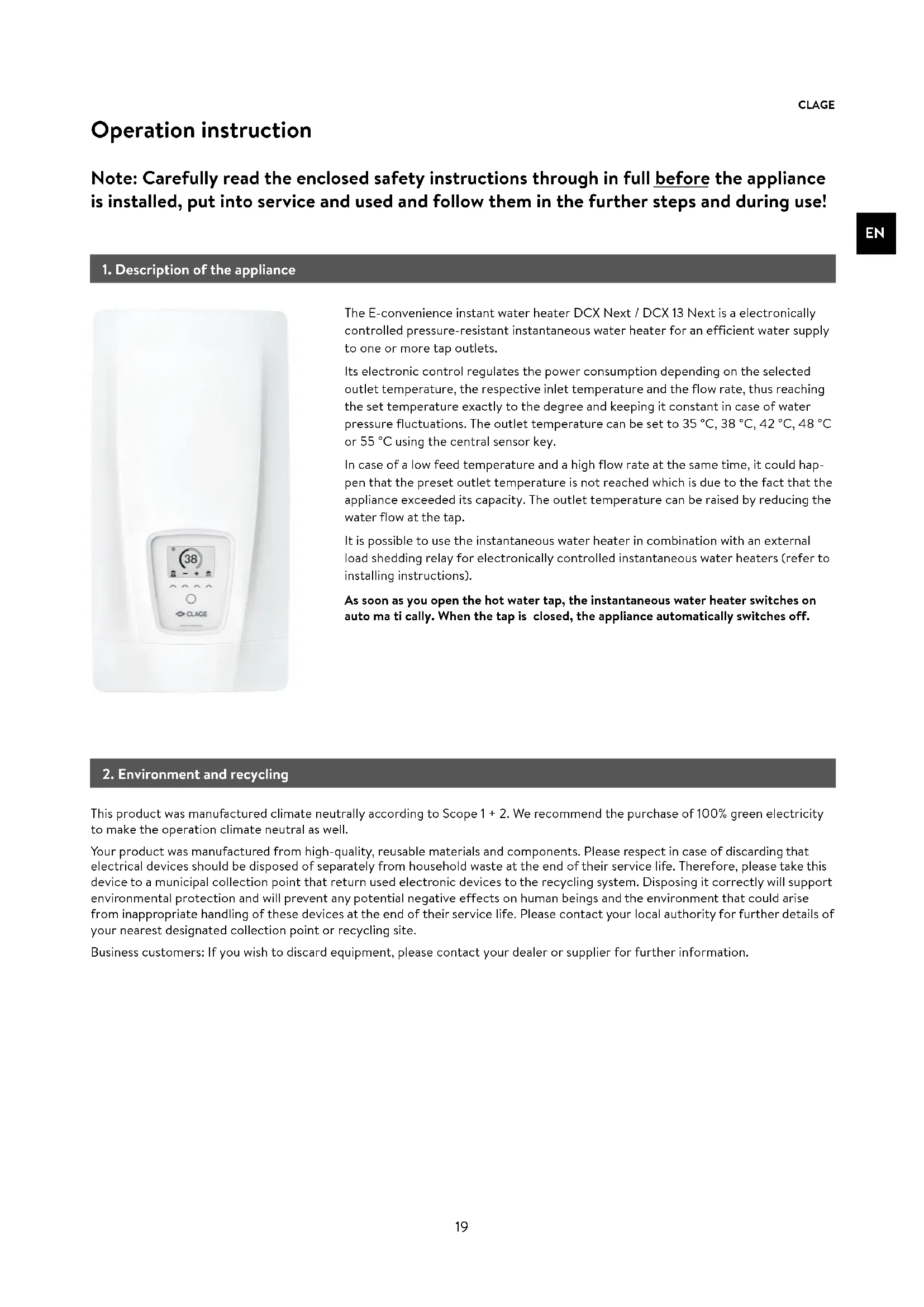
Close-up of a white industrial water heater with a digital display showing 38-degree angle and control buttons (no readable text or symbols beyond basic design)The E-convenience instant water heater DCX Next / DCX 13 Next is a electronically controlled pressure-resistant instantaneous water heater for an efficient water supply to one or more tap outlets.
Its electronic control regulates the power consumption depending on the selected outlet temperature, the respective inlet temperature and the flow rate, thus reaching the set temperature exactly to the degree and keeping it constant in case of water pressure fluctuations. The outlet temperature can be set to 35 °C, 38 °C, 42 °C, 48 °C or 55 °C using the central sensor key.
In case of a low feed temperature and a high flow rate at the same time, it could happen that the preset outlet temperature is not reached which is due to the fact that the appliance exceeded its capacity. The outlet temperature can be raised by reducing the water flow at the tap.
It is possible to use the instantaneous water heater in combination with an external load shedding relay for electronically controlled instantaneous water heaters (refer to installing instructions).
As soon as you open the hot water tap, the instantaneous water heater switches on auto ma ti cally. When the tap is closed, the appliance automatically switches off.
2. Environment and recycling
This product was manufactured climate neutrally according to Scope 1 + 2 . We recommend the purchase of 100% green electricity to make the operation climate neutral as well.
Your product was manufactured from high-quality, reusable materials and components. Please respect in case of discarding that electrical devices should be disposed of separately from household waste at the end of their service life. Therefore, please take this device to a municipal collection point that return used electronic devices to the recycling system. Disposing it correctly will support environmental protection and will prevent any potential negative effects on human beings and the environment that could arise from inappropriate handling of these devices at the end of their service life. Please contact your local authority for further details of your nearest designated collection point or recycling site.
Business customers: If you wish to discard equipment, please contact your dealer or supplier for further information.
3. How to use

gauge
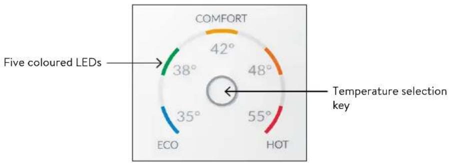
| Color | Value | | --------- | ----- | | Green | 38° | | Orange | 42° | | Orange | 48° | | Red | 55° | | Blue | 35° |Temperature setting
The temperature selection key ○ allows you to quickly select one of five preset temperatures, that are typical for hot water applications: "Hand wash" 35 °C, "Shower" 38 °C, "Bath tub" 42 °C, "Kitchen" 48 °C and "Cleaning" 55 °C.
Every key press sets the temperature to the next level:
$$ 3 5 ^ {\circ} \mathrm{C} \bigcirc 3 8 ^ {\circ} \mathrm{C} \bigcirc 4 2 ^ {\circ} \mathrm{C} \bigcirc 4 8 ^ {\circ} \mathrm{C} \bigcirc 5 5 ^ {\circ} \mathrm{C} $$
Pressing the key ○ once again, starts the cycle all over.
The currently selected temperature is indicated by one of five coloured LEDs.
radar
| Angle (°) | |-----------| | 42 | | 38 | | 48 | | 35 | | 55 |Power limit
If the full output of the instantaneous water heater DCX Next does not suffice to heat the tapped quantity of water, this will be indicated by flashing of the temperature LED (e.g. in winter time, when opening several taps at once). When you reduce the hot water flow rate, the LED lights up continuously again because the output of the appliance is again sufficient to reach the set temperature.
Device information
Press and hold the temperature selection key for 10 seconds to open the info mode. After ten seconds, all LEDs light up once briefly and then switch off again immediately to confirm that the info mode is active. The device status is displayed via the LEDs:
LED bottom left: OFF = no water flow; FLASHING = water flow below switch-on point; ON = water flow above switch-on point.
LED top middle: ON = heating active; FLASHING = power limit. Otherwise OFF.
LED bottom right: OFF = device OK; FLASHING = error detected (inform customer service)
The display returns to normal operation after 60 seconds or after a key press.
3. How to use

Venting after maintenance work
This instantaneous water heater features an automatic air bubble protection to prevent it from inadvertently running dry. Nevertheless, the appliance must be vented before using it for the first time. Each time the appliance is emptied (e.g. after work on the plumbing system, if there is a risk of frost or following repair work), the appliance must be re-vented before it is used again.
- Disconnect the instantaneous water heater from the mains (e.g. via deactivating the fuses).
- Unscrew the jet regulator on the outlet fitting and open the cold water tap valve to rinse out the water pipe and avoid contaminating the appliance or the jet regulator.
- Open and close the hot water tap until no more air emerges from the pipe and all air has been eliminated from the water heater.
- Only then should you re-connect the power supply again (e.g. via activating the fuses) to the instantaneous water heater and screw the jet regulator back in.
- The appliance activates the heater after approx. 10 seconds of continuous water flow.
Cleaning and maintenance
- Plastic surfaces and fittings should only be wiped with a damp cloth. Do not use abrasive or chlorine-based cleaning agents or solvents.
- For a good water supply, the outlet fittings (e.g. jet regulators and shower heads) should be unscrewed and cleaned at regular intervals. Every three years, the electrical and plumbing components should be inspected by an authorised professional in order to ensure proper functioning and operational safety at all times.
4. Trouble-shooting and service
EN

text_image
Warning symbol with exclamation mark inside triangleRepairs must only be carried out by authorised professionals.
If a fault in your appliance cannot be rectified with the aid of this table, please contact the service organisation of your importer or the Central Customer Service Department. Please have the details of the typeplate at hand.
CLAGE GmbH
After-Sales Service
Pirolweg 4
21337 Lüneburg
Germany
Phone: +49 4131 8901-400
Email: service@clage.de
This instantaneous water heater was manufactured conscientiously and checked several times before delivery. Should malfunctions nevertheless occur, it is usually only due to a bagatelle. First attempt to switch the house fuses off and on again in order to reset the electronics. Next, try to remedy the problem with reference to the following table. In doing so, you will avoid unnecessary expense of customer service assistance.
| DCX Next / DCX 13 Next | ||
| Problem | Cause | Solution |
| Water stays cold, temperature LED does not light up | Master fuse tripped | Renew or activate fuse |
| Safety pressure cut-out tripped | Contact customer service | |
| Water stays cold, temperature LED does light up | Safety thermal cut-out tripped | Contact customer service |
| Water stays cold, all LEDs flash | Internal error | Contact customer service |
| Water heats up, all LEDs flash with exception of the temperature indication | Appliance detected an error | Contact customer service |
| Flow rate of hot water too weak | Outlet fitting dirty or calcified | Clean shower head, jet regulator or sieves |
| Fine filter dirty or calcified | Let clean fine filter by customer service | |
| Temperature indication LED flashes | Power limit reached | Decrease the warm water flow at the tap |
| Selected temperature is not reached | Cold water has been added via the tap | Tap hot water only; set temperature, check outlet temperature |
| Sensor key does not respond correctly or only sporadically | Display is wet | Dry display by wiping it with a soft cloth |
5. Product data sheet in accordance with EU regulation - 812/2013 814/2013
| a b c d e f h i | ||||||||
| b.1 b.2 | _WH % kWh | AEC °C LdB(A) | WA | |||||
| CLAGE | DCX Next | 5E-270P-3B | S | A | 39 | 471 | 55 | 15 |
| CLAGE | DCX13 Next | 5E-135P-3B | S | A | 39 | 472 | 55 | 15 |
Explanations
a Brand name or trademark
b.1 Model
b.2 Type
c Specified load profile
d Energy-efficiency class
e Energy-efficiency
f Annual power consumption
g Additional load profile, the appropriate energy-efficiency and the annual power consumption, if applicable
h Temperature setting for the temperature controller
i Sound power level, internal
Additional notes


All specific precautions for assembly, installation, maintenance and use are described in the operating and installation instructions.
All data in this product data sheet are determined by applying the specifications of the relevant European directives. Differences to other product information listed elsewhere may result in different test conditions.
The power consumption was determined in compliance with standardized measurement method based on EU guidelines. The real energy consumption is pending on individual requirements.
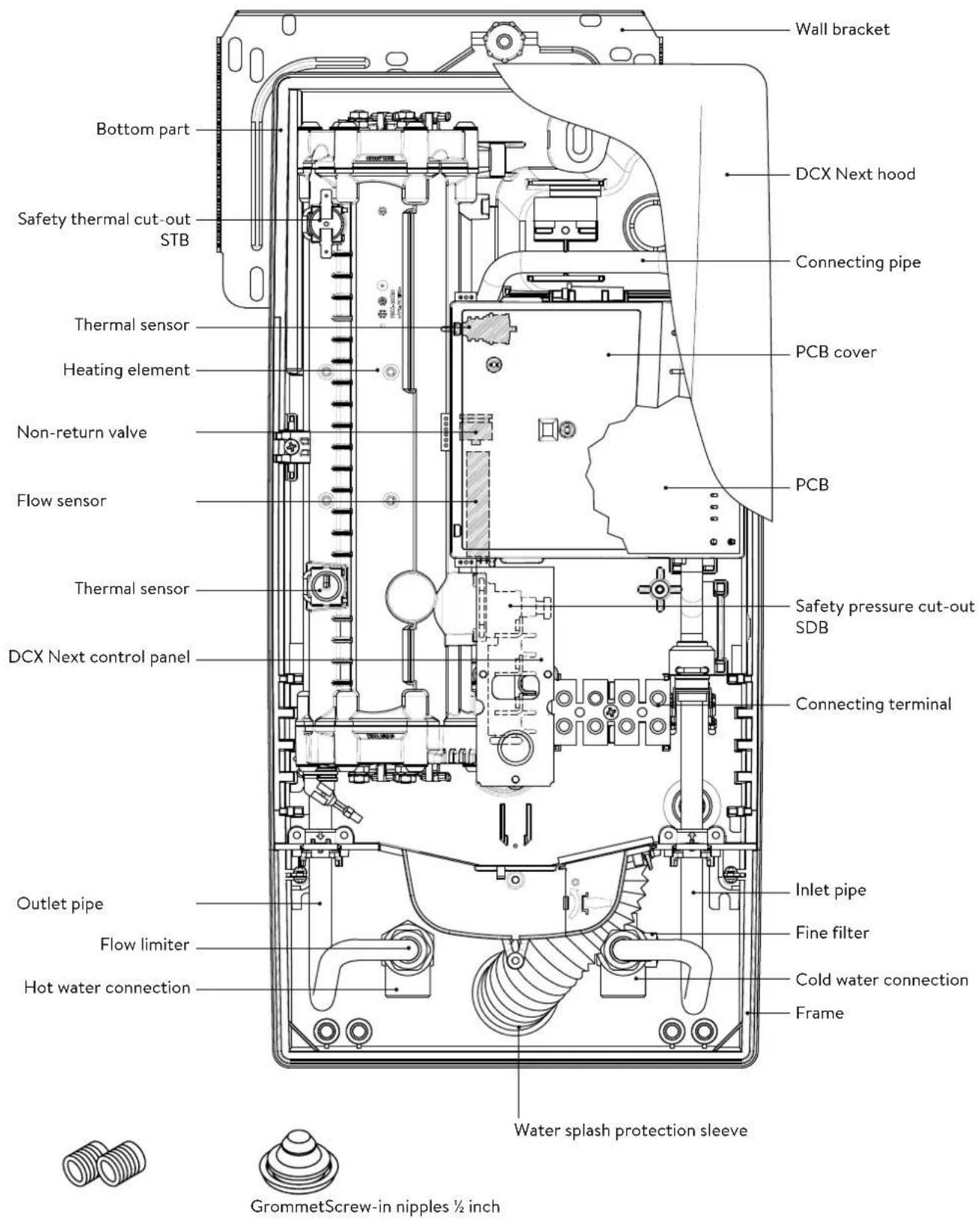
1. Overview
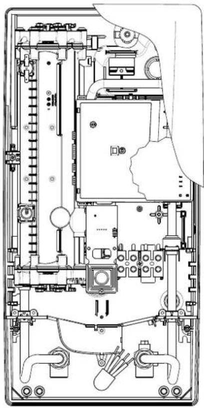
text_image
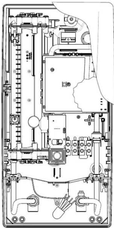
Wall bracket DCX Next hood Connecting pipe PCB cover Non-return valve PCB Flow sensor Thermal sensor Safety pressure cut-out SDB DCX Next control panel Connecting terminal Outlet pipe Inlet pipe Flow limiter Fine filter Cold water connection Hot water connection Frame Water splash protection sleeve GrommetScrew-in nipples ½ inch2. Technical specifications
| Model DCX13 Next DCX Next | ||||||
| Energy efficiency class A * | ) | |||||
| Rated capacity / rated current | 11kW..13.5kW (16A..20A) | 18kW..27kW (26A..39A) | ||||
| Chosen capacity / current 11kW /16A | 13.5kW /20A | 18kW /26A | 21kW /30A | 24kW /35A | 27kW /39A | |
| Electrical connection | 3~/PE 380..415V AC | 3~/PE 380..415V AC | 3~/PE 400V AC | |||
| Min.required cable size1) | 1.5mm2 | 2.5mm2 | 4.0mm2 | 4.0mm2 | 6.0mm2 | 6.0mm2 |
| Hot water (l/min)max.at Δt = 28 Kmax.at Δt = 38 K | 5.62)4.1 | 6.92)5.12) | 9.22)6.8 | 10.72)7.9 | 12.32)9.02) | 13.82)10.22) |
| Rated volume 0.4 l | ||||||
| Rated pressure | 1.0 MPa (10 bar) | |||||
| Connecting type | pressure-resistant / pressureless | |||||
| Heating system | Bare wire heating system IES® | |||||
| @ 15°C:Required specific water resistanceSpecific electrical conductivity | ≥ 1100Ωcm≤ 90mS/m | |||||
| Inlet temperature | ≤ 30°C | |||||
| Flow rate to switch on - max. flow rate | 1.5 l/min - 5.03) | 1.5 l/min - 8.03) | ||||
| Pressure loss | 0.08 bar at 1.5 l/min 1.3 bar at 9.0 l/min3) | |||||
| Temperature range | 35°C / 38°C / 42°C / 48°C / 55°C | |||||
| Water connection | G1⁄2 inch | |||||
| Weight (when filled with water) | 4.2 kg | |||||
| VDE class of protection | I | |||||
| Type of protection / safety | (D324) [DWXX] IP25 CE | |||||
*) The declaration complies with the EU regulation No 812/2013.
1) Maximum applicable cable size is 10 mm² at electrical connection from above
2) Mixed water
3) Flow rate limited to achieve optimum temperature rise
4) Without flow regulator
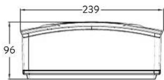
3. Dimensions
text_image
170 468 363 56 100Dimensions in mm
text_image
239 964. Installation
text_image
CLAGE Lüneburg DIN 4109 PA-IX 16951/I MPA NRW.Based on the national constitution guidelines a general test certificate concerning the evidence of applicability of noise behaviour is granted.
The following regulations must be observed:
• e.g. VDE 0100
• EN 806
- Installation must comply with all statutory regulations, as well as those of the local electricity and water supply companies.
• The rating plate and technical specifications
- Only intact and appropriate tools must be used
Installation site
- Appliance must only be installed in frost-free rooms. Never expose appliance to frost.
- The Appliance must be wall mounted and has to be installed with water connectors downward or alternative transversely with water connections left.
- The appliance complies with protection type IP25 and may therefore be installed in protection zone 1 according to VDE 0100 part 701 (IEC 60364-7).
- In order to avoid thermal losses, the distance between the instantaneous water heater and the tap connection should be as small as possible.
• The appliance must be accessible for maintenance work. - Plastic pipes may only be used if they conform to DIN 16893, Series 2.
- The specific resistance of the water must be at least 1100 Ω cm at 15 °C. The specific resistance can be asked for with your water distribution company.
natural_image
3D mechanical assembly diagram showing internal components and mounting holes (no text or symbols)
natural_image
Technical illustration of VDX pipe fittings and connectors (no text or symbols)
natural_image
Product diagram of UDX cable connectors and connector components (no text or symbols)Mounting accessories
For installations under difficult conditions, these mounting accessories are available:
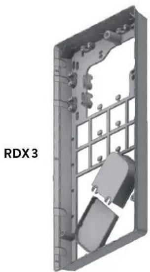
Mounting frame kit RDX3
(Art. no. 36100)
The instant water heater can be installed by means of this mounting kit in the below situations. The power supply cable is coming out of the wall at any place from behind the unit, but the wall has unusual surface conditions, making it difficult for installing the water heater.
When using the RDX the protection class changes from IP25 to IP24.
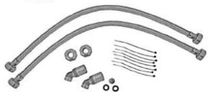
Extension kit VDX
(Art. no. 34120) - RDX / RDX 3 is necessary! -
The instant water heater can be installed by means of this extension kit if the water pipes are coming displaced or exchanged out of the wall or if they are coming edge-wise on the wall to the unit. The power supply could come out of the wall at any place under the unit or the wiring could be installed surface-mounted.
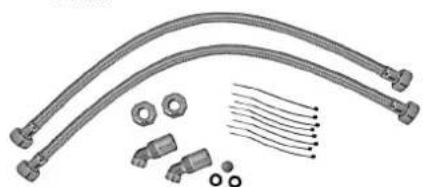
Extension kit UDX
(Art. no. 34110) - RDX / RDX 3 is necessary! -
The instant water heater can be installed by means of this extension kit if the water-connections are expiring above the unit. The power supply could come out of the wall at any place under the unit or the wiring could be installed surface-mounted.
4. Installation

text_image
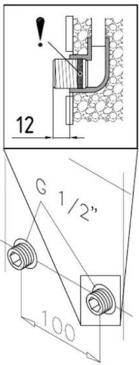
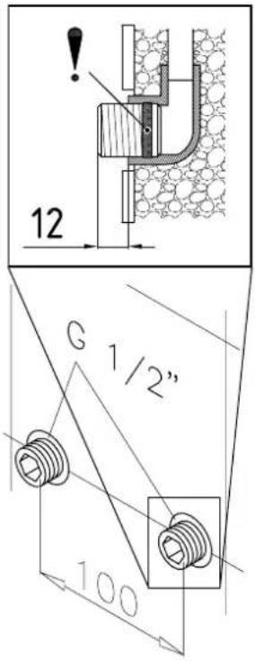
12 G 1/2" 100

text_image
warm cold DInstalling the wall bracket
Note: If you install this instantaneous water heater in exchange for a conventional instantaneous water heater, there is generally no need to drill holes for the wall bracket, in this case step 2 would not be necessary.
Thoroughly rinse the water supply pipes before installation to remove soiling from the pipes.
- Using a 12 mm hexagon socket screw key, screw the screw-in nipples into the wall connections. The seals must be fully screwed into the thread. After tightening, the double nipples must protrude by 12 - 14 mm.
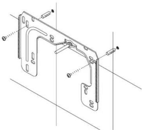
- Hold the included mounting template on the wall and align it so that the holes in the template fit over the double nipples. Mark the drill holes according to the template and drill them using a 6 mm drill. Insert the included dowels.
- To open the appliance pull down the faceplate and unscrew the main hood screw. Lift the hood carefully, remove the plug from the control panel and note the position of the plug.
- Loosen the knurled nut of the wall bracket, remove the wall bracket and screw it on the wall. Offset tiling or uneven surfaces can be compensated by up to 30 mm with the aid of the spacers supplied. The spacers are fitted between the wall and the wall bracket.
natural_image
Technical line drawing of a mechanical bracket assembly (no text or symbols)Installing connection pieces
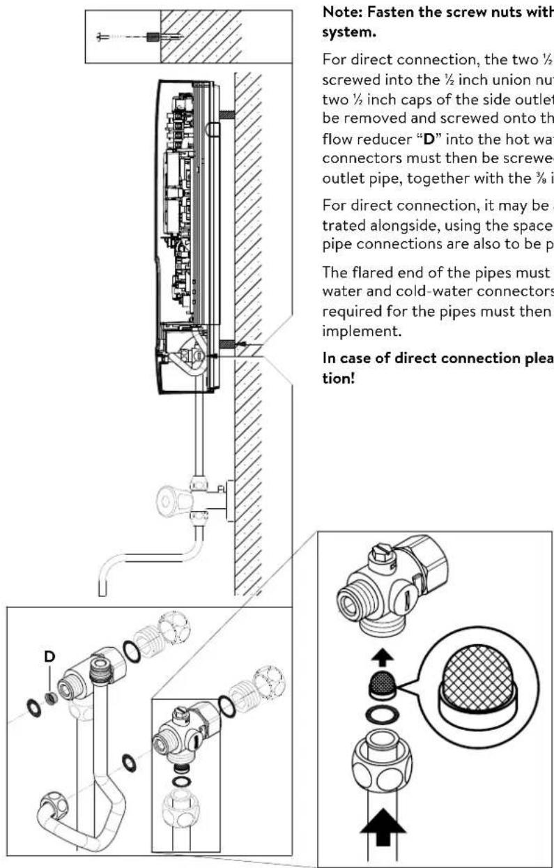
Note: Fasten the screw nuts with caution, to avoid damage to the valves or the piping system.
- As shown in the illustration, screw the cold water connection piece with the union nut and the 12 inch seal onto the cold water connection.
- Screw the hot water connection piece with the union nut and the 12 inch seal onto the hot water connection.
- Put the water flow limiter "D" into the hot water connection piece. The O-ring must be visible
4. Installation
natural_image
Technical line drawing of an electronic device interior with no visible text or symbols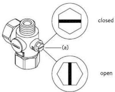
text_image
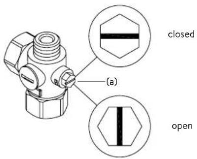
(a) closed openInstalling the appliance
- The electrical power supply cable may be connected in the upper part or is surface mounted. Only in such case, first follow the steps one through three according to the description "Electrical connection from above" in chapter "Electrical connection".
- Place the appliance on the heater bracket so that the threaded rod of the wall bracket fits in the corresponding hole of the appliance. If necessary, slight corrections are possible by carefully bending the threaded rod of the wall bracket. However, it must be possible to screw on the water connection pipes of the appliance without applying force.
- Screw the plastic knurled nut onto the threaded rod of the wall bracket.
- Screw the two 18 inch union nuts of the appliance's water connection pipes, each with the 38 inch seal, onto the fittings.

natural_image
Technical line drawing of a mechanical bracket assembly (no text or symbols)
text_image
co 30°
text_image
φ30°- Open the water supply line to the unit and slowly open (position "open") the shut-off valve (a) in the cold water connection piece. Check all connections for leaks.
- Next, open and close the hot water tapping valve several times until no more air emerges from the line and all air has been eliminated from the instantaneous water heater.
5. Direct connection

text_image
Note: Fasten the screw nuts with system. For direct connection, the two ½ screwed into the ½ inch union nut two ½ inch caps of the side outlet be removed and screwed onto the flow reducer "D" into the hot wat connectors must then be screwed outlet pipe, together with the ¾ in For direct connection, it may be a trated alongside, using the spacer pipe connections are also to be pi The flared end of the pipes must water and cold-water connectors required for the pipes must then implement. In case of direct connection plea- tion!Note: Fasten the screw nuts with caution, to avoid damage to the valves or the piping system.
For direct connection, the two 12 inch screw-in nipples and the 12 inch seals must be screwed into the 12 inch union nuts of the hot-water and cold-water connectors. The two 12 inch caps of the side outlets of the hot-water and cold-water connectors must be removed and screwed onto the open end of the screw-in nipples. Put the water flow reducer “D” into the hot water connection piece. The hot-water and cold-water connectors must then be screwed into the 38 inch union nut of the appliance inlet and outlet pipe, together with the 38 inch seals.
For direct connection, it may be advisable to mount the appliance at a distance as illustrated alongside, using the spacer sleeves supplied. The two fixing holes near the lower pipe connections are also to be professionally fixed with 6 mm dowels and screws.
The flared end of the pipes must be screwed into the 12 inch side outlets of the hot-water and cold-water connectors with 12 inch union nuts and 12 inch seals. The holes required for the pipes must then be opened of the housing with the aid of a blunt implement.
In case of direct connection please note: Put the strainer into the cold water connection!
6. Electrical connection
Wiring diagram
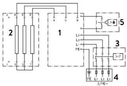
text_image
2 1 3/PE~ 4 L1 L2 L3 L1 PE 5 3 P 4 A B C B 1 2 3 4- Electronic circuitry
- Heating element
- Safety pressure cut-out
- Connecting terminal
- Safety thermal cut-out
Only by a specialist!
Please observe:
• e.g. VDE 0100
- The installation must comply with current IEC and national local regulations or any particular regulations, specified by the local electricity supply company
• The rating plate and technical specifications
• The appliance must be earthed!
Structural prerequisites
- The appliance must be installed via a permanent connection. Heater must be earthed!
- The electric wiring should not be injured. After mounting, the wiring must not be direct accessible.
- An all-pole disconnecting device (e.g. via fuses) with a contact opening width of at least 3 mm per pole should be provided at the installation end.
- To protect the appliance, a fuse element must be fitted with a tripping current commensurate with the nominal current of the appliance.
text_image
Technical diagram of an electronic device with labeled components and internal wiring, showing exploded and assembled views.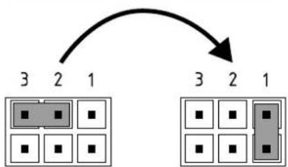
flowchart
graph TD
    A["3 2 1"] --> B["Grid with black squares"]
    C["3 2 1"] --> D["Grid with black squares"]
    style A fill:#ccc,stroke:#000
    style B fill:#ccc,stroke:#000
    style C fill:#ccc,stroke:#000
    style D fill:#ccc,stroke:#000
Pos. OFF Pos. 1
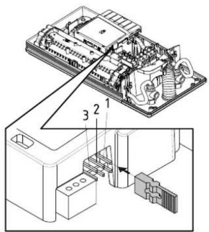
Load shedding relay
If further three-phase appliances are connected, a load shedding relay designed for electronic instantaneous water heaters (CLAGE no. 82250) can be connected to phase conductor L2.
To avoid possible jitter of the load shedding relay caused by low power consumption (low temperature set point and low water flow rate) the "Load-shedding-mode" can be activated as followed:
- Disconnect the appliance from the power supply (e.g. by switching of the fuses)
• Take the jumper off the power electronics and change to position "1" (see picture). - Put the appliance into operation again
6. Electrical connection


text_image
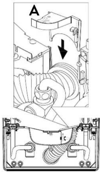
A CElectrical connection from below
Note: If necessary, the connecting terminal can be displaced to the upper part of the appliance. If you want to do so, please follow the instructions in the next chapter.
Check that the power supply is switched off prior to electrical connection!
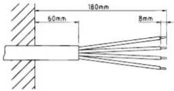
- Dismantle approximately 6 cm off the connecting cable above the wall outlet. With the smaller opening ahead, slide the water splash protection sleeve over the connecting cable so that the sleeve is flush with the wall. This prevents any leaking water from coming into contact with the electrical leads. It must not become damaged! The protection sleeve must be used!
- Strip the individual wires and plug them in the connecting terminals according to the wiring diagram. The appliance must be earthed.
- Pull the protective sleeve so far over the connecting cables and shape the connecting cables in such a way that the sleeve fits perfectly in the recess of the intermediate panel without mechanical tension and fix it with the sleeve fixing (A).
text_image
180mm 60mm 8mm

text_image
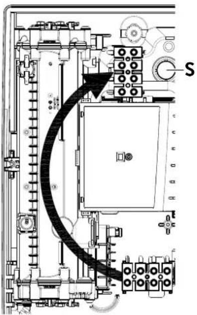
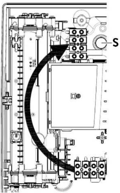
Technical diagram of an electrical or mechanical device with labeled component 'S' and directional arrow indicating flow or movement.Electrical connection from above
Check that the power supply is switched off prior to electrical connection!
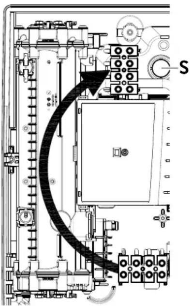
- Open the prepared breaking point (S) in the upper part of the appliance by pressing with a blunt implement (e.g. srewdriver). For surface-mounted connection cable additional open the breakout at the right side of the bottom part.
- Slit the grommet of the accessory set to match the cable size. The opening in the grommet should be slightly smaller than the cross-section of the cable in order to ensure optimum protection against water. Fit the grommet into the opening. The protection grommet must be used!
- Strip the connection cable so that the sheath extends through the grommet into the appliance. Hold the prepared appliance so that you can route the cable into the grommet with the other hand.
- Place the appliance on the wall bracket so that the threaded rod of the wall bracket fits in the corresponding hole of the appliance and fix it with the knurled nut.
- Unscrew the fastening screw of the connecting terminal. Displace the connecting terminal to the upper foot. Affix the connecting terminal again.
- Strip the individual wires of the connecting cable and plug them in the connecting terminals according to the wiring diagram. The appliance must be earthed.
Note: To ensure IP25 protection class, please don't remove the bottom water splash protection sleeve.
7. Initial operation
text_image
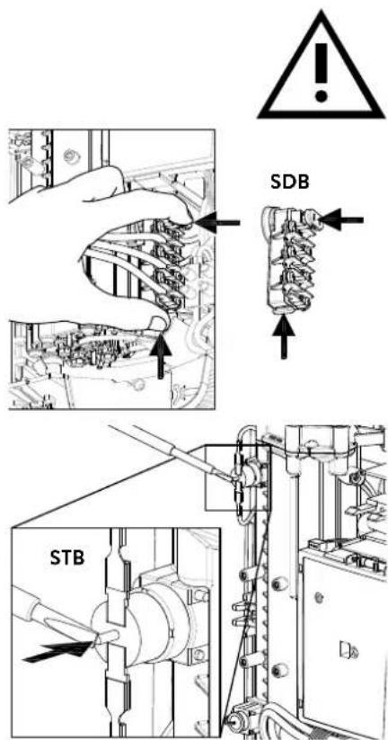
SDB STBMultiple Power System MPS®:
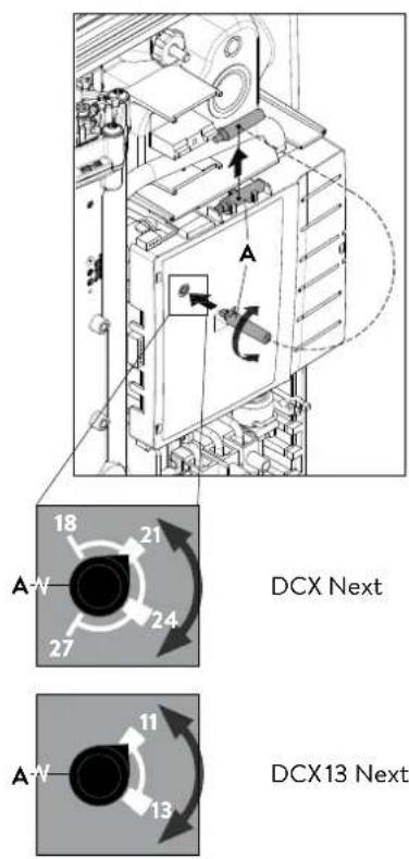
The DCX Next's capacity can be changed internally to 27 kW, 24 kW, 21 kW or 18 kW at 400 V.
The DCX 13 Next's capacity can be changed internally to 13,5 kW or 11,0 kW at 400 V.
text_image
DCX Next DCX13 NextBefore making the electrical connection, fill the mains and the appliance with water by carefully opening and closing the hot water tap in order to vent completely.
To ensure a maximum flow, remove any existing aerator from the faucet. Flush the warm and cold water pipes each at least for one minute.
After every draining (e.g. after work on the plumbing system or following repairs to the appliance), the heater must be re-vented in this way before starting it up again.
If the water heater cannot be put into operation, the temperature cut-out or the pressure cut-out may have tripped during transport. If necessary, check that the power supply is switched off and reset the cut-out.
Selection of power rating
Only by authorised specialist, otherwise lapse of guarantee!
Before first connection of the appliance to the supply voltage, select the maximum power rating.
The maximum allowable power rating at installation site depends on the local situation. It is imperative to observe all data shown in the table "Technical specifications", in particular the required cable size and fuse protection for the electrical connection. Moreover, the electrical installation must comply with the statutory regulations of the respective country and those of the local electricity supply company (Germany: DIN VDE 0100).
- Select the maximum allowable power rating depending on the local situation. To do this, take the auxiliary tool "A" from the holder on the electronics cover and turn the switch to the desired value.
| DCX Next DCX 13 Next | |||
| left stop 18 | kW first | click 11 kW | |
| first click 21 | kW second | click 13.5 kW | |
| second click | 24 kW | ||
| right stop 27 kW | |||
- Put the auxiliary tool back into the holder, connect the control panel cable to the control panel in the hood, place the hood on the appliance and fix it with the hood screw.
Note: The control panel cable must not be pinched or squeezed. - Mark the set power rating on the rating plate and slide on the faceplate from the bottom up to the stop.
- Switch on the power supply to the appliance.
- After having set the maximum allowable power rating, the heating element will be activated after approx. 10 - 30 sec of continuous water flow.
- Open the hot water tap. Check the function of the appliance.
- Explain the user how the instantaneous water heater works and hand over the operating instructions.
- Fill in the guarantee registration card and send it to the CLAGE Central Customer Service or use the online registration (see also page 18).
Note: Each time the supply voltage is switched on, the set power is indicated by alternating short and long flashes of both LEDs on the power section. If the switch is incorrectly positioned, this is indicated by continuous short flashes.
7. Initial operation

text_image
Technical diagram showing internal components of an electronic device with numbered parts labeled 1, 2, and 3.
flowchart
graph TD
    A["3"] --> B["2"]
    B --> C["1"]
    D["3"] --> E["2"]
    E --> F["1"]
Pos. OFF Pos. 3
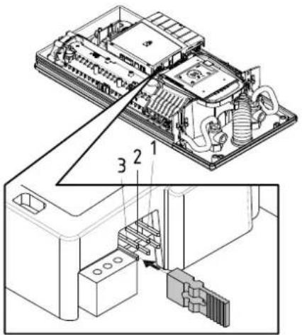
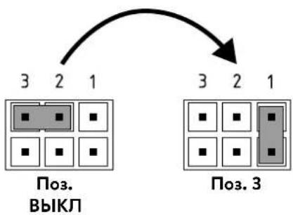
Control panel lock
The control panel can be locked internally. The temperature is fixed at the last selected value and the sensor button is deactivated.
Activation of the locking function
- Select hot water temperature
- Disconnect the appliance from the power supply (e.g. by switching off the fuses).
- Take the jumper off the power electronics and change to position "3" (see picture).
- Put the appliance into operation again.
Deactivation of the locking function
- Disconnect the appliance from the power supply (e.g. by switching off the fuses).
- Take the jumper off the power electronics and change to position "OFF" (see picture).
- Put the appliance into operation again.
8. Maintenance work
text_image
(a) closed open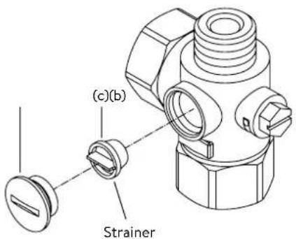
text_image
(c)(b) Strainer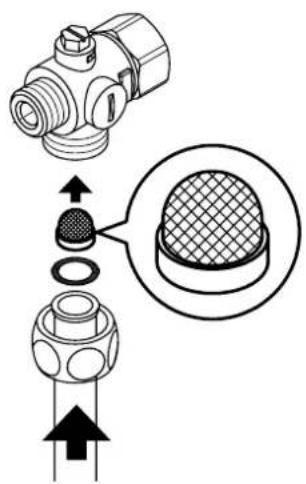
text_image
Technical diagram showing a mechanical component with an inset close-up of its cross-section, likely illustrating a machining or assembly process.Maintenance work must only be conducted by an authorised professional.
Cleaning and replacing the filter strainer
The cold water connection of this instantaneous water heater is equipped with an integrated shut-off valve and a strainer. Soiling of the strainer may reduce the warm water output. Clean or replace the strainer as follows:
- De-energize the instantaneous water heater (e.g. via deactivating the fuses) and prevent inadvertent reactivation of them.
- To open the appliance, pull down the faceplate and unscrew the main hood screw. Lift the hood carefully, remove the plug from the control panel and note the position of the plug.
- Close the shut-off valve (a) in the cold water connection piece (position "closed").
- Unscrew the screw plug (b) from the cold water connection piece and take out the strainer (c).
Note: Residual water can leak - The strainer can now be cleaned or replaced.
- After fitting of the clean strainer tighten the screw plug.
- Slowly reopen the shut-off valve in the cold water connection piece (position "open"). Ensure that there are no leakages.
- Vent the appliance by carefully opening and closing the affiliated warm water tap valve several times until air no longer emerges from the pipe.
- Connect the control panel cable to the control panel in the hood, replace the hood and tighten the hood screw.
Note: The control panel cable must not be pinched or squeezed.
Then switch on the power again (e.g. via activating the fuses).
Cleaning and replacing the filter strainer if direct connected
The cold water connection of this instantaneous water heater is equipped with a strainer. Soiling of the strainer may reduce the warm water output. Clean or replace the strainer as follows:
- De-energize the instantaneous water heater (e.g. via deactivating the fuses) and prevent inadvertent reactivation of them.
- Close the shut-off valve in the mains water supply of the instantaneous water heater.
- To open the appliance, pull down the faceplate and unscrew the main hood screw. Lift the hood carefully, remove the plug from the control panel and note the position of the plug.
- Unscrew mains water inlet from connection piece and take out the strainer. Note: Residual water can leak
- The strainer can now be cleaned or replaced.
- After refitting the clean strainer reconnect the mains water inlet to the connection piece.
- Slowly reopen the shut-off valve in the mains water supply. Ensure that there are no leakages.
- Vent the appliance by carefully opening and closing the affiliated warm water tap valve several times until air no longer emerges from the pipe.
- Connect the control panel cable to the control panel in the hood, replace the hood and tighten the hood screw.
Note: The control panel cable must not be pinched or squeezed.
Then switch on the power again (e.g. via activating the fuses).
Sommaire
text_image
Warning symbol with exclamation mark inside trianglenatural_image
3D mechanical assembly diagram showing internal components and mounting holes (no text or symbols)
natural_image
Technical illustration of VDX pipe fittings and connectors (no text or symbols)
natural_image
Product assembly of UDX connectors and wiring (no text or symbols visible)natural_image
Technical line drawing of a mechanical bracket assembly (no text or symbols)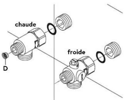
text_image
chaude D froidePose des raccords
natural_image
Technical line drawing of an electronic device interior with no visible text or symbols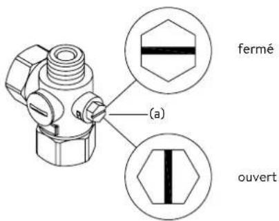
natural_image
Technical line drawing of a mechanical bracket assembly with mounting holes and internal components (no text or symbols)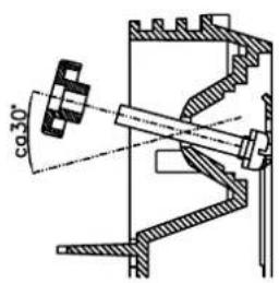
text_image
co30°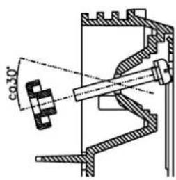
text_image
co 30°text_image
Technical diagram of an electronic device with labeled components and internal wiring, showing exploded and assembled views.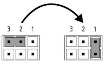
flowchart
graph TD
    A["3"] --> B["2"]
    B --> C["1"]
    D["3"] --> E["2"]
    E --> F["1"]
Pos. ARRÊT Pos. 1
text_image
180mm 60mm 8mm

text_image
Technical diagram of an electrical or mechanical device with labeled component 'S' and internal wiring pathMultiple Power System
text_image
Technical diagram of an electronic device with labeled components and internal wiring, showing exploded and assembled views.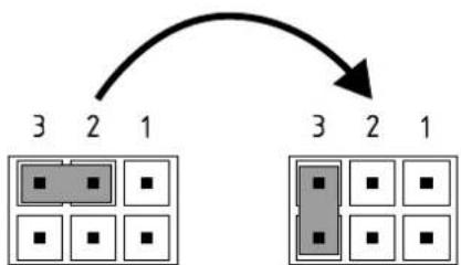
flowchart
graph TD
    A["3"] --> B["2"]
    B --> C["1"]
    C --> D["3"]
    D --> E["2"]
    E --> F["1"]
Pos. ARRÊT Pos. 3
text_image
Technical diagram showing a mechanical component with an inset close-up of a textured surface, illustrating assembly or assembly process.https://partner.clage.com/en/service/device-registration/

Instructies
text_image
Warning symbol with exclamation mark inside trianglenatural_image
3D mechanical assembly diagram showing internal components and mounting holes (no text or symbols)
natural_image
Technical illustration of VDX connectors and terminal blocks (no text or symbols)UDX
natural_image
Product assembly of flexible hose connectors and connectors (no text or symbols visible)natural_image
Technical line drawing of a mechanical bracket assembly (no text or symbols)natural_image
Technical line drawing of an electronic device interior with no visible text or symbols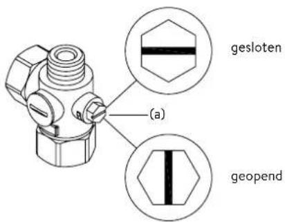
text_image
(a) gesloten geopendApparaat monteren
natural_image
Technical line drawing of a mechanical bracket assembly with mounting holes and internal components (no text or symbols)
text_image
co30°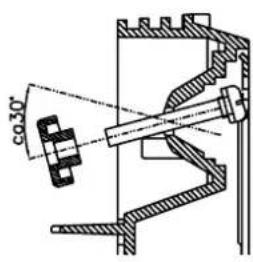
text_image
co 30°text_image
Technical diagram of an electronic device with labeled components and internal wiring, showing exploded and assembled views.text_image
180mm 60mm 8mm

text_image
Technical diagram of an electrical or mechanical device with labeled component 'S' and directional arrow indicating flow or movement.Multiple Power System MPS®:
text_image
DCX Next 18 21 A' 27 24 A' 13 11 DCX13 Nexttext_image
Technical diagram showing a computer motherboard with labeled components and an assembly process arrow indicating data routing or connection.Pos. UIT Pos. 3
Bedieningsveldvergrendeling
text_image
Technical diagram showing a mechanical component with an inset close-up of its cross-section, likely illustrating a machining or assembly process.https://partner.clage.com/en/service/device-registration/

text_image
Warning symbol with exclamation mark inside trianglenatural_image
3D mechanical assembly diagram showing internal components and mounting holes (no text or symbols)
natural_image
Product diagram of VDX connectors and wiring (no text or symbols)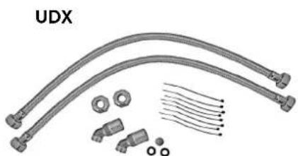
natural_image
Product assembly of UDX connectors and wiring (no text or symbols visible)A ter em conta:
• p. ex. VDE 0100
• EN 806
natural_image
Technical line drawing of a mechanical bracket assembly (no text or symbols)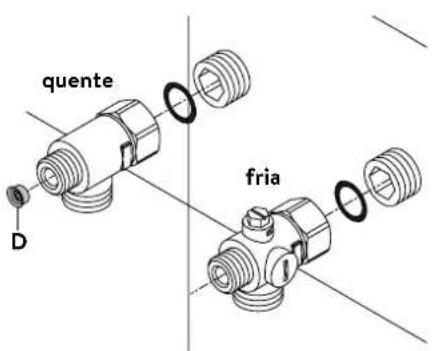
text_image
quente D frianatural_image
Technical line drawing of an electronic device interior with no visible text or symbols
text_image
fechado (a) abertonatural_image
Technical line drawing of a mechanical bracket assembly with mounting holes and internal components (no text or symbols)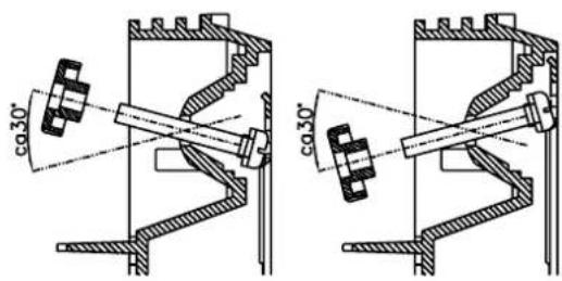
text_image
ca30° ca30°text_image
Technical diagram of an electronic device with labeled components and internal wiring, showing exploded and assembled views.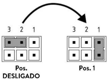
flowchart
graph TD
    A["Pos. 1"] --> B["3"]
    A --> C["2"]
    A --> D["1"]
    E["Pos. DESLIGADO"] --> F["3"]
    E --> G["2"]
    E --> H["1"]
text_image
180mm 60mm 8mm
text_image
Technical diagram of an electrical or mechanical device with labeled component 'S' and internal wiring pathMultiple Power System MPS®:
text_image
DCX Next DCX13 Nexttext_image
Technical diagram of an electronic device with labeled components and internal wiring, showing exploded and assembled views.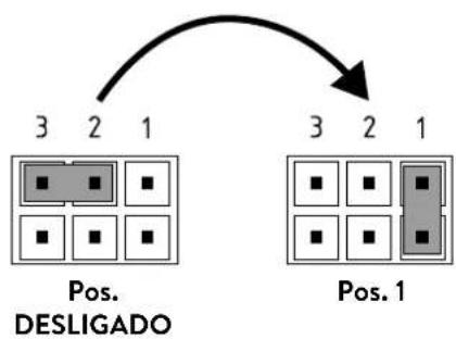
flowchart
graph TD
    A["Pos. DESLIGADO"] --> B["3 2 1"]
    C["Pos. 1"] --> D["3 2 1"]
text_image
Technical diagram showing a mechanical component with an inset close-up of its cross-section, labeled in Chinese.https://partner.clage.com/en/service/device-registration/

text_image
Warning symbol with exclamation mark inside trianglenatural_image
3D mechanical assembly diagram showing internal components and mounting holes (no text or symbols)
natural_image
Technical illustration of VDX pipe fittings and connectors (no text or symbols)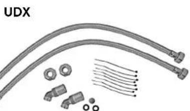
natural_image
Product diagram of UDX connectors and wiring components (no text or symbols)A tener en cuenta:
natural_image
Technical line drawing of a mechanical bracket assembly (no text or symbols)natural_image
Technical line drawing of an internal electronic device with visible components and wiring (no text or symbols)Montar el equipo
natural_image
Technical line drawing of a mechanical bracket assembly with no visible text or symbols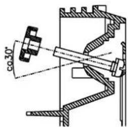
text_image
co30°
text_image
φ30°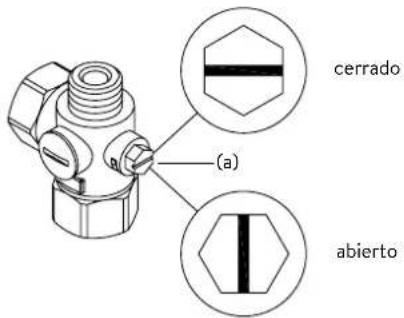
text_image
Technical diagram of an electronic device with labeled components and internal wiring, showing exploded and assembled views.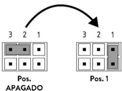
flowchart
graph TD
    A["Pos. 3"] --> B["2"]
    B --> C["1"]
    D["Pos. 2"] --> E["3"]
    E --> F["2"]
    F --> G["1"]
    H["Pos. 1"] --> I["3"]
    I --> J["2"]
    J --> K["1"]
text_image
180mm 60mm 8mm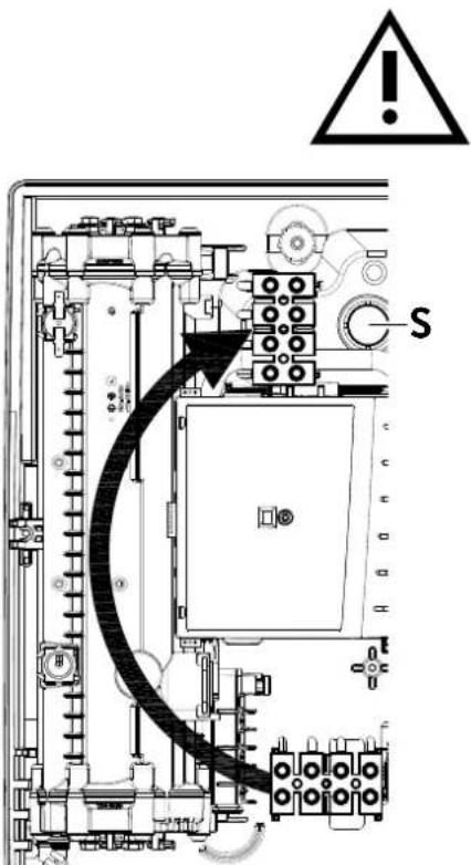
text_image
Technical diagram of an electrical enclosure with warning symbol and labeled component 'S'Multiple Power System MPS®:
text_image
DCX Next DCX13 Nexttext_image
Technical diagram of an electronic device with labeled components and internal wiring, showing exploded and assembled views.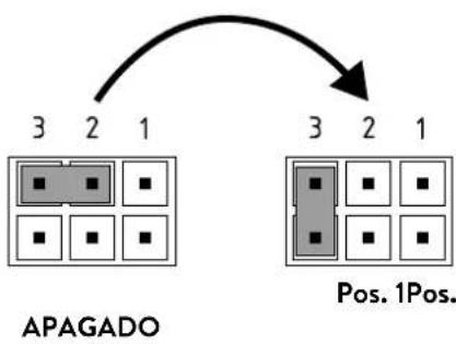
flowchart
graph TD
    A["3 2 1"] --> B["APAGADO"]
    C["3 2 1"] --> D["Pos. 1Pos."]
text_image
(c)(b) Tamiz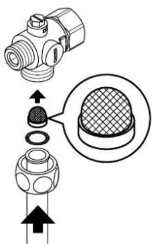
text_image
Technical diagram showing a mechanical component with an inset close-up of a textured surface, illustrating assembly or assembly process.text_image
Warning symbol with exclamation mark inside trianglenatural_image
3D mechanical assembly diagram showing internal components and mounting holes (no text or symbols)
natural_image
Technical illustration of VDX pipe fittings and connectors (no text or symbols)UDX

natural_image
Product assembly of flexible hose connectors and connectors (no text or symbols visible)natural_image
Technical line drawing of a mechanical bracket assembly (no text or symbols)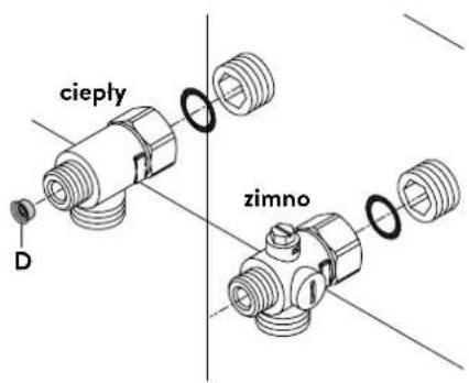
text_image
cieply D zimnonatural_image
Technical line drawing of an internal electronic device with visible components and wiring (no text or symbols)Montaż urządzenia
natural_image
Technical line drawing of a mechanical component with internal structure and directional arrows (no text or symbols)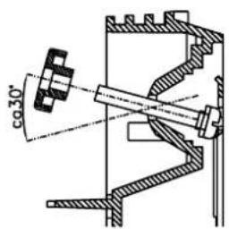
text_image
co30°
text_image
co 30°
text_image
Technical diagram of an electronic device with labeled components and internal wiring, showing exploded and assembled views.text_image
180mm 60mm 8mm

text_image
Technical diagram of an electrical or mechanical device with labeled component 'S' and internal wiring pathMultiple Power System MPS®:
text_image
A-V 11 13 DCX13 Nexttext_image
Technical diagram of an electronic device with labeled components and internal wiring, showing exploded and assembled views.text_image
Technical diagram showing a mechanical component with cross-sectional view and directional arrows indicating assembly or assembly steps.text_image
Warning symbol with exclamation mark inside trianglenatural_image
3D mechanical assembly diagram showing a frame with internal grid structure and mounting holes (no text or symbols)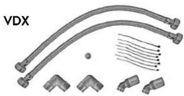
natural_image
Technical illustration of VDX connectors and wiring components (no text or symbols)UDX
natural_image
Product assembly of flexible hose connectors and connectors (no text or symbols visible)natural_image
Technical line drawing of a mechanical bracket assembly (no text or symbols)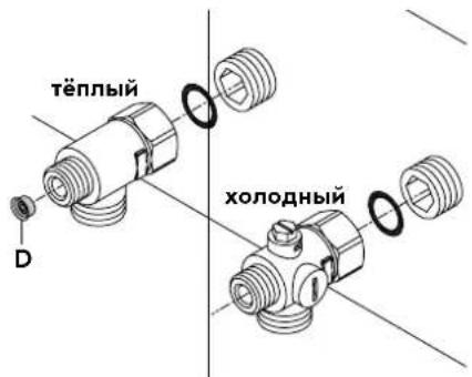
natural_image
Technical line drawing of a mechanical assembly with no visible text or symbolsМонтаж нагревателя
natural_image
Technical line drawing of a mechanical bracket assembly (no text or symbols)
text_image
co 30°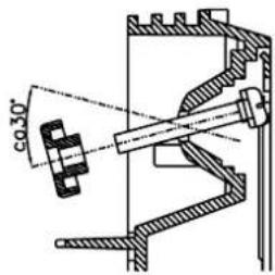
text_image
co.30°
text_image
Technical diagram of an electronic device with labeled components and internal wiring, showing exploded and assembled views.text_image
180mm 60mm 8mm
text_image
Technical diagram of an electrical or mechanical device with labeled component 'S' and internal wiring connectionsMultiple Power System MPS®:
text_image
A-V 11 13 DCX13 Nexttext_image
Technical diagram of an electronic device with labeled components and internal wiring, showing exploded and assembled views.
flowchart
graph TD
    A["3"] --> B["2"]
    B --> C["1"]
    D["Poz. 3"] --> E["3"]
    E --> F["2"]
    F --> G["1"]
    style D fill:#ccc,stroke:#333
    style E fill:#ccc,stroke:#333
    style F fill:#ccc,stroke:#333
text_image
Technical diagram showing a mechanical component with an inset close-up of a textured surface, illustrating assembly or assembly process.https://partner.clage.com/en/service/device-registration/

Návod k obsluze
text_image
Warning symbol with exclamation mark inside trianglenatural_image
3D mechanical assembly diagram showing internal components and mounting holes (no text or symbols)
natural_image
Pure electrical circuit lines without any symbols
natural_image
Product diagram of UDX cable connectors and connector components (no text or symbols)natural_image
Technical line drawing of a mechanical bracket assembly (no text or symbols)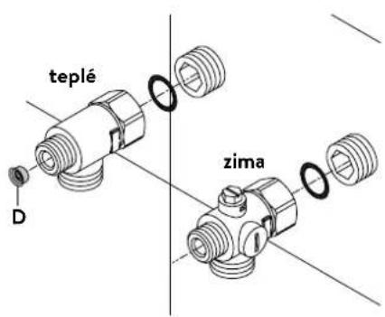
text_image
teplé D zimanatural_image
Technical line drawing of an electronic device interior with no visible text or symbolsMontáž prístroje
natural_image
Technical line drawing of a mechanical bracket assembly (no text or symbols)
text_image
φ30°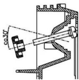
text_image
co 30°text_image
Technical diagram of an electronic device with labeled components and internal wiring, showing exploded and assembled views.text_image
180mm 60mm 8mm
text_image
Technical diagram of an electrical or mechanical device with labeled component 'S' and internal wiring connectionsMultiple Power System MPS®:
text_image
DCX Next DCX13 Nexttext_image
Technical diagram of an electronic device with labeled components and internal wiring, showing exploded and assembled views.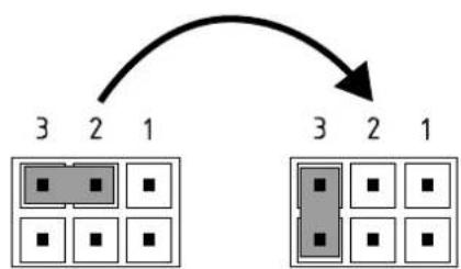
flowchart
graph TD
    A["3"] --> B["2"]
    B --> C["1"]
    D["3"] --> E["2"]
    E --> F["1"]
Pol. VYP Pol. 3
text_image
Technical diagram showing a mechanical component with an inset close-up of its cross-section, likely illustrating a machining or assembly process.https://partner.clage.com/en/service/device-registration/

Návod na použitie
text_image
Warning symbol with exclamation mark inside trianglenatural_image
3D mechanical assembly diagram showing internal components and mounting holes (no text or symbols)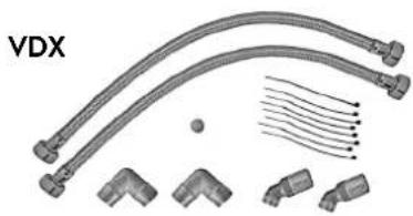
natural_image
Product diagram of VDX connectors and wiring (no text or symbols)
natural_image
Product diagram of UDX connectors and wiring components (no text or symbols)Príslušenstvo k montáži
natural_image
Technical line drawing of a mechanical bracket assembly (no text or symbols)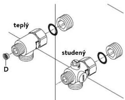
natural_image
Technical line drawing of an electronic device interior with no visible text or symbolsNamontovanie zariadenia
natural_image
Technical line drawing of a mechanical bracket assembly (no text or symbols)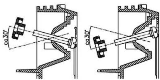
text_image
co.30° co.30°text_image
Technical diagram of an electronic device with labeled components and internal wiring, showing exploded and assembled views.
flowchart
graph TD
    A["3"] --> B["2"]
    B --> C["1"]
    D["3"] --> E["2"]
    E --> F["1"]
Pos. AUS Pos. 1
Smie vykonat'iba odborník!
Musí sa dodržiavat:
- napr. VDE 0100
- Ustanovenia miestneho elektrorozvodného a vodárenského podniku
- Technické údaje na typovom štítku
- Pripojte zariadenie na ochranný vodič!
text_image
180mm 60mm 8mm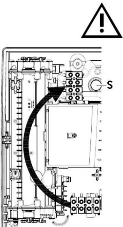
text_image
Technical diagram of an electrical switchgear with warning symbol and labeled component 'S'Multiple Power System MPS®:
text_image
DCX Next DCX13 Nexttext_image
Technical diagram of a computer motherboard with labeled components and exploded view

flowchart
graph TD
    A["3"] --> B["2"]
    B --> C["1"]
    D["3"] --> E["2"]
    E --> F["1"]
    G["3"] --> H["2"]
    H --> I["1"]
Poz. VYP Poz. 3
text_image
(c)(b) Sito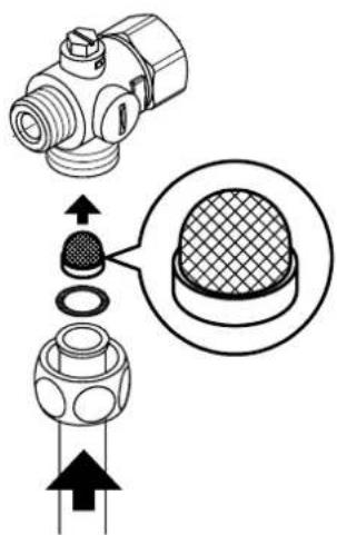
text_image
Technical diagram showing a mechanical component with cross-sectional view and directional arrows indicating assembly or assembly process.https://partner.clage.com/en/service/device-registration/

text_image
Warning symbol with exclamation mark inside trianglenatural_image
3D mechanical assembly diagram showing internal components and mounting holes (no text or symbols)
natural_image
Product diagram of VDX connectors and wiring (no text or symbols)
natural_image
Product diagram of UDX connectors and wiring components (no text or symbols)natural_image
Technical line drawing of a mechanical bracket assembly (no text or symbols)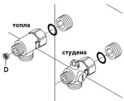
text_image
топла D студенаnatural_image
Technical line drawing of an electronic device interior with no visible text or symbols
natural_image
Technical line drawing of a mechanical bracket assembly (no text or symbols)
text_image
co 30°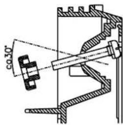
text_image
co 30°text_image
Technical diagram of an electronic device with labeled components and internal wiring, showing exploded and assembled views.text_image
180mm 60mm 8mm

text_image
Technical diagram of an electrical or mechanical device with labeled component 'S' and internal wiring pathMultiple Power System MPS®:
text_image
A-V 11 13 DCX13 Nexttext_image
Technical diagram of an electronic device with labeled components and internal wiring, showing exploded and assembled views.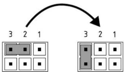
flowchart
graph TD
    A["3"] --> B["2"]
    B --> C["1"]
    D["3"] --> E["2"]
    E --> F["1"]
Поз.
ИЗКЛ.
Поз.1
text_image
Technical diagram showing a mechanical component with an inset close-up of a textured surface, illustrating assembly or assembly process.https://partner.clage.com/en/service/device-registration/

Uputstvo za upotrebu
Napomena: Priložene sigurnosne napomene pažljivo i potpuno pročitati pre instalacije, puštanja u rad i korišćenja kao i dalje postupanje, a poštovati i predviđenu namenu!
1. Opsi uređaja

text_image
COMFORT 42° 38° 40° 35° 55° ECO HOT CLAGEE-komfort protočni bojleri DCX Next / DCX 13 Next su elektronski kontrolisani protočni bojleri, otporni na pritisak, za decentralizovano napajanje vodom jedne ili više slavina.
Elektronika reguliše potrošnju energije u zavisnosti od odabrane izlazne temperature, postojeće ulazne temperature i količine protoka, kako bi u stepen precizno bila postignuta i konstantno održavana podešena temperatura čak i prikom oscilacija pritiska. Izlazna temperatura se podešava preko središnjeg senzorskog dugmeta na 35 °C, 38 °C, 42 °C, 48 °C ili 55 °C.
Kod hladne ulazne temperature i velike količine protoka moguće je da ne bude dostignuta prethodno podešena izlazna temperatura usled prekoračenja ograničenja snage. U tom slučaju se smanjivanjem količine tople vode na slavini povećava izlazna temperatura.
Protočni bojler se može koristiti u kombinaciji sa eksternim relejem za rasterećenje za elektronski kontrolisane protočne bojlere (za detalje vidi uputstvo za montažu).
text_image
Warning symbol with exclamation mark inside trianglePopravke može da obavlja samo specijalizovani servis.
Ukoliko pomoću ove tabele ne možete da otklonite grešku uredaja, obratite se korisničkom servisu. Pripremite podatke sa tipske pločice uredaja!
Trimaran d.o.o.
Mihajla Pupina 17/3 smun
11185 Beograd
Srbija
Telefon: +381 11 4051 350
natural_image
3D mechanical assembly diagram showing internal components and mounting holes (no text or symbols)
natural_image
Technical illustration of VDX pipe fittings and connectors (no text or symbols)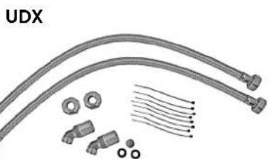
natural_image
Product assembly diagram showing UDX connectors, bolts, and wire-like components (no text or symbols)Set cevi VDX
(art. br. 34120) - RDX / RDX 3 je neophodan! -
Pomoću ovog seta za montažu moguće je montirati protočni bojler kada priključci za vodu ispod uređaja izlaze iz zida pomereno ili im je zamenjen položaj ili se u odnosu na uređaj nalaze bočno na zidu. Električni priključak može da izlazi iz zida na bilo kom mestu ispod uređaja, odn. da se nalazi na zidu.
Set cevi UDX
(art. br. 34110) - RDX / RDX 3 je neophodan! -
Pomoću ovog seta za montažu moguće je montirati protočni bojler kada se priključci za vodu završavaju iznad uređaja. Električni priključak može da izlazi iz zida na bilo kom mestu ispod uređaja, odn. da se nalazi na zidu.
4. Instalacija

text_image
12 G 1/2" 100natural_image
Technical line drawing of a mechanical bracket assembly (no text or symbols)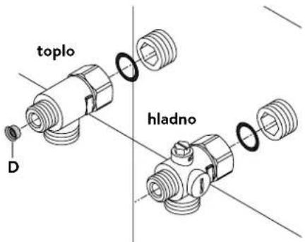
text_image
toplo hladno DInstalacija priključnih fitinga za vodu
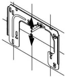
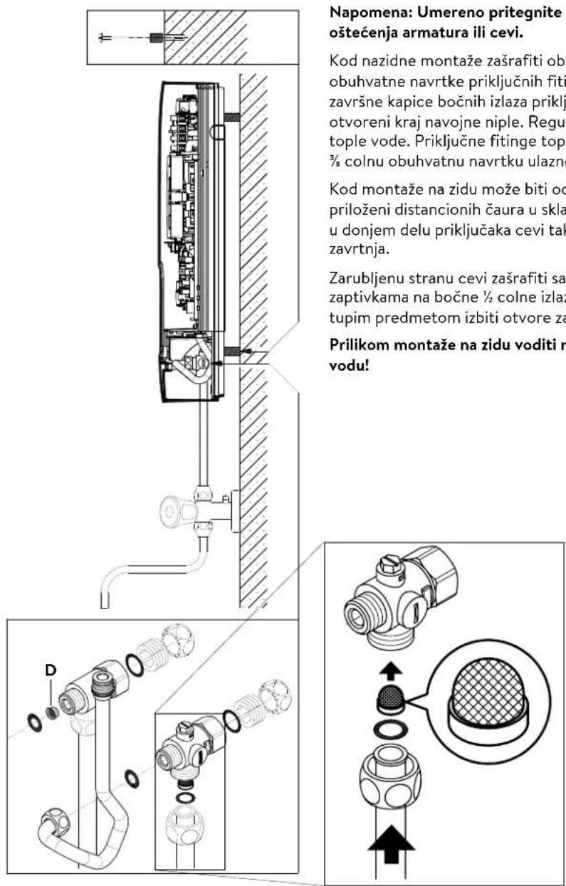
Napomena: Umereno pritegnite obuhvatne navrtke da obezbedite zaptivanje bez oštećenja armatura ili cevi.
- U skladu sa slikom zašrafite priključni fiting za hladnu vodu sa obuhvatnom navrtkom i zaptivkom od ½ cola na priključak za hladnu vodu.
- U skladu sa slikom zašrafite priključni fiting za toplu vodu sa obuhvatnom navrtkom i zaptivkom od ½ cola na priključak za toplu vodu.
- Uvucite regulator količine protoka »D« u priključni komad tople vode. O-prsten mora da bude vidljiv.
4. Instalacija
natural_image
Technical line drawing of an electronic device interior with no visible text or symbolsSR

text_image
zatvoreno (a) otvorenoMontaža uređaja
- Moguće je da se kabl za dovod struje nalazi u gornjem delu uredaja ili na zidu. U tom slučaju prvo pratite korake jedan do tri iz opisa »Električni priključak odozgo« iz poglavlja »Električni priključak«.
- Postavite uređaj na zidni držač tako da navojna šipka zidnog držača ulazi u za to predviđeni otvor na uređaju. Pažljivim savijanjem navojne šipke zidnog držača po potrebi možete da izvršite manje korekture. Priključne cevi za vodu uređaja moraju da se ušrafe bez primene sile.
- Zašrafite plastične nareckane navrtke na navojnu šipku zidnog držača.
- Zašrafite obe % colne obuhvatne navrtke priključnih cevi za vodu uređaja sa % colnom zapivkom na instalirane priključne fitinge.
natural_image
Technical line drawing of a mechanical bracket assembly (no text or symbols)
text_image
φ30°
text_image
co 30°-
Otvorite dovod vode i okrenite zaporni ventil (a) u priključnom fitingu hladne vode polako na (položaj »otvoreno«). Proverite sve spojeve na curenje.
-
Zatim više puta otvorite i zatvorite odgovarajuću slavinu za toplu vodu sve dok iz cevi ne prestane da izlazi vazduh i dok protočni bojler ne bude odzračen.
5. Montaža na zidu
text_image
Napomena: Umereno pritegnite oštećenja armatura ili cevi. Kod nazidne montaže zašrafiti obu obuhvatne navrtke priključnih fiti završne kapice bočnih izlaza priklj otvoreni kraj navojne niple. Regul tople vode. Priključne fitinge topl 3/8 colnu obuhvatnu navrtku ulazne Kod montaže na zidu može biti od priloženi distancionih čaura u skla u donjem delu priključaka cevi tak zavrtnja. Zarubljenu stranu cevi zašrafiti sa zaptivkama na bočne ½ colne izlaz tupim predmetom izbiti otvore za Prilikom montaže na zidu voditi ra vodu!Napomena: Umereno pritegnite obuhvatne navrtke da obezbedite zaptivanje bez oštećenja armatura ili cevi.
Kod nazidne montaže zašrafiti obe ½ colne navojne niple i ½ colne zaptivke na ½ colne obuhvatne navrtke priključnih fitinga za toplu i hladnu vodu. Demontirati obe ½ colne završne kapice bočnih izlaza priključnih fitinga za toplu i hladnu vodu i zašrafiti ih na otvoreni kraj navojne niple. Regulator količine protoka »D« uvucite u priključni fiting tople vode. Priključne fitinge tople i hladne vode zašrafiti sa ¾ colnim zaptivkamana ¾ colnu obuhvatnu navrtku ulazne i izlazne cevi uređaja.
Kod montaže na zidu može biti od pomoći da se uređaj montira na rastojanju pomoću priloženi distancionih čaura u skladu sa crtežom pored. Oba otvora za pričvršćivanje u donjem delu priključaka cevi takođe propisno fiksirati pomoću tiplova od 6 mm i zavrtnja.
Zarubljenu stranu cevi zašrafiti sa ½ colnim obuhvatnim navrtkama i ½ colnim zaptivkama na bočne ½ colne izlaze priključnih fitinga za toplu i hladnu vodu. Zatim tupim predmetom izbiti otvore za cevi na haubi.
Prilikom montaže na zidu voditi računa: Postavite sito u priključni fiting za hladnu vodu!
6. Električní priključak
Šema povezivanja
text_image
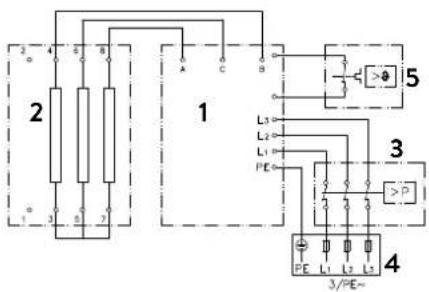
2 4 6 8 1 A C 5 L3 L2 L1 PE 3 P 4 3/PE~- Elektronika
- Grejač
- Sigurnosni presostat SDB
- Priključna letva
- Sigurnosni limitator temperature STB
Samo za stručno lice!
Imajte u vidu:
- npr. VDE 0100
- Propise lokalnih elektrodistributivnih preduzeća i vodovoda
- Tehničke podatke i podatke sa tipske pločice
- Povežite uredaj na zaštitni provodnik!
text_image
Technical diagram of an electronic device with labeled components and internal wiring, showing exploded and assembled views.text_image
Technical diagram showing mechanical assembly with labeled component A and directional arrow indicating motion or flowtext_image
180mm 60mm 8mm

text_image
Technical diagram of an electrical enclosure with labeled component 'S' and internal wiring pathElektrični priključak odozgo
Uverite se da je napajanje strujom isključeno pre povezivanja uređaja na električnu mrežu!
- Otvorite postojeće mesto za probijanje otvora na gornjem delu uređaja (S) po perforaciji snažnim pritiskom tupim alatom (npr. odvijačem). Kada je električni priključni kabl postavljen na zidu, dodatno otvorite otvor na desnoj strani donjeg dela uređaja.
- Isecite rukavac iz kesice sa priborom u skladu sa poprečnim presekom dovodnog kabla. Pri tom dimenzionirajte otvor rukavca nešto manje od poprečnog preseka priključnog kabla da bi ste postigli optimalnu zaštitu od vode. Prilagodite rukavac u skladu sa otvorom. Obavezno koristiti zaštitni rukvac!
- Skinite omotač priključnog kavla tako da rukavac ulazi u unutrašnjost uređaja. Uzimte pripremljeni uređaj u jednu ruku a drugom rukom provucite kabl kroz rukavac.
- Postavite uređaj na zidni držač, provucite navojnu šipku zidnog držača kroz za to predviđeni otvor na uređaju i fiksirajte uređaj.
- Oslobodite zavrtanj za pričvršćivanje priključne kleme. Premestite priključnu klemu na gornju stopu i ponovo je pričvrstite.
- Ogolite pojedinačne žice priključnog kabla i povežite ih na priključne kleme u skladu sa elektro šemom. Povežite uređaj na zaštitni provodnik.
Multiple Power System MPS®:
DCX Next: Nazivna snaga iznosi 27 kW pri 400 V i može se interno promeniti na 24 kW, 21 kW ili 18 kW!
DCX 13 Next: Nazivna snaga iznosi 13,5 kW pri 400 V i može se interno pro- meniti na 11 kW
text_image
DCX Next DCX13 NextPre električnog povezivanja napunite vodom vodovodnu mrežu i uređaj kroz laganih otvaranja i zatvaranja slavine za toplu vodu i time je potpuno odzračite.
U tom cilju izvadite event. postavljene regulatore mlaza (perlatore) iz armature da bi ste obezbedili maksimalan protok. Isperite instalaciju tople i hladne vode u trajanju od najmanje jednog minuta.
Uređaj je potrebno ponovo odzračiti posle svakog pražnjenja (npr. posle radova na vodovodnoj instalaciji, zbog opasnosti od smrzavanja ili posle popravke uredaja) i pre ponovnog puštanja u rad.
Ukoliko se protočni bojler ne može pustiti u rad, proverite da li su se usled transporta aktivirali sigurnosni limitator temperature (STB) ili sigurnosni presostat (SDB). Uverite se da li je uređaj pod naponom i po potrebi resetujte sigurnosti prekidač.
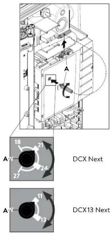
Promena snage
Ovo može da obavlja samo ovlašćeno stručno lice, u suprotnom dolazi do gašenja garancije!
Prilikom prvog uključivanja naponskog napajanja mora biti podešena maksimalna snaga uređaja.
Maksimalna moguća snaga zavisi od instalacije. Obavezno poštujte podatke iz tabele »Tehnički podaci«, a posebno neophodan poprečni presek električnog priključnog kabla i osigurača. Dodatno poštujte propise standarda DIN VDE 0100.
- Podesite maksimalnu snagu uređaja u zavisnosti od instalacije. U tom cilju izvadi- te pomagalo »A« iz držača na poklopcu elektronike i okrenite prekidač na željenu vrednost.
| DCX Next DCX13 | Next | ||
| Graničnik levo 18 | kW Uklopna tačka 1 11 kW | ||
| Uklopna tačka 1 21 | kW Uklopna tačka 2 13,5 | kW | |
| Uklopna tačka 2 24 kW | |||
| Graničnik desno 27 kW | |||
- Ponovo postavite pomagalo u držač, priključite kabl komandnog panela na komandni panel u haubi, postavite haubu na uredaj i fiksirajte zavrtnjem za haubu. Napomena: Kabl komandnog panela ne sme da bude priklješten ili prignječen.
- Obeležite podešenu snagu na tipskoj pločici.
- Uključite dovod struje ka uređaju.
- Nakon podešavanja maksimalne snage uređaja, grejanje vode se aktivira posle pribl. 10 – 30 sekundi kontinuiranog protoka vode.
- Otvorite ventil za ispušanje tople vode. Proverite funkcionisanje protočnog bojlera.
- Upoznajte korisnika sa upotrebom i predajte mu uputstvo za upotrebu.
- Popunite registracionu karticu i pošaljite je korisničkom servisu ili registrujte vaš uređaj online na našoj internet prezentaciji (vidi takođe i stranu 187).
Napomena: Istovremeno prebacivanje napona napajanja određuje se produženim tokom i treperi LED na kontrolnoj tabli. Nepravilno je postavljen na prekidaču za napajanje i povezan neprekidnim kursevima.
text_image
Technical diagram of a computer motherboard with labeled components and exploded view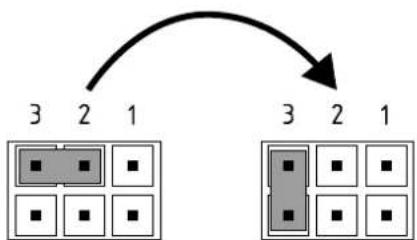
flowchart
graph TD
    A["3"] --> B["2"]
    B --> C["1"]
    D["3"] --> E["2"]
    E --> F["1"]
    G["3"] --> H["2"]
    H --> I["1"]
Poz. ISKLJ Poz. 3
Blokada rukovanja
text_image
(c)(b) Cjedilo
text_image
Technical diagram showing a mechanical component with an inset close-up of a textured surface, illustrating assembly or assembly process.Radove na održavanju može da obavlja samo ovlašćeni specijalizovani servis.