450-50 CT4 - Compressor Aerotec - Free user manual and instructions
Find the device manual for free 450-50 CT4 Aerotec in PDF.
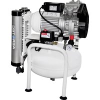
| Product type | Air compressor |
| Brand | Aerotec |
| Model | 450-50 CT4 |
| Drive type | Direct |
| Power supply | Single-phase 230 V or three-phase 400 V depending on version |
| Maximum pressure | 10 bar |
| Tank capacity | 50 liters |
| Lubrication type | Lubricated |
| Start | Automatic via pressure switch |
| Thermal protection | Yes |
| Safety valve | Yes |
| Pressure regulator | Yes |
| Pressure gauge | Tank and outlet |
| Suction filter | Yes, clean every 100 hours |
| Oil change | First oil change at 100 h, then every 300 h |
| Ambient temperature | +5 °C to +40 °C |
| Safety distance | Minimum 3 meters |
| Use | Compressed air only |
| Duty cycle | Intermittent (e.g., S3-25) |
| Transport | Do not transport under pressure |
| Safety | Safety goggles mandatory, risk of burns, automatic restart |
| Maintenance | Clean filter, drain condensation and oil |
| Warranty | Does not cover wear parts |
Frequently Asked Questions - 450-50 CT4 Aerotec
User questions about 450-50 CT4 Aerotec
0 question about this device. Answer the ones you know or ask your own.
Ask a new question about this device
Download the instructions for your Compressor in PDF format for free! Find your manual 450-50 CT4 - Aerotec and take your electronic device back in hand. On this page are published all the documents necessary for the use of your device. 450-50 CT4 by Aerotec.
USER MANUAL 450-50 CT4 Aerotec
Instructions for use manual
Manuel utilisateur
Betriebsanleitung
natural_image
Close-up of a car grille with mesh pattern and circular cutouts (no text or symbols visible)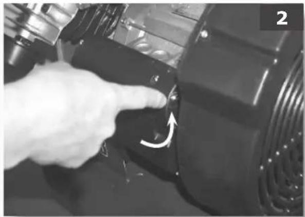
natural_image
Close-up of a hand pressing a button on a black industrial component, no visible text or symbols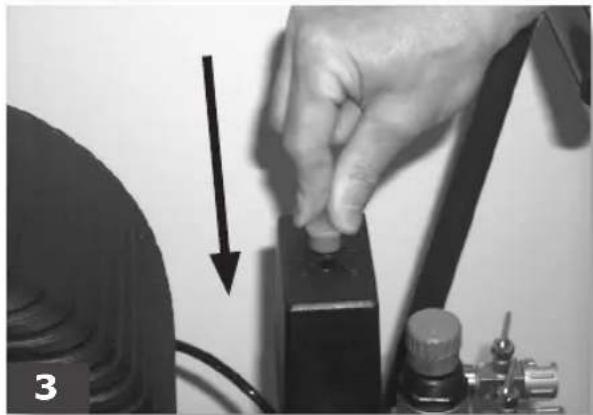
natural_image
Close-up of a hand adjusting a black mechanical component with a downward arrow, no visible text or symbols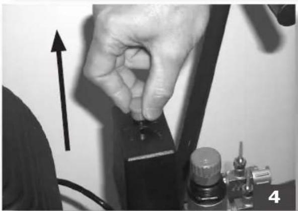
natural_image
Close-up of a hand pressing down on a mechanical component with an upward arrow indicator (no text or symbols visible)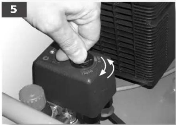
natural_image
Close-up of a hand pressing a black industrial control knob with a white arrow indicating rotation (no text or symbols visible)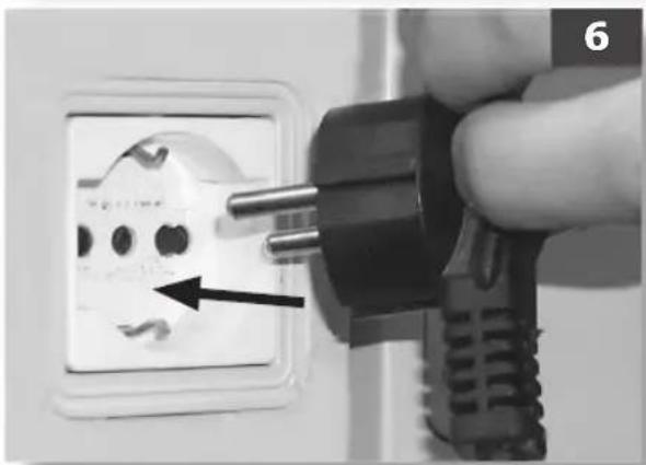
natural_image
Close-up of a hand inserting a black plastic plug into an electrical socket, with a black arrow pointing to the socket (no text or symbols visible)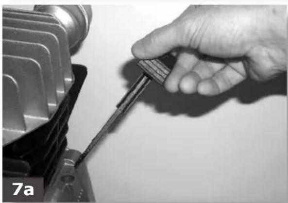
natural_image
Close-up of a hand holding a screwdriver inserted into a mechanical component (no visible text or symbols)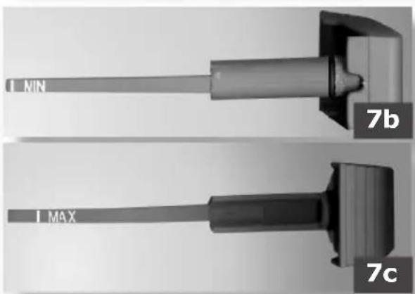
text_image
MIN 7b MAX 7c


text_image
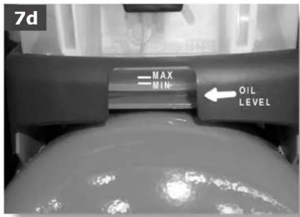
7d MAX MIN- OIL LEVEL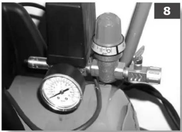
natural_image
Close-up of a pressure regulator with gauges and tubing (no visible text or symbols)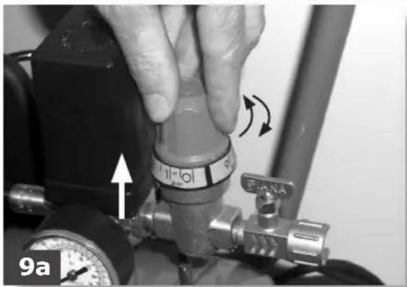
natural_image
Close-up of a hand adjusting a pressure regulator valve with directional arrows (no text or symbols visible)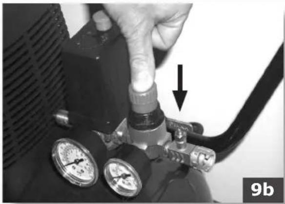
natural_image
Close-up of a hand adjusting a pressure regulator valve with two gauges, no visible text or symbols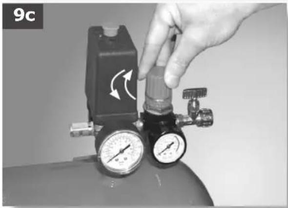
natural_image
Close-up of a gas regulator with pressure gauges and a hand adjusting the valve (no visible text or symbols)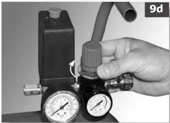
natural_image
Hand holding a pressure regulator with gauges and tubing, no visible text or symbols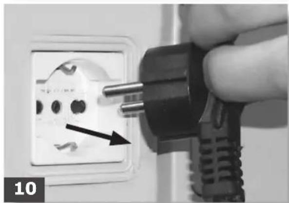
natural_image
Close-up of a hand inserting a black plastic plug into an open electrical socket, with a black arrow pointing to the socket (no text or symbols visible)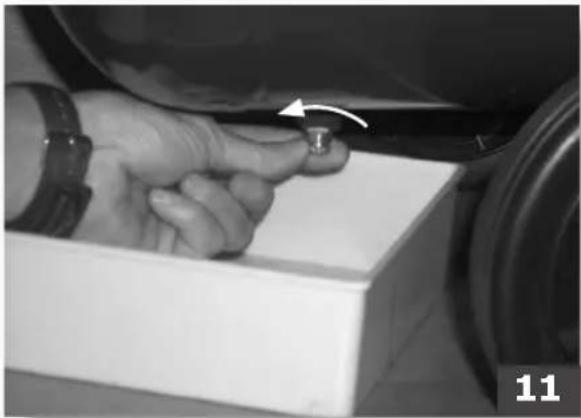
natural_image
Close-up of a hand adjusting a small mechanical component with an arrow indicating rotation (no text or symbols visible)


natural_image
Close-up of a hand using a screwdriver to adjust or install a component, with no visible text or symbols.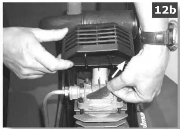
natural_image
Close-up of hands operating a mechanical pump or compressor unit with a valve and hose (no visible text or symbols)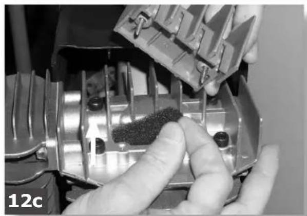
natural_image
Close-up of hands assembling a mechanical component with a textured surface, no visible text or symbols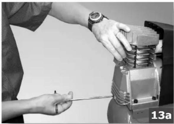
natural_image
Close-up of hands using a screwdriver to adjust or install a mechanical component (no visible text or symbols)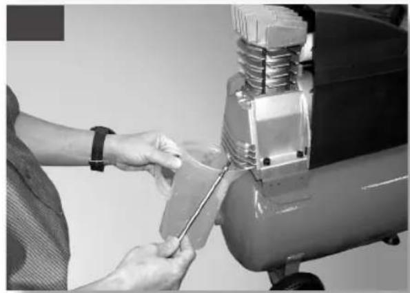
natural_image
Person using a tool to adjust or install a mechanical component with a spring and cylinder (no visible text or symbols)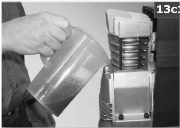
natural_image
Person pouring liquid into a mechanical component (no visible text or symbols)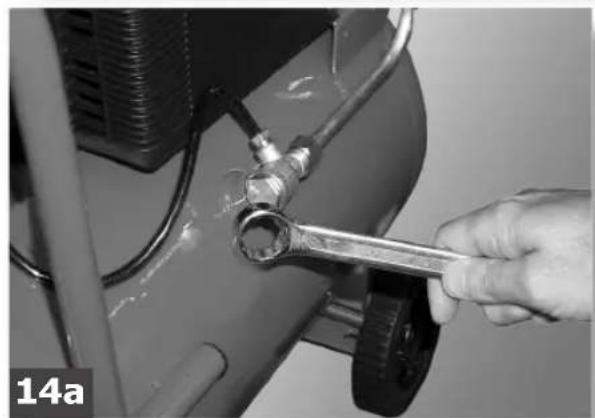
natural_image
Close-up of a hand using a wrench to adjust a mechanical component (no visible text or symbols)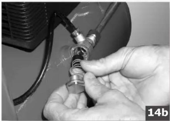
natural_image
Close-up of hands adjusting a mechanical component with a coiled cable and threaded spring (no visible text or symbols)
COMPRESSORE A TRASMISSIONE DIRETTA

Importante:
Before using the compressor, always read the instructions handbook and consult it if you have any doubts regarding compressor functioning.

Important:
Safety goggles MUST be worn when using the compressor.

Warning:
Parts of the compressor may become very hot.

Warning:
The compressor operates according to an automatic on/off cycle and may therefore restart in the case of a blackout and subsequent power-up.

Warning:
Always use sockets with a ground connection to avoid the risk of electric shock.
PRECAUTIONS
THINGS NOT TO DO
THINGS TO DO
Never direct the jet of air towards persons, animals or your body. (Always wear safety goggles to protect your eyes against flying objects that may be lifted by the jet of air).
Never direct the jet of liquids sprayed by tools connected to the compressor towards the compressor.
Never use the appliance with bare feet or wet hands or feet.
Never pull the power cable to disconnect the plug from the socket or to move the compressor.
Never leave the appliance exposed to adverse weather conditions.
Never transport the compressor with the receiver under pressure.
Do not weld or machine the receiver. In the case of faults or rusting, replace the entire receiver.
Never allow inexpert persons to use the compressor.
Keep children and animals at a distance from the work area.
Do not position flammable or nylon/fabric objects closed to and/or on the compressor.
Never clean the compressor with flammable liquids or solvents. Check that you have unplugged the compressor and clean with a damp cloth only.
The compressor must be used only for air compression. Do not use the compressor for any other type of gas.
The compressed air produced by the compressor cannot not be used for pharmaceutical, food or medical purposes except after particular treatments and cannot be used to fill the air bottles of scuba divers.
The compressor must be used in suitable environments (well ventilated with an ambient temperature of between +5°C and +40°C) and never in places affected by dust, acids, vapors, explosive or flammable gases.
Always maintain a safety distance of at least 3 meters between the compressor and the work area..
Any coloring of the plastic protection of the compressor during painting operations indicates that the distance is insufficient.
Insert the plug of the electrical cable in a socket of suitable shape, voltage and frequency complying with current regulations.
For three-phase versions have the plug fitted by a qualified electrician according to local regulations. The first time you start the compressor, check that the direction of rotation is correct and matches that indicated by the arrow on the conveyor (Fig. 1, the air must be conveyed towards the head of the compressor):
Use extension cables with a maximum length of 5 meters and with a cable cross-section of not less than 1.5 mm ^4 .
Use of extension cables of different length and cross-section and also of adapters and multiple sockets should be avoided.
Always use the handle to move the compressor. When operating, the compressor must be placed on a stable, horizontal surface to assure correct lubrication (lubricated versions).
THINGS YOU SHOULD KNOW
To avoid overheating of the electric motor, this compressor is designed for intermittent operation as indicated on the technical dataplate (for example, S3-25 means 2.5 minutes ON, 7.5 minutes OFF).
In the case of overheating, the thermal cutout of the motor trips, automatically cutting off the power when the temperature is too high. The motor restarts automatically when normal temperature conditions are restored.
On certain «V» type versions, the reset button on the terminal box of the motor must be pressed (fig. 2). To facilitate restart of the compressor, in addition to the operations indicated, it is important to return the button of the pressure switch to the OFF position and then to ON again (figures 3-4-5).
On three-phase versions, simply return the button of the pressure switch to the ON position. (fig. 4). Single-phase versions are fitted with a pressure switch equipped with a delayed closing air discharge valve which facilitates start-up of the motor. Therefore venting of air from this valve for a few seconds with the receiver empty is normal.
All the compressors are fitted with a safety valve that is tripped in the case of malfunctioning of the pressure switch in order to assure machine safety.
When fitting a tool, the flow of air in output must be switched off.
When using compressed air, you must know and comply with the safety precautions to be adopted for each type of application (inflation, pneumatic tools, painting, washing with water-based detergents only, etc.).
START-UP AND USE
Fit the wheels and foot (or the suckers according to model) following the instructions provided in the packaging.
Check that the rating data match the effective characteristics of the system (voltage and power).
Insert the plug of the power cable in a suitable socket (fig. 6) checking that the button of the pressure switch located on the compressor is in the OFF «O» position.
For lubricated models, check the oil level using the rod included in the oil fuel plug (figures 7a-7b-7c) or the sight glass (fig. 7d), and if necessary top up.
At this point, the compressor is ready for use.
Operating on the switch of the pressure switch (fig. 4), the compressor starts, pumping air into the receiver through the delivery pipe.
When the upper calibration value (set by the manufacturer) has been reached, the compressor stops, venting the excess air present in the head and in the delivery pipe through a valve located under the pressure switch.
This facilitates subsequent restart due to the absence of pressure in the head. When air is used, the compressor restarts automatically when the lower calibration value is reached (2 bar between upper and lower).
The pressure in the receiver can be checked on the gauge provided (fig. 8).
The compressor continues to operate according to this automatic cycle until the switch of the pressure switch is turned.
Always wait at least 10 seconds from when the compressor has been switched off before restarting this.
All compressors are fitted with a pressure reducer. Operating on the knob with the tap open (pulling it up and turning it in a clockwise direction to increase the pressure and in a counterclockwise direction to reduce this fig. 9a), air pressure can be regulated so as to optimize use of pneumatic tools. After setting the value required, push the knob to fasten this (fig. 9b). On some versions, the ring-nut underneath must be tightened to fasten the knob (figures 9c, 9d).
The value set can be checked on the gauge (for versions on which this is fitted) or checking the numbered notches on the knob whose values correspond to the related pressures.
Always pull out the plug and drain the receiver once you have completed your work (figures 10, 11).
MAINTENANCE
BEFORE CARRYING OUT ANY OPERATION, ALWAYS PULL OUT THE PLUG AND DRAIN THE RECEIVER COMPLETELY (figures 10-11).
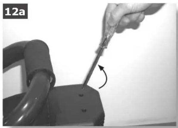
After loosening any safety screws (fig. 12a), clean the intake filter according to the type of working environment and at least every 100 hours (figures 12b, 12c). If necessary, replace the filter element (clogging of the filter reduces compressor performance and an inefficient filter causes increased wear.). For lubricated models, replace the oil after the first 100 hours of operation and every 300 hours subsequently (figures 13a, 13b, 13c). Remember to check the oil level at regular intervals.
Periodically (or after working with the compressor for more than an hour), drain the condensate that forms inside the receiver (fig. 11) due to the humidity in the air. This protects the receiver from corrosion and does not restrict its capacity.
Spent oil (lubricated models) and condensate MUST BE DISPOSED OF in accordance with environmental protection regulations and current legislation.
WARRANTY
The warranty does not cover all electrical parts and all parts that, due to their specific use, are liable to wear. The warranty envisages the manufacturer's obligation to repair or replace, at its discretion, parts acknowledged as faulty by its own technicians provided that such faults refer to the construction of the products and/or the quality of the materials (i.e. they are to be ascribed to the manufacturer) and are not caused by normal wear, negligence, incorrect or improper use of the product by the user not complying with the instructions, tampering, repairs or disassembly even only partial by persons not authorized by the manufacturer, excessive use of the machine or unsuitable applications, fortuitous events or circumstances of force majeure. All compressors with up to 100-liter receivers must be sent to the Service Center carriage free and will be returned carriage forward.
Ask your supplier for the location of your nearest Center.
The manufacturer reserves the right to make any modifications it considers necessary without prior notice.
POSSIBLE FAULTS AND RELATED PERMITTED REMEDIES
Fault Cause Remedy
| Leakage of air from the valve of the pressure switch with the compressor off. | Check valve that, due to wear or dirt on the seal, does not perform its function correctly. | Unscrew the hexagonal head of the check valve, clean the valve seat and the special rubber disk (replace if worn). Reassemble and tighten carefully (figures 14a, 14b). |
| Reduction of performance. Frequent start-up. Low pressure values. | Excessive performance request, check for any leaks from the couplings and/or pipes. Intake filter may be clogged. | Replace the seals of the fitting, clean or replace the filter. |
| The compressor stops and restarts automatically after a few minutes. In the V, 3 HP versions, it is does not start. | Tripping of the thermal cutout due to overheating of the motor. | Clean the air ducts in the conveyor. Ventilate the work area. Reset the thermal cutout. On lubricated and V type models, check oil level and quality. On V models, have the voltage checked. |
| After a few attempts to restart, the compressor stops. | Tripping of the thermal cutout due to overheating of the motor (removal of the plug with the compressor running, low power voltage). | Activate the on/off switch. Ventilate the work area. Wait a few minutes. The compressor will restart independently. On V, 3 HP models, reset the thermal cutout. Remove any power cable extensions. |
| The compressor does not stop and the safety valve is tripped. | Irregular functioning of the compressor or breakage of the pressure switch. | Remove the plug and contact the Service Center. |
F
COMPRESSEUR À TRANSMISSION DIRECTE

Important :
POSSIBLES ANOMALIES ET INTERVENTIONS ADMISES
Anomalie Cause Intervention