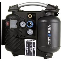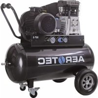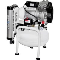
AEROMEDIC XTR 2D-25 - Compressor Aerotec - Free user manual and instructions
Find the device manual for free AEROMEDIC XTR 2D-25 Aerotec in PDF.


| Brand | Aerotec |
| Model | AEROMEDIC XTR 2D-25 |
| Type | Compressor with adsorption air dryer |
| Power supply | 220 V / 50-60 Hz (110 V version available) |
| Maximum pressure | 10 bar |
| Working pressure | 8 bar |
| Nominal air flow | 400 L/min |
| Compressor type | Oil-free |
| Duty cycle | Intermittent S3-50 (5 min run / 5 min stop) |
| Power consumption (dryer) | 17 W |
| Dryer weight | 7 kg |
| Operating temperature | -5 °C to +45 °C |
| Tank material | Steel |
| Safety | Safety valve, thermal protection, pressure switch |
| Maintenance | Filter cleaning and replacement, daily tank draining |
| Warranty | 24 months |
| Applications | Compressed air for dental, pneumatic, inflation, etc. |
| Manual language | French |
Frequently Asked Questions - AEROMEDIC XTR 2D-25 Aerotec
User questions about AEROMEDIC XTR 2D-25 Aerotec
0 question about this device. Answer the ones you know or ask your own.
Ask a new question about this device
Download the instructions for your Compressor in PDF format for free! Find your manual AEROMEDIC XTR 2D-25 - Aerotec and take your electronic device back in hand. On this page are published all the documents necessary for the use of your device. AEROMEDIC XTR 2D-25 by Aerotec.
USER MANUAL AEROMEDIC XTR 2D-25 Aerotec
natural_image
Exterior view of a white industrial air compressor unit with visible mechanical components and branding (no text or symbols on main body)• Manuale istruzioni
• Instructions for use manual
• Manuel utilisateur
• Betriebsanleitung
• Manual de instrucciones
• Manual de instruções
• Gebruiksaanwijzing
• Brugsanvisning
• Instruktionsmanual
• Käyttöohjeet
• Εγχειρίδιο οδηγιών
• Instrukcje obsługi
• Upute za upotrebu
• Navodila za uporabo
- Kezelésiútmutató
• Příručkak obsluze
• Návod na obsluhu
• Руководствопо эксплуатации
• Bruksanvisning
• Kullanma talimati
• Manual de utilizare
• Ръководство експлоатацията
• Uputstvaza upotrebu
• Instrukciju vadovélis
• Kasutamisjuhend
• Instrukciju rokasgrāmata

natural_image
Industrial air compressor unit with fan and control panel (no visible text or symbols)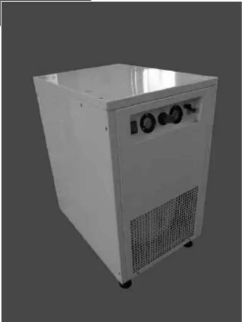
natural_image
Exterior view of a white industrial air purifier unit with control panel and ventilation grille (no visible text or symbols)| Dentalkompressoren |
| AEROMEDIC XTR 2V-25 |
| AEROMEDIC XTR 2D-25 |
| AEROMEDIC XTR 2V-50 |
| AEROMEDIC XTR 2D-50 |
| AEROMEDIC XTR 3V-25 |
| AEROMEDIC XTR 3V-50 |
| AEROMEDIC XTR 3D-50 |
| AEROMEDIC XTR 2V-30 SIL |
| AEROMEDIC XTR 2D-30 SIL |
| AEROMEDIC XTR 4V-90 |
| AEROMEDIC XTR 4V-90 HP3 |
| AEROMEDIC XTR 4D-90 |
| AEROMEDIC XTR 4D-90 HP3 |
| AEROMEDIC XTR 4D-90V |
| AEROMEDIC XTR 4V-90V - S1 - 230V |
| AEROMEDIC XTR 4D-90V - S1 - 230V |
| AEROMEDIC XTR 4V-90V - S1 - 400V |
| AEROMEDIC XTR 4D-90V - S1 - 400V |
| AEROMEDIC XTR 4V-270 |
| AEROMEDIC XTR 4D-270 |
| AEROMEDIC XTR 8V-270 mit DSS |
| AEROMEDIC XTR 8D-270 mit DSS |
| AEROMEDIC XTR 8V-270 mit MPS |
| AEROMEDIC XTR 8D-270 mit MPS |
| AEROMEDIC XTR 12V-270 |
| AEROMEDIC XTR 12D-270 |
text_image
1 ON OFF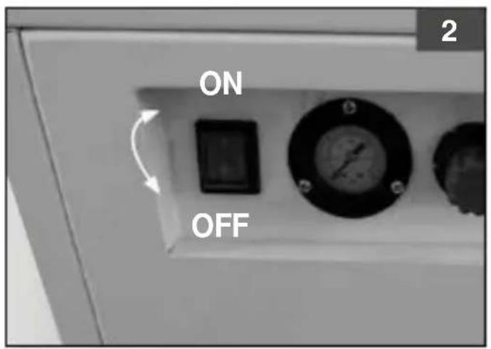
text_image
ON OFF 2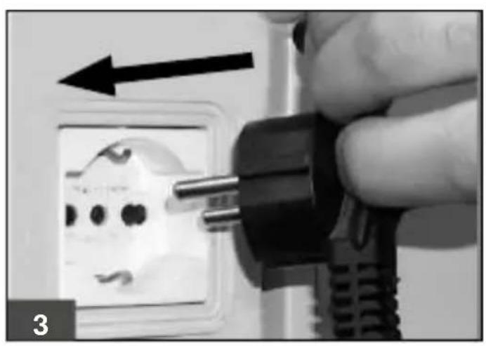
natural_image
Close-up of a hand inserting a black plug into an electrical socket, with an arrow indicating direction (no text or symbols visible)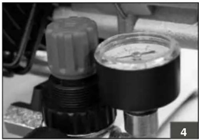
natural_image
Close-up of a pressure regulator dial and adjustment knob (no visible text or symbols)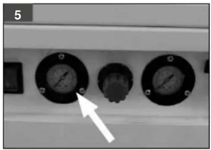
natural_image
Close-up of three circular industrial gauges with a white arrow pointing to one (no visible text or symbols)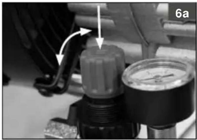
natural_image
Close-up of a mechanical pressure regulator with a valve and gauges, no visible text or symbols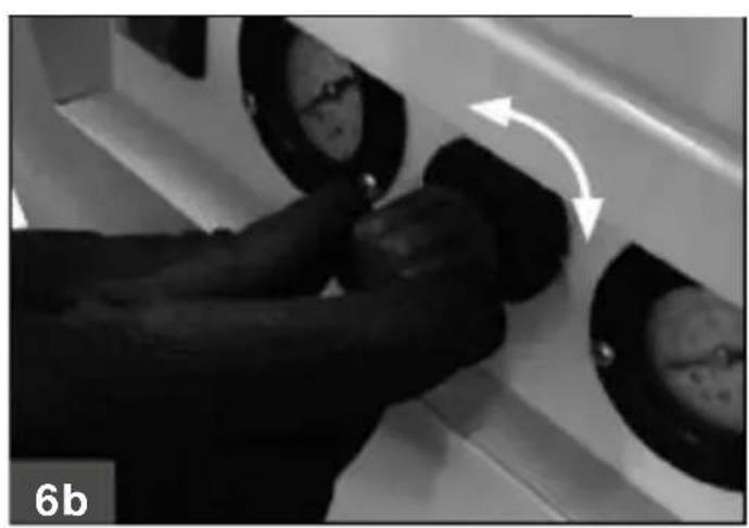
natural_image
Close-up of a person pressing down on a mechanical component with circular components and an arrow indicating motion (no text or symbols)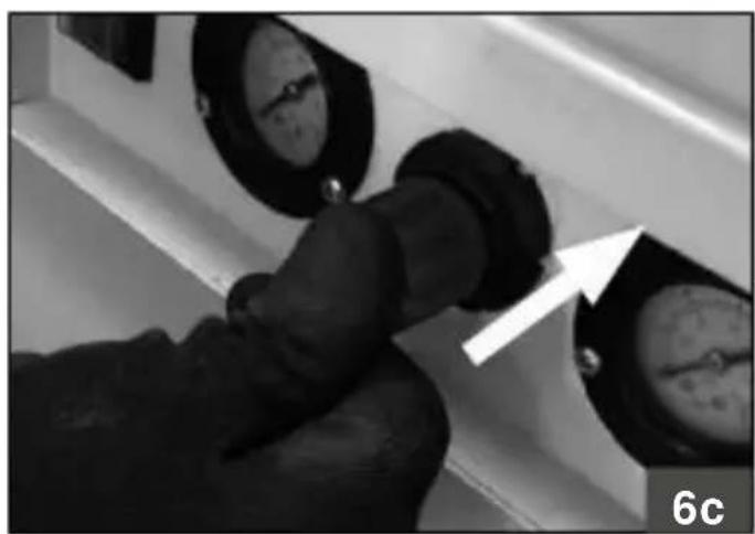
natural_image
Close-up of a hand adjusting a pipe fitting with pressure gauges, no visible text or symbols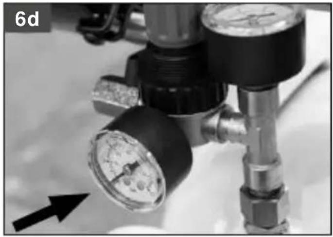
natural_image
Close-up of a pressure regulator with gauges and tubing (no visible text or symbols)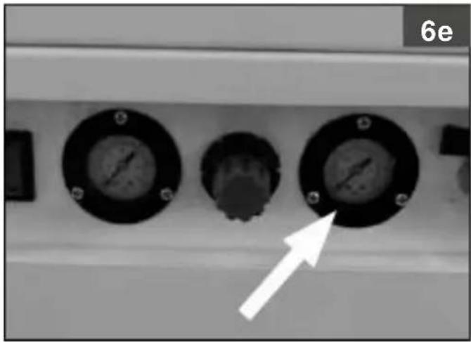
natural_image
Close-up of three circular gauges with a white arrow pointing to one (no text or symbols visible)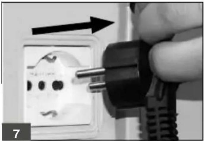
natural_image
Close-up of a hand using a power plug to install an electrical socket (no text or symbols visible)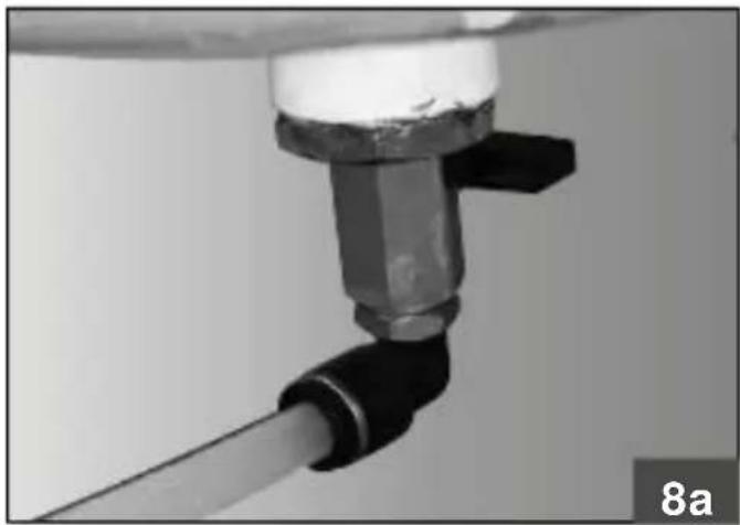
natural_image
Close-up of a mechanical component with a black connector and pipe fitting (no visible text or symbols)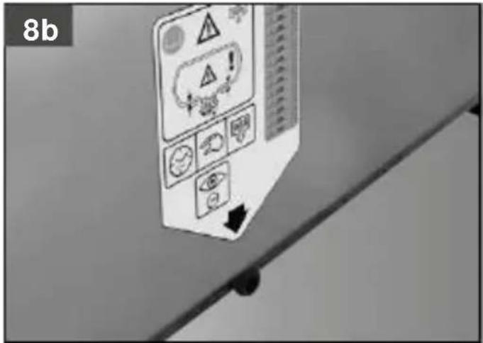
text_image
8b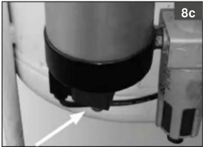
natural_image
Close-up of a mechanical component with a curved arrow pointing to a feature, labeled '8c' in the corner (no readable text or symbols beyond label)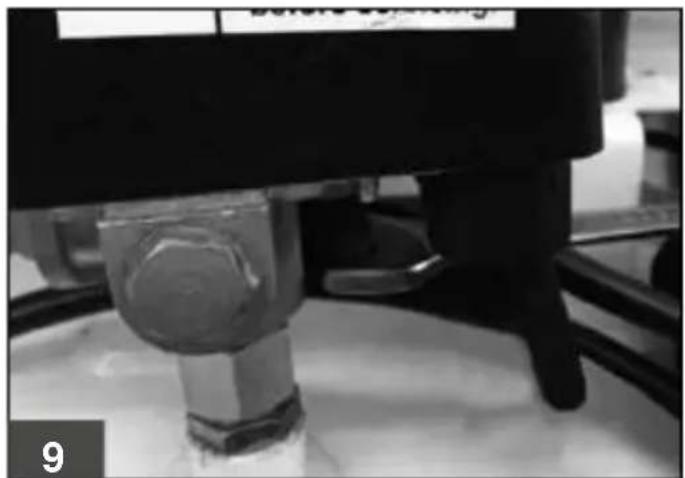
natural_image
Close-up of a mechanical press or valve component with a transparent glass cap and base, no visible text or symbols.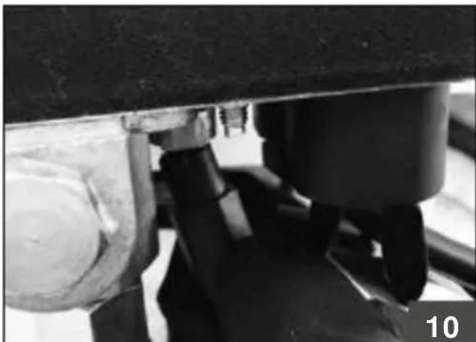
natural_image
Close-up of a mechanical assembly with no visible text or symbols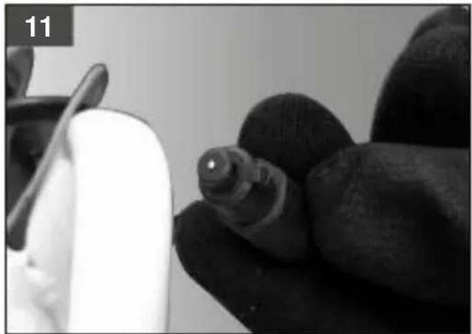
natural_image
Close-up of a gloved hand holding a small object, possibly a tool or device, with no visible text or symbols.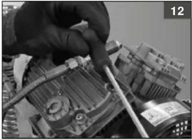
natural_image
Close-up of a hand using a tool to adjust or install a mechanical component (no visible text or symbols)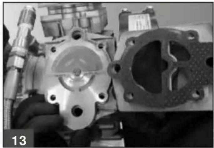
natural_image
Close-up of an engine cylinder head with internal cavities and mounting holes (no visible text or symbols)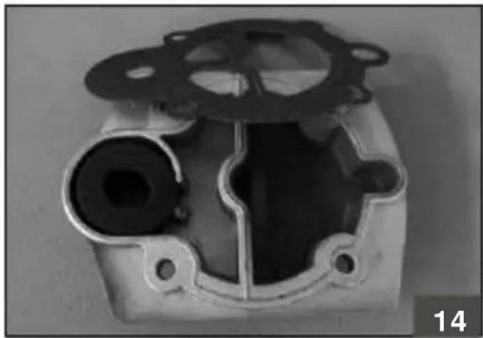
natural_image
Metal mechanical component with internal cavity and mounting flanges (no visible text or symbols)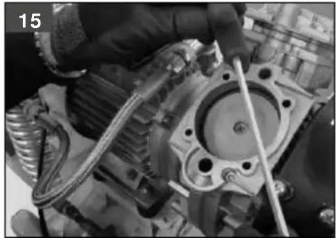
natural_image
Close-up of a hand using a tool to adjust or install an engine cylinder (no visible text or symbols)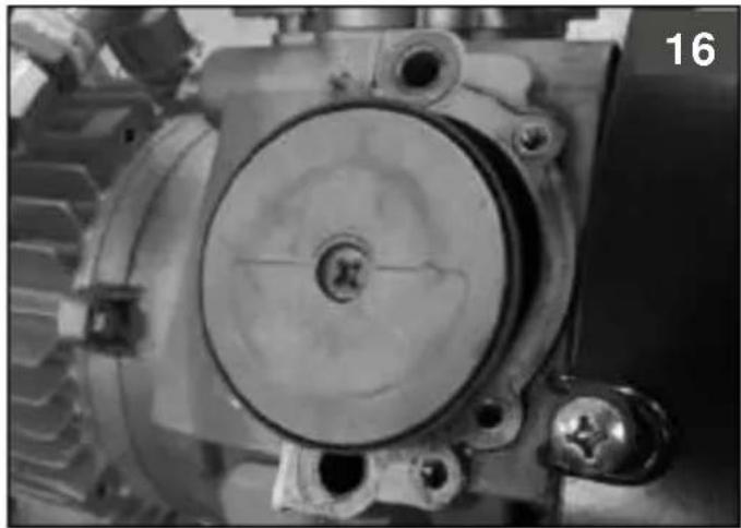
natural_image
Close-up of a mechanical component with gears and mounting holes (no visible text or symbols)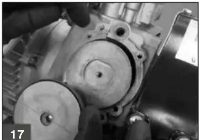
natural_image
Close-up of mechanical components with visible gears and shafts, no text or symbols present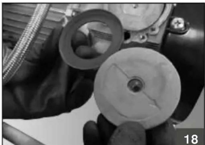
natural_image
Close-up of hands holding a mechanical component with visible gears and a central shaft (no text or symbols)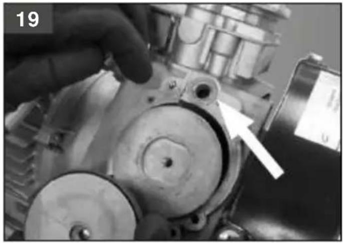
natural_image
Close-up of a mechanical component with a hand adjusting parts, showing no visible text or symbols.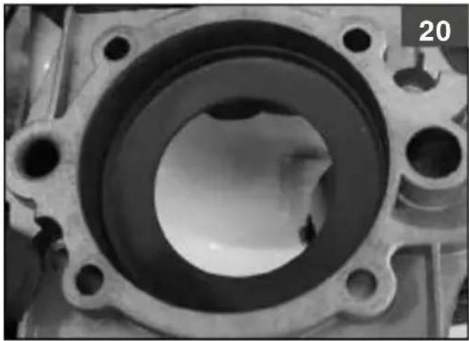
natural_image
Close-up of a mechanical component with concentric rings and mounting holes (no visible text or symbols)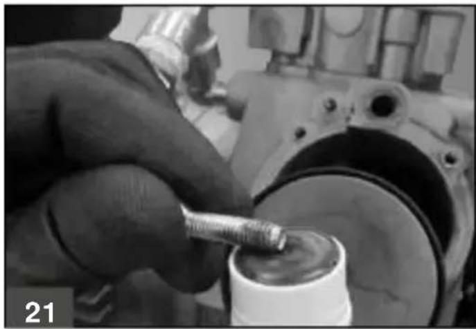
natural_image
Close-up of a hand using a tool to work on a mechanical component, no visible text or symbols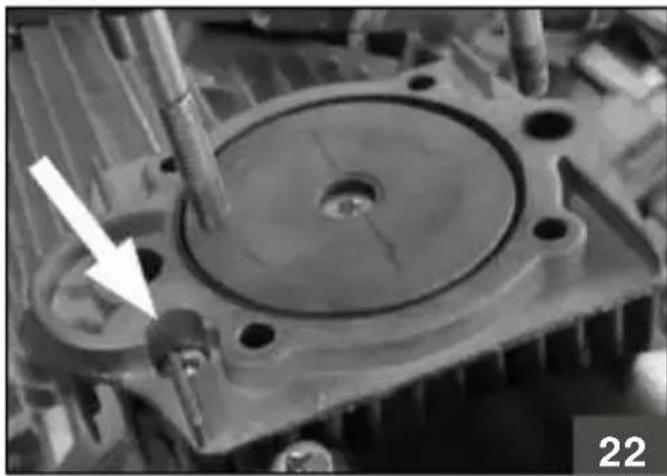
natural_image
Close-up of a mechanical component with a white arrow pointing to a circular feature, no visible text or symbols.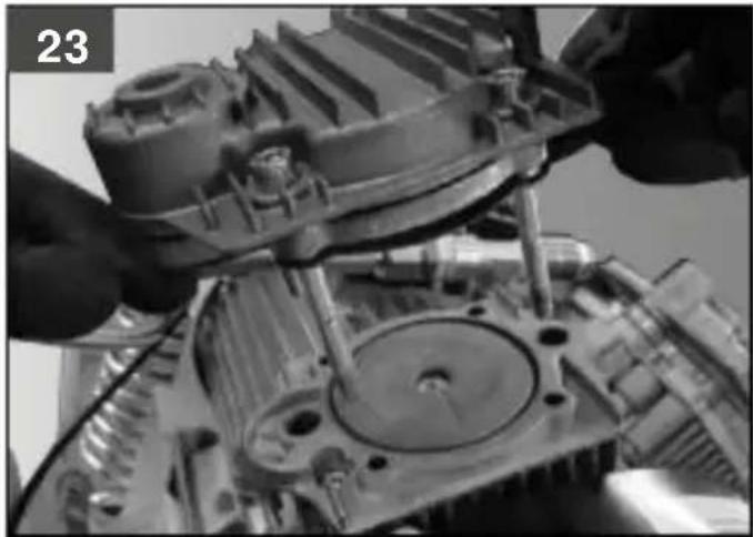
natural_image
Close-up of hands assembling a mechanical component with visible gears and shafts (no text or symbols)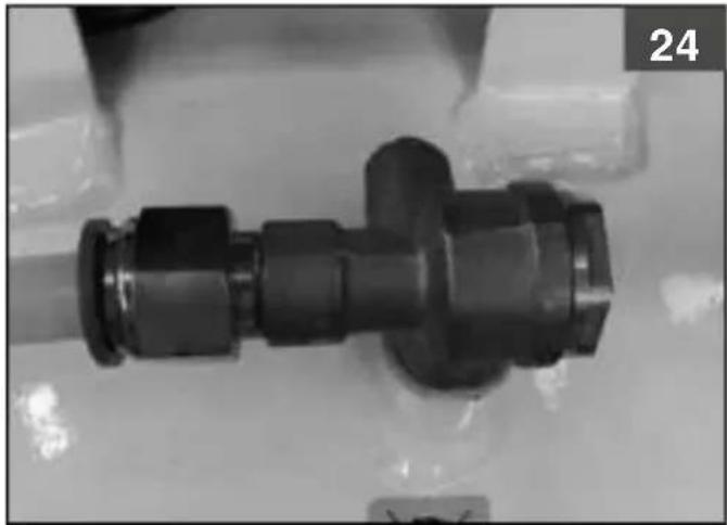
natural_image
Close-up of a black mechanical connector or fitting with flanged ends and a central shaft, placed on a surface (no visible text or symbols)
natural_image
Close-up of a hand holding a metallic ring component, no visible text or symbols | |
| I | Leggerattentamentiemanualed'istruzionprimadell'uso |
| GB | Beforeuse,read the handbookcarefully |
| F | Lire attentivemeletManuelOpérateuravantouteutilisation |
| D | VorlnbetriebnahmGebrauchsanleituagfmerksartesen |
| E | Leeratentamentelmanualdeinstruccionesantesde usarel equipo |
| P | Ler comatençao manuade instruçõesantesdouso |
| NL | Leesvóór gebruikandachtige handleidingloor |
| DK | Læsomhyggeliinstruktionsmanualsørbrug |
| S | Läs bruksanvisningengoggranföre användning |
| FIN | Lue käyttöopahuolellisesännenkäyttöä |
| GR | Διοβάσταροσεκτικόεγχειρίδιοδηγιώνπην στότη χρήση |
| PL | Przedužyciemaležydokladniezapoznašie zinstrukcijamobsługi |
| HR | Prijeupotrebepažljivopročitajteputera upotrebu |
| SLO | Predzagonomskrbnqpreberitenavodilaa uporabo |
| H | Használaelöttigyelmeserolvassal a kézikönyvet |
| CZ | Predzahájenínorácesi pozorněřečtětepříručkwpoužití. |
| SK | Predpouživanímýrobkusi pozorneprečítajteávodna jeho použitie. |
| RUS | Передем,как приступитьработе,внимательнрочитайтінструкцию эксплуатации |
| NO | Les noye bruksanvisningénbruk |
| TR | Kullanımdaöncekullanımkilavuzundikkatlicekuyunuz. |
| RO | Cititicu atentienanualude instructiuninaintele utilizare! |
| BG | Внимателнрочетеръководството експлоатациредупотреба |
| SRB | Pre upotrebpažljivopročitajteputstvaza upotrebu |
| LT | Priešdamiesidarbatidžiaperskaitykitenaudojimradovėli |
| EST | Erne kasutamistugegekasutamisjuhentähelepanelikląbi. |
| LV | Uzmanīgizlasiezmantošanaisstrukcijupirmsproduktāietošanas |
| I | Pericoldiscottature |
| GB | Warninghot surfaces |
| F | Risquedebrûlures |
| D | Verbrennungsgefahr |
| E | Peligrode quemaduras |
| P | Perigode queimaduras |
| NL | Gevaavoor brandwonden |
| DK | Risikdor skoldning |
| S | Riskför brännskador |
| FIN | Palovammavaara |
| GR | Kivõuvoçykaujátuw |
| PL | Uwagagrozipoparzeniem |
| HR | Pozowruće površine |
| SLO | Nevarnostpeklin |
| H | Figyelemégetőfelületek |
| CZ | Nebezpečípálení! |
| SK | Nebezpečenstvopáleniá |
| RUS | Onacnostůxjora |
| NO | Farofor á brenneseg |
| TR | Yanmaehlikesi |
| RO | Pericodearsuri |
| BG | Onacnosot изгаряния |
| SRB | Opasnostd opekotina |
| LT | Nudegimpavojus |
| EST | Süttivusøht |
| LV | Piesargietiesoapdedzināšanās |
| I | Protezioneobligatoridellavista |
| GB | Obligatorye protection |
| F | Proteciodes yeux obligatoire |
| D | Sichtschutobligatorisch |
| E | Protecciónobligatoride la vista |
| P | Proteçáobrigatórios olhos. |
| NL | Beschermingspliktor hetgezicht |
| DK | Obligatorisbeskyttelsesbriller |
| S | Obligatoriskayddglasōgon |
| FIN | Pakollinesilmiersuojaus |
| GR | Утохрөштікпроостаσιάρασης |
| PL | Obowiązkowabezpieczeninizroku |
| HR | Obaveznazaštitza očiju |
| SLO | Obveznazaščitači |
| H | Kötelezőzemvédelem |
| CZ | Povinnáchranazraku |
| SK | Povinnáchranazraku |
| RUS | Обязательнащитарения |
| NO | Obligatoriskeskyttelsev synet |
| TR | Mecburlaraközlerinkorunması |
| RO | Protejareabligatoria vederii |
| BG | Задължителнащитана очите |
| SRB | Obaveznazaštitačiju |
| LT | Privalonapsauginiaikiniai |
| EST | Kohustuslilsilmakaitse |
| LV | Obligātedzesaizsārdzība |
9
 | |
| I | Pericolavviamentautomatico |
| GB | Danger automatic control(closedoop) |
| F | Risque demarrageautomatique |
| D | Gefah durch automatisch amlauf |
| E | Peligrde arranque automático |
| P | Perigarranque automático |
| NL | Gevaavoor automatischtarten |
| DK | Fare automatiskart |
| S | Riskör automatiskart |
| FIN | Automaattisekäynnistymiseraara |
| GR | Kivõuvogutóματηφκίνησης |
| PL | Uwaganiebezpieczeńst automatyczneguruchomienisię |
| HR | Opasnosbog automatskpgkretanja |
| SLO | Nevarnostaradisamodejnegaagona |
| H | Automatikubeindulásveszélye |
| CZ | Nebezpečiautomaticképouštění! |
| SK | Nebezpečenstvaomaticképustenid |
| RUS | Опасноставтоматическогоключения |
| NO | Fare for automatisloppstart |
| TR | Dikkabtomatikcalismäehlikesi |
| RO | Pericofornireautomata |
| BG | Опасноставтоматичнорусканевход |
| SRB | Opasnosbog automatskpgkretanja |
| LT | Automatinisijungimopavojus |
| EST | Ohtlikautomaatilinkäivitus |
| LV | Uzmanībuautomātiskädarbināšanās |
| I | Attenzioncorrentelettrica |
| GB | Dangerousoltage |
| F | Attentionprésencedecourantélectrique |
| D | AchtungelektrischeSpannung |
| E | Atencióncorrienteeléctrica |
| P | Atençãocorrentelectrica |
| NL | Attentie,elektrischstroom |
| DK | Advarselektriskström |
| S | Varning-elektricitet |
| FIN | Huom.vaarallinejännite |
| GR | Прогохімлектрикфезура |
| PL | Uwaga,niebezpieczeństworazeniaprademelektrycznym |
| HR | Pažnja,električniapon |
| SLO | Pozorelektričnapetost |
| H | Figyelem,elektromoáram |
| CZ | Pozor- elektrickéapěti! |
| SK | Pozor- elektrickyrúd! |
| RUS | Опасностудара электрическимоком |
| NO | Forsiktigelektriskström |
| TR | Dikkatelektrikakımı |
| RO | AtențiePericolelectric |
| BG | Вниманиеелектричекиток |
| SRB | Pažnja,električniapon |
| LT | Elektrostamposrizika |
| EST | Ettevaatust elektrivool |
| LV | Esiet uzmanîgielektrîbasplûsma |
| I | Gruppopompante |
| GB | Pumpingunit |
| F | Groupepompant |
| D | Pumpgruppe |
| E | Grupodebombeo |
| P | Unidadeebombeamento |
| NL | Pompgroep |
| DK | Pumpeaggregat |
| S | Pumpenhet |
| FIN | Pumppuryhmä |
| GR | Аvtлнгикóutyкрótημα |
| PL | ZespóPompujacy |
| HR | Pumpnagrupa |
| SLO | Črpalnaenota |
| H | Szivattyégység |
| CZ | Systémvstřikovacíhőerpadla |
| SK | Vstrekovaciaústava |
| RUS | Компрессорнаяголовка |
| NO | PumpéGruppe |
| TR | Pompalamàrubu |
| RO | Grup depompare |
| BG | Изномпващарупа |
| SRB | Pumpnagrupa |
| LT | Pompavamfrenginys |
| EST | Kompressopump |
| LV | Sūknugrupa |
| I | Potenzamotore |
| GB | Power |
| F | Puissancanoteur |
| D | Motorleistung |
| E | Potencianotor |
| P | Potênciao motor |
| NL | Motorvermogen |
| DK | Motorstyrke |
| S | Motorstyrka |
| FIN | Moottorineho |
| GR | Isoxúç kivntnpa |
| PL | Moc silnika |
| HR | Snagamotora |
| SLO | Moč motorja |
| H | Motorteljesítménye |
| CZ | Výkormotoru |
| SK | Výkormotora |
| RUS | Мощностьмотора |
| NO | Effektmotor |
| TR | Motorgüöü |
| RO | Putereamotorului |
| BG | Мощностіа двигателя |
| SRB | Snagamotora |
| LT | Varikligalingumas |
| EST | Mootorivõimsus |
| LV | Motorjäuda |
| I | Capacitāserbatoio |
| GB | Tank capacity |
| F | Contenance réservoir |
| D | Behältergröße |
| E | Capacidaddepósito |
| P | Capacidadeo reservatório |
| NL | Tankcapaciteit |
| DK | Brændstoftankapacitet |
| S | Brānsletankapacitet |
| FIN | Säiliöntilavuus |
| GR | Ikavótnrpečepßouóp |
| PL | Pojemnosžbiornika |
| HR | Kapacitellačneposude |
| SLO | Velikostlačneposode |
| H | A tartálýrtartalma |
| CZ | Objemnádrže |
| SK | Objemnádrže |
| RUS | Объересивера |
| NO | Kapasitemagasin |
| TR | Depokapasitesi |
| RO | Capacitateaezervorului |
| BG | Kanaçitetapezervoara |
| SRB | Kapacitetezervoara |
| LT | Bako talpa |
| EST | Paagimahutavus |
| LV | Rezervuārietilptība |
| I | Aria aspirata |
| GB | Air intake |
| F | Air aspiré |
| D | Eingesauqteuft |
| E | Aire aspirado |
| P | Araspirado |
| NL | Geaspireerdlucht |
| DK | Luftforbrug |
| S | Luftförbruk |
| FIN | Imettyilma |
| GR | Аторророύμενοσέρας |
| PL | Powietrzeasysane |
| HR | Usiszraka |
| SLO | Količinasesanegaraka |
| H | Elszívottevegő |
| CZ | Nasávanýzduch |
| SK | Nasávanýzduch |
| RUS | Производительность |
| NO | Aspireltuft |
| TR | İçineçekilenhava |
| RO | Debiaspirat |
| BG | Всмуканъздух |
| SRB | Usisivanjeazduha |
| LT | İšsiurbtasras |
| EST | Ära imetavõhk |
| LV | lesüktaisgaiss |
 | |
| I | Correnta assorbita |
| GB | Absorbedcurrent |
| F | Courant Absorbé |
| D | Verbrauchte strom |
| E | Corrienta absorbida |
| P | Correnta obsorvida |
| NL | Opgenomenstroom |
| DK | Strømforbrug |
| S | Strömförbrukning |
| FIN | Ottovirta |
| GR | Katavačločkóvýručuč |
| PL | PradPobrany |
| HR | Absorbiranaenergija |
| SLO | Absorbiranělektričnitok |
| H | Elnyeltáram |
| CZ | Spotřebæl. energie |
| SK | Prúdová spotreba |
| RUS | Потребляемый |
| NO | Strøm Absorbert |
| TR | Čekilenenerii |
| RO | Curentabsorbit |
| BG | Консумиранок |
| SRB | Absorbovananenergija |
| LT | Sugertael. srově |
| EST | Kasutatavelekrivool |
| LV | Elektriskā strāva Patēriņš |
| I | Pressionmax. |
| GB | Max. pressure |
| F | Pressiomax. |
| D | maximaldruck. |
| E | Presiónmáx. |
| P | Pressámáxima |
| NL | Max. druk |
| DK | Max. tryk |
| S | Max. tryck |
| FIN | Paineenint. |
| GR | Avúttatmícon |
| PL | Ciśnienimax. |
| HR | Najvećtlak |
| SLO | Maksimalntlak |
| H | Maximalisyomás |
| CZ | Maximalntlak |
| SK | Max. tlak |
| RUS | Mаксимальнодавление |
| NO | Maks.trykk |
| TR | Maksimunfasinç |
| RO | Presiuneanax. |
| BG | Maks.naлягане |
| SRB | Najvećpritisak |
| LT | Maks.slégis |
| EST | Maksimunsurve |
| LV | Maks.Spiediens |
 | |
| I | Giri /min. |
| GB | Revolution'smin. (rpm) |
| F | Tours mn |
| D | U/min |
| E | Revoluciones'min. |
| P | Rotações minutos |
| NL | Toerentallper minuut |
| DK | Omdrejningérmin |
| S | Varv / min |
| FIN | Kierrostámin |
| GR | Строфёг λεπτά |
| PL | Obroty/ min |
| HR | Okretají' min |
| SLO | Vrt./Min |
| H | Fordulatszárhperc |
| CZ | Otáčky/ min |
| SK | Otáčky/ min |
| RUS | Обороты/мин. |
| NO | Omdrejningérmin |
| TR | Devir' dakika |
| RO | Rotatjí' min. |
| BG | Оборотимин |
| SRB | Broj obrtajámin |
| LT | Apsukosmin |
| EST | Pööret/min |
| LV | Apqriezieni/min |
| I | Tensione frequenza |
| GB | Voltagand frequency |
| F | Tensioatfréquence |
| D | Spannungnd Frequenz |
| E | Tensión frecuencia |
| P | Tensäe frequência |
| NL | Spanningen frequentie |
| DK | Spændingg frekvens |
| S | Spänningch frekvens |
| FIN | Jännitejataajuus |
| GR | Tönn korsuyvótna |
| PL | Napięciéczestotliwość |
| HR | Naponi frekvencija |
| SLO | Napetosin frekvenca |
| H | Feszültségsfrekvencia |
| CZ | Napätia frekvence |
| SK | Napätia frekvencia |
| RUS | Напряжениечастота |
| NO | Spenningg frekvens |
| TR | Gerilime frekans |
| RO | Tensiungifrecventă |
| BG | Напрежениечестота |
| SRB | Naponi frekvencija |
| LT | Itampań dażnis |
| EST | Pingejasagedus |
| LV | Spriegumsinfrekvence |
 | |
| I | Quantità di oio |
| GB | Oil amount |
| F | Quantità uile |
| D | Ölmenge |
| E | Cantidadle aceite |
| P | Quantidade deoeo |
| NL | Hoeveelheidie |
| DK | Oliemaengde |
| S | Oliemängd |
| FIN | Öliynmäärä |
| GR | Посотнікідю |
| PL | Ilośoleju |
| HR | Kolicinauja |
| SLO | Količinaola |
| H | Olajmennyiség |
| CZ | Množstvoleje |
| SK | Množstvoleja |
| RUS | количество масла |
| NO | Kvantitebje |
| TR | Yag miktarı |
| RO | Cantitatelei |
| BG | Количество масло |
| SRB | Kolicinauja |
| LT | Alyvoskiekis |
| EST | Öli hulk |
| LV | Ellasdaudzums |
| I | Sezioneavo di alimentazione |
| GB | Powercablecrosssection |
| F | Sectioncabled'alimentation |
| D | Speisekabelschnitt |
| E | Secciódel cablede alimentación |
| P | Bitoladocabo dealimentação |
| NL | Doorsnedroedingskabel |
| DK | Forsyningskabel |
| S | Sektionför kraftkabel |
| FIN | Syöttökaapejnoikkipinta-ala |
| GR | Διατομήκαλωδιούροφοδοσίας |
| PL | Przekrökablązasilającego |
| HR | Sekcijanapojnogabla |
| SLO | SklopNapajalniabel |
| H | Tápvezetášć metszet |
| CZ | Průměnapájecíhkabelu |
| SK | Priereznapájaciehkábla |
| RUS | сеченитокоподводящекабеля |
| NO | Avdelingratekabel |
| TR | Beslemkablosukesiti |
| RO | Sectiuneablude alimentare |
| BG | Секцияхранващкабел |
| SRB | Presekapojnogkabla |
| LT | Maitinimälabeliskyrius |
| EST | Toitekaabitlõige |
| LV | BarošanaskabelaSekcija |
flowchart
graph TD
    A["Warning"] --> B{Warning?}
    B --> C["Warning icon: exclamation mark"]
    B --> D{Warning?}
    D --> E["Warning icon: hand gesture"]
    D --> F{Warning?}
    F --> G["Warning icon: eye symbol"]
    H["1/20"] --> I["☐"]
    J["2/20"] --> K["☐"]
    L["3/20"] --> M["☐"]
    N["4/20"] --> O["☐"]
    P["5/20"] --> Q["☐"]
    R["6/20"] --> S["☐"]
    T["7/20"] --> U["☐"]
    V["8/20"] --> W["☐"]
    X["9/20"] --> Y["☐"]
    Z["10/20"] --> AA["☐"]
    AB["11/20"] --> AC["☐"]
    AD["12/20"] --> AE["☐"]
    AF["13/20"] --> AG["☐"]
    AH["14/20"] --> AI["☐"]
    AJ["15/20"] --> AK["☐"]
    AL["16/20"] --> AM["☐"]
    AN["17/20"] --> AO["☐"]
    AP["18/20"] --> AQ["☐"]
    AR["19/20"] --> AS["☐"]
    AT["20/20"] --> AU["☐"]
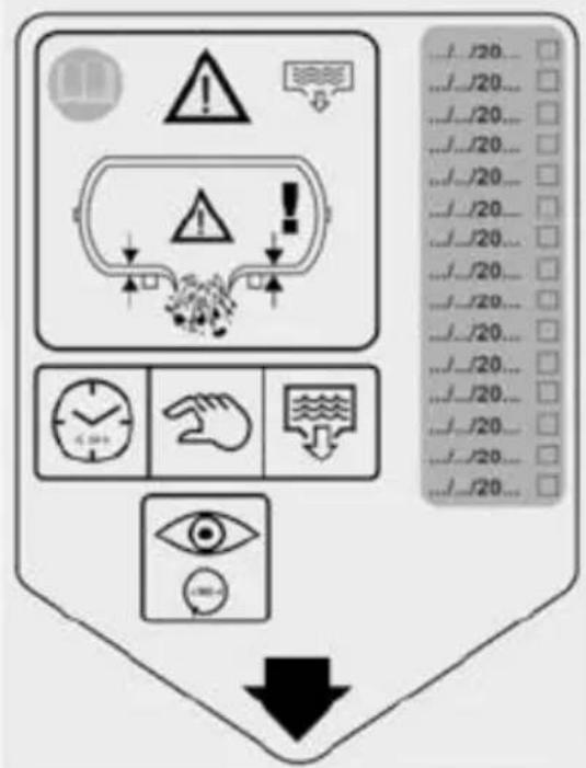
| I | Etichettaspurgo spurgaril serbatoiogni giorno far controllaranualmentespessoredellaparetedel serbatoiola un organismnotificato, annotandsull'etichetta data dell'intervento. |
| GB | Drainlabel-drainout the tank daily-annuallyhave the thicknessofthe tank wallscheckedbya competenbodyrecordingte date of the servicetask on thelabel. |
| F | Étiquettade purge-purgeleréservoiquotidiennementfairecontrôleannuellementépaisseude la paroiduréservoipar un organismcompetenten inscrivanta date d'interventisior l'étiquette. |
| D | Entlüftungsetiketten Druckluftbehälteäglichentlüftenjährlichdie Wandstärkdes Behältenon einerzuständigeStelleprüferlassenund das Datum der Überprüfunem Etiketvermerken. |
| E | Etiquetade purga-purgaredepósitdotodoslos días-anualmentencargara un organismcompetentan controldelgrosorde laparedapuntanden la etiquetta fechade laactuación. |
| P | Etiquetade purga-esvaziereservatória cada da -deve ser verificadanualmente espessurala parededo reservatóripor parte de umorganismo competentobservandnætiquetaadatada intervencão. |
| NL | Etikebntluchtingontluchhetreservoirdagelijks laatjaarlijksdedikte van de wand vanhetreservoicontrolerador een bevoegdinstantien noteer de datumran de werkzaamheqhetetiket. |
| DK | Udlobetstiket-tomtankenhver dag-ladtankensvægtykkelskontrolleren gangomåret afet kompetentrganog anførkontroldatoepå etiketten. |
| S | Tömningsetikettöm tankenvarjedag-lätärligerkontrolleratankväggarnajsckleavett kompetentorgannoteradatumepå etiketterför inspektionen. |
| FIN | Tyhjennykseëtiketti tyhjennäsäiliöpäivittäintarkastutsäiliönseinänpaksuusvuosittaipätevälläaitoksellaçoimenpiteesuorituspäiväulee merkitäetikettiin. |
| GR | Etikétattoostrávyισηγα εκτελείτικοθημερινήποστράγγισηφεξαμενήγα αναθέτετετησίωγονέλεγχοιου πάχουφων τοιχωμάτωης δεξαμενής σε ορυόδιφορεόκα νακατανρόφεννημερουνίσου σέρβικτην ετικέτα. |
| PL | Zawieszkapustu-oprózniąbiornikcodziennie corokunaležyzleciósprawdzenigrubościścianzbiornikaorganowo odpowiednickompetencjach, zapisendaty czynnosśserwisowehazawieszce. |
| HR | Oznakaa odvod-spremnilpraznitesvakodnevne svakegodineprovjeravajdebljinstijenkespremnikapradležnomtijelukojeće na oznachaznačiti datumposliednieservisaspremnika. |
| SLO | Oznakaa praznjenje-rezenvoaizpraznitesak dan-ustreznitrokovnörgammora vsakleto izvestpregledz. meritevdebelinstenerezervoarja na nalepkovarestidatumservisnegregleda. |
| H | Leeresztőcímke-napontaresszelea tartályt éventeellenőriztesse tartályfalvastagságát illetékehatóságga a címkértüntessefela szerviz dátumát. |
| CZ | Štítekodvzušněnbdvzdušňujteádobukażdyjen - každýrok nechtezkontrolovatloušt'katěnyvzdušníkpříslušnýmorgánema naštítek poznamenejdatumtélokontroly. |
| SK | Štítokistenie každodennéistihádrž- každoročnecha'tskontrolovatrúbkustiennádržekvalifikovandumouktorávyznačina štítkudátumúkonu. |
| RUS | Этикеткредувкиежедневносуществлятпродувкубака ежегодніроверятьолщинутенкибака компетентньдрганомрегистрирува этикетквратупроверки. |
| NO | Etikettforavtappingtappeavtankenhverdag -tykkelsenil veggeni tankemä årligkontrolleresav et kvalifiseorganog datoenforkontrollskal merkes av påetiketten. |
| TR | Boşaltmetiketi-depoyugünlükyıllikolaralboşaltınızdepo cidarlarınınkalınlığinyetkilbir kuruma kontroéttirinizebu servisisleminirtarihininetikete kaydediniz. |
| RO | Etichetärivindevacuareaagolitizilnicrezervoruul verificațanualgrosimeperetjilo rezervorulula autoritatecompetentänregistrândata verificăripe etichetä. |
| BG | Табелкаа продухванепродухвана резервоарвсекијен -трябварасе проверявъеднъходишнєдебелината стенатаа резервоара компетентеорганкato на табелкатве отбелязвидатаналироверката. |
| SRB | Oznakaa odvod-rezenvoapraznitesvakodnevne svakegodineproveravajtelebljinstenkrezervoarapri nadležnotalu kojeće na oznachaznačiti datumposlednieservisaezervoara. |
| LT | Išleidimetiketė kiekvienądienąsleiskitekondensafą rezervuarekartametuoseatsakingastaigapagabetiketėjepažymėtąta turi patikrintbako sienelėstori. |
| EST | Äravoolsilt-laskepaakiga päev tühjaks laskord aastaspädevaalsutusekontrollidapaagiseinadepaksustmärkidesildilehooldustõtuupäeva. |
| LV | Gaisazlaisanasetikete katrudienuizlaidigaisuno tvertnes reizigadāpärbaudietvertnesieninübiezumkompetentajästitűcijānorādotuzetiketes päärbaudedatumu. |
Keep this instruction manual for future reference
For models with dryer, please refer to the relative manual
1 PRECAUTIONS FOR USE

WHAT TODO
What to do
- The compressormust be used in a suitable environment (well ventilated, at an ambient temperature between +5^ and +40^ ) where is no dust, acids, vapours or explosiveor flammable gases.
• Always keep the compressor at a minimum safe distance of 4 metres from the work zone. - Discolouration of the plastic protection on the compressor during the painting process indicates that the compressor is too close.
- Put the plug of the power cable in a socket of a suitable type, voltage and frequency in compliance with the legislation in force.
- Use power cable extensions no more than 5 metres in length and with a cross-sectional area of 2.5 ~mm^2 .
- It is not advisable to use extensions of any other length and cross-sectional area, or adaptors and extension sockets.
• Always turn off the compressor at the pressure switch or control panel. - The compressor in use must be installed on a flat and stable surface.

WHAT NOT TODO
- Never aim the jet of air towards people, animals or yourself (wear protective glasses to protect your eyes against foreign bodies lifted by the jet).
- Never aim the jet of liquid sprayed by tools connected to the compressor towards the same compressor.
- Never use the device when barefoot or with wet hands and feet.
- Never pull the power cable to take the plug out of the socket or to move the compressor.
- Never leave the device exposed to the elements.
- Never move the compressor when the tank is pressurised.
- Never carry out welding or machining on the tank. In the case of defects or corrosion, replace the tank in its entirety.
- Never allow inexperienced people to use the compressor. Keep children and animals away from the work area.
- Do not put flammable objects or objects made of nylon and fabric near and/or on the compressor
- Never clean the machine with flammable liquids or solvents. Make sure to take the plug out of the socket and use only a damp cloth.
• The compressor must be used only for the purpose of compressing air. Do not use the machine with any other type of gas. - The compressed air produced by this machine is suitable for use in the pharmaceuticals, food or hospital sector only when duly treated and must not be used to fill dive tanks.

IMPORTANTNOTES
- This compressor is designed to be run intermittently (for example, S3-50 means 5 minutes' operation and a 5-minute pause) to avoid excessive overheating of the electric motor. The thermal protection of the motor trips, automatically cutting out the power when the temperature is too high. The motor then restarts again automatically when normal operating conditions are restored.
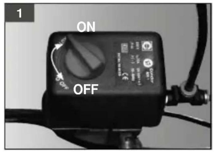
- To facilitate restarting of the machine in the case of forcedrestarting (e.g. after a blackout), follow the procedure above and press the button on the pressure switch to turn itoff and then on again (fig. 1-2).
- Versions without a dryer have a pressure switch with a delayed action air escape valve that facilitates starting of the motor, and it is normal for this valve to release a puff of air for a few seconds when the tank is empty.
- All the compressors have a safety valve that trips if the pressure switch acts erratically, in order to protect the machine.
- It is essential to stop the outgoing flow of air before assembling a tool.
- The use of compressed air for the purposes intended by the manufacturer (supply for dental equipment, inflation, pneumatic tools, painting, washing with water-based detergents) requires familiarity, and compliance, with the standards that apply in each case.
2 START-UPAND USE
- Check that the electrical system is compatible with the data on the nameplate of the compressor; voltage variation of +/- 10% in relation to the nominal value is permitted.
- Put the plug of the power cable in a suitable socket (fig. 3) after making sure that the button of the pressure switch on the compressor is turned to "O" (OFF).
- The compressor is now ready for use.
- Press the button on the pressure switch (fig.1-2) to start the compressor which then pumps air into the tank via the delivery pipe.
- When the upper calibration value (set by the manufacturer during the acceptance test) is reached, the compressor stops and discharges excess air in the head and delivery pipe via a small valve located under the pressure switch or, for versions with dryer, via the solenoid valve.
The release of all pressure in the head facilitates subsequent restarting. The compressor uses air to restart automatically when the lower calibration value is reached (there is a difference of 2 bar between the upper and lower calibration values) - A pressure gauge is provided fig. 4-5) for checking the pressure in the tank.
- The compressor continues to run automatically until the button on the pressure switch is pressed.
- After turning off the compressor, wait a minimum of 10 seconds before restarting it again.
- All the compressors come with a pressure reducer. Adjust the knob with the valve open (pull and turn it clockwise to increase the pressure and anti-clockwise to decrease it, fig. 6a-6c) to set the air pressure and thereby optimise use of the pneumatic tools. After setting the required value, push the knob to lock it.
- There is a pressure gauge (fig.6d-6e) for checking the set value.
- Check that the consumption of air and the maximum operating pressure of the pneumatic tool to be used are compatible with the pressure set on the pressure regulator and the amount of air supplied by the compressor.
- After use, stop and unplug the machine and empty the tank (fig. 7).
3
AIR TANK
- Corrosion must be avoided: depending on the conditions of use, condensation can accumulate in the tank and must be drained out on adaily basis. This can be done manually by opening the escape valve (fig. 8a,8b). The dryer, when applicable, is emptied automatically (fig. 8c).
Check the correct working order of the automatic valve on a weekly basis. - Thethickness of the wall of the air tank must be checked by a competent body on an annual basis as corrosion on the inside can cause thinning of the steel wall and the risk of explosion. Observe any local regulations in force that apply. The air tank must not be used when the thickness of
the wall reaches the minimum value indicated in the tank certification (part of the documentation provided with the unit).
- The life-span of the air tank depends mainly on the operating environment. Avoid installing the compressor in a dirty and corrosive environment as this can greatly reduce the life-span of the tank.
- Do not anchor the tank or its components directly onto the ground or onto rigid structures. Assemble anti-vibration pads on the tank to prevent faults due to excessive stress caused by vibration of the tank during use.
- Use the tank observing the temperature and pressure limits on the data plate and in the test report.
- Do not carry out welding, drilling or machining to modify the machine in any way.
MAINTENANCE
4
- BEFORE CARRYING OUT ANY MAINTENANCE, UNPLUG THE MACHINE, EMPTY THE ENTIRE TANK AND ALLOW THE MACHINE TO COOL DOWN (FIG. 7, 8a, 8b, 8c).
- Check that all the screws, and those on the head of the unit in particular, are properly fastened (torque 10Nm = 1.02Kgm ).
This check must be carried out before starting the compressor for the first time and after the first hour of operation.
TABLE1 - MAINTENANCE SCHEDULE NORMAL WORK ENVIRONMENT
| OPERATION | EVERY100 HOURS | EVERY1000HOURS | EVERY2000HOURS |
| Fasteningofthe headtle-rods | This checkmust be carriedout before starting the compressofothe firsttime and after the firsthour of operation. | ||
| Cleaningthefilterelement | ● | ||
| Replacingthe small valve of the pressureswitch(when applicable) | ● | ||
| Replacinghe filterelement | ● | ||
| Checkingandcleaninghe valveplate | ● | ||
| Replacinghe cylinderegment | ● | ||
| Replacinghe checkvalve | ● | ||
| Replacinghe valveplate | ● | ||
| Replacinghethilters ofthe drye(whenapplicable) | Referto therelativemanual | ||
| Drainingcondensation the tank | 24h ----> 24h ---->24 h---->. | ||
TABLE2- MAINTENANCE SCHEDULE DAMP/DUSTWORK ENVIRONMENT
| OPERATION | EVERY50HOURS | EVERY 500HOURS | EVERY1000HOURS |
| Fasteningofthe headtie-rods | This checkmust be carriedout beforestartinghe compressofothe firsttime and after the firsthour of operation. | ||
| Cleaningthefilterelement | ● | ||
| Replacinghesmall valveof the pressureswitch(when applicable) | ● | ||
| Replacinghe filteelement | ● | ||
| Checkingandcleaninghe valveplate | ● | ||
| Replacinghe cylinderegment | ● | ||
| Replacinghe checkvalve | ● | ||
| Replacinghe valveplate | ● | ||
| Replacinghefiltersofthe drye(whenapplicable) | Referto therelativemanual | ||
| Drainingcondensation the tank | 24h ----> 24h ---->24 h---->.. | ||
- Loosen the small valve on the pressure switch (Fig. 9)
REPLACING THE SMALL VALUE OF THE PRESSURE SWITCH (WHEN APPLICABLE) - Assemble the new small valve and fasten it in place.
CLEANING AND/ORREPLACING THEFILTER ELEMENT
- Undo the screws in the head using the Allen key (fig.12)
- Remove the cylinder head (fig.13)
- Check the filter element and replace it if necessary (fig. 14)
- Reassemble the head and tighten the screws (fig.12)
CHECKING, CLEANING AND REPLACING THE VALVE PLATE
- Undo the screws in the head using the 5 mm Allen key (M6 socket screw) (fig. 12)
- Remove the cylinder head (fig.13)
- Clean the valve plate and replace it if necessary (fig.10)
- Reassemble the head and tighten the screws (fig.12)
REPLACINGTHE CYLINDERSEGMENT AND GASKETS
- Undo the screws in the head using the Allen key (fig.12)
- Remove the cylinder head and the valve plate (fig. 13)
- Replace the head gasket (fig. 14)
-
Unfasten the cylinder with the same Allen key, removing the two screws connecting the cylinder to the guard (fig. 15)
-
Unfasten the central screw of the piston (fig. 16)
- Remove the piston plate (fig. 17)
- Remove the piston segment (fig. 18)
- Replace the O-ring between the guard and the cylinder (fig. 19)
- Assemble the new segment behind the cylinder liner (fig. 20)
- Before putting the screw back in place, apply some threadlocker (LOCTITE 248) (fig. 21)
- Put the screw back in the piston.

MAKE SURE TO ASSEMBLE THE VALVEPLATECORRECTLY!
- Fasten the two screws in the cylinder (fig. 22)
- Put the head on the plate and fasten the 4 screws on the cylinder (fig. 23)
REPLACING THE CHECK VALVE
- Disassemble the valve, removing the Rilsan tube from the same valve (fig. 24)
- Undo and remove the valve.
- Replace the valve and screw it in place.
- Fasten the Rilsan tube.
- Corrosion must be avoided: depending on the conditions of use, condensation can accumulate in the tank and must be drained out on a daily basis. This can be done manually by opening the escape valve (fig.8a, 8b). The dryer, when applicable, is emptied automatically (fig. 8c).
The condensation MUST BE DISPOSED OF in an environmentally friendly manner and according to the laws in force.
The compressor must be disposed of inasuitable manner according to the local regulations.
5 TROUBLESHOOTING AND PERMITTED ACTIONS
| FAULT | CAUSE | ACTION |
| Air leaks out of the valve of the pressure switch when the compressor is at standstill. | The check valve is not working properly because it is worn or there is dirt on the seal. | Unfasten the hexagonal head of the check valve, clean the seat and the special rubber disc (replace it if worn). Reassemble and fasten it with care (fig. 24-25). |
| Decrease in efficiency. Frequent starting. Low pressure values. | Overworking. Test the fittings and/or tubing for leaking. Possible clogging of the suction filter. | Replace the gaskets of the fittings. |
| The compressor stops and restarts by itself after a few minutes. | Tripping of the thermal protection due to overheating of the motor. | Clean the air passages in the conveyor. Ventilate the room. Have the voltage checked. |
| The compressor stops after a few attempts at starting. | Tripping of the thermal protection due to overheating of the motor (or unplugging during operation, or low voltage supply). | Turn on the power switch. Ventilate the room. Wait a few minutes and restart the machine. Remove any extensions of the power cable. |
| The compressor does not stop and the safety valve is tripped. | Irregular operation of the compressor or failure of the pressure switch. | Unplug the machine and contact the assistance centre. |
CONTROLE, REINIGING EN VERVANGING KLEPPENPLAAT

ZAMENJAVENEPOVRATNEGAVENTILA
flowchart
graph TD
    A["Warning"] --> B{Warning?}
    B --> C["Warning icon: exclamation mark"]
    B --> D{Warning?}
    D --> E["Warning icon: hand gesture"]
    D --> F{Warning?}
    F --> G["Warning icon: hand gesture with checkmark"]
    H["Hand icon"] --> I["Warning icon: hand gesture with checkmark"]
    H --> J{Warning?}
    J --> K["Warning icon: hand gesture with checkmark"]
    L["Warning icon"] --> M["Warning icon: hand gesture with checkmark"]
    L --> N{Warning?}
    N --> O["Warning icon: hand gesture with checkmark"]
    P["Warning icon"] --> Q["Warning icon: hand gesture with checkmark"]
    P --> R{Warning?}
    R --> S["Warning icon: hand gesture with checkmark"]
    T["Warning icon"] --> U["Warning icon: hand gesture with checkmark"]
    T --> V{Warning?}
    V --> W["Warning icon: hand gesture with checkmark"]
    X["Warning icon"] --> Y["Warning icon: hand gesture with checkmark"]
    X --> Z{Warning?}
    Z --> AA["Warning icon: hand gesture with checkmark"]
In order to draw your attention to important issues both for the safety as well as the smooth operation of the dryer, a warning

symbolhas been used in this manual. This symbol is placed next to each of the topics that every operator must be familiar with
1.02 PRECAUTIONS
The adsorption dryer is constructed in a workmanlike manner and in accordance with the guidelines of safety standards. The manufacturer further states that the DRYER has been subjected to quality tests under pressure, certifying the conformity of the product.
Before using the DRYERplease readcarefully the followinginformation:

- Carefully read the instructions for the proper functioning of the product.
- Do not allow the air escaping from the compressor to be directed at people or animals..
- Do not operate the machine in a humid place or with poor air exchange.
- Verify that the compressor is located in a stable place.
- The maximum pressure of the compressor is clearly indicated on it.
- When using the compressor, place it in a cool place away from heat sources.
- The compressor can reach high temperatures during operation.
- Do not let children handle the device even when turned off.
- Do not use/compress gas other than air or with oxygen concentrations greater than 21%.
1.03 PRESENTATION AND DESCRIPTION
DRYER 400, is made to dry the air before it is stored inside the tank. This chemical-physical process of heterogenous adsorption, has the task of removing moisture and dew that is formed by compressing air,
resulting in dry air ready for every type of use.
Furthermore, the DRYER 400 is equipped with an external coil for cooling the compressed air; thereby further improving its quality.
DRYER 400 automatically regenerates the dessicant material, purging the residual humidity through a solenoid valve located in the part below the filter cartridge. The air initially passes through the cooling coil, connected to a separator which removes the largest part of moisture. After this first step, the air is forced through the filter cartridge, which eliminates any residual humidity still present, and then finally, moves into a small tank before being stored in the tank of the compressor. At the time of shutdown, after reaching the maximum pressure, dry air in the small tank is flowed slowly and in a contrary manner into the filter cartridge, cleaning the desiccant material from impurities, and at the same time regenerating it.
When all the pressure is released, the last discharge of the first separator also opens, thus draining the system completely.
Your DRYER 400 does not require lubrication or maintenance, and need not be switched on or off, as it comes into operation only when you turn on the compressor.
In case of improper use of the dryer, no responsibility can be attributed to the manufacturer.
Disposal of condensation and dessicant material must be in compliance with the norms and regulations in the country of

installation
1.04 COMPONENTS:
The DRYER is composed of:
- Cooling coil inlet air
- First stage of moisture separation
- Tank with absorbent cartridge
- Non-return valve dry air
- Storage tank for regeneration of the desiccant material
- Automatic condensate drain solenoid valve
1.05 TECHNICALDETAILSDRYER 400
| TECHNICAL DATA LABEL | ||
| DESCRIPTION | UNIT | DRYER00 |
| Regeneration | Processwithoutheat | |
| Application | Air | |
| Nominalcapacity | L/min | 400 |
| Workingpressure | Bar | 8(Max 10) |
| Regen.airconsum. | 0 | |
| Maxtemp.air in | °C | 45 |
| TECHNICAL DATA LABEL | ||
| DESCRIPTION | UNIT | DRYER00 |
| Workingtemp. | °C | -5+45 |
| Fittingin/out | 3/8" - 3/8" | |
| Powersupply | Volt/ Hz | 220/50- 60OR 110/50 |
| Powercons. | Watt | 17 |
| Silicalgecharge | Kg | 1,15 |
| Electricaprotection | IP55 | |
| Totalweight | Kg | 7 |
2 SAFETYREGULATIONS
SAFETY REGULATIONS FOR THE OPERATOR AND 2.01 FOR THE PROPER USE OF DRYER400

The operator of DRYER 400 must have technical knowledge on the relevant safety regulations and be familiar with the operation of the machine perfectly. In the case of delegation of work, the operator must inform the next operator of all of the operations required for the proper use of the machine
The compressor draws air from the surrounding environment (the operator must make sure it is devoid of fumes and / or harmful gases) and passing through a suction filter begins the cycle of compression/filtering up to the tank. Moreover, it is necessary to install an 8-bar safety valve with a flow rate of not less than 400 l/min on the system under pressure after the DRYER.
2.02 SAFETYESSENTIALS

Before using the DRYER 400 please read carefully the following information
- Intake air should not be stale or contaminated, the compressor should not be placed in areas where there is dust, danger of explosion, corrosion or fire.
- Make sure that at the time of service or when you want to replace spare parts on the compressor it is not pressurized and the power plug is disconnected from the power line.
- Replace filter air cleaning parts only with original products.
- When the compressor/dryer is not in use, turn off the power. Never tug on the cable but rather pull the plug to disconnect it from the outlet. Make sure that the cable does not pass over sharp edges or bend at a sharp angle (in this case use an extension).
- Periodically check the general conditions, especially near the joints, and if small defects are present proceed to the replacement of defective parts.
- Periodically check connections for leaks.
- Repair and replace any damaged part only with original spare parts.
- Do not modify the machine except with express written authorization from the manufacturer.
- When starting the machine, make sure people are not in contact with it.
- The operator's and maintenance manual must be available at all times. Put it in an easily accessible place near the machine and protect it from damage.
- All maintenance and repair tasks on the machine, must be performed by qualified personnel.
- Never exceed the maximum working pressure of 10 bar.
3 WARRANTYAND SERVICE
3.01 WARRANTYOF DRYER400
The manufacturer warrants the DRYER 400 for a period of twenty four months from the date indicated on the label on the DRYER.
During the time of production and testing a label is put on the machine showing that it is in conformity with the standards of the European Union showing the CE marking. The warranty is voided if this label is by any reason removed or altered in any way.
For the warranty to be valid, it is necessary that the has complied with the provisions of the contract and that the DRYER
400 has been used as specified and has not been altered or modified without the agreement and confirmation of the manufacturer.
The warranty is not applicable when:
- The machine has not been used properly (as indicated in this manual)
- Non-guaranteed consumable materials and materials of periodic maintenance are used, particularly if used improperly.
- Non original spare parts and replacements are used.
- Gases other than air are used
3.02 SERVICE OF DRYER400
To order spare parts please contact or visit our dealers. In case of difficulty in finding a spare part, contact directly NARDI COMPRESSORI. We are available for any queries or further information and we will put you in contact with skillful technical staff to help you. If you need service or assistance, please contact out dealers in your area.
4 INSTALLATION
4.01 INSTALLATION

In orderto have a goodair quality, it is very important to place the DRYER 400 in a cool and dry place, protected from the elements. The minimum and maximum operating temperature can be found on the table with the technical details, in section 1.05 above. We do not recommend placement in an outdoor environment.
4.02 PLACEMENTON THE COMPRESSOR
The DRYER 400 can be used ONLY with compressors OIL-FREE.
4.03 ELECTRICLINE CONNECTION
Make sure the ground is properly connected to the plug and the electrical system and check that the voltage is correct.
5 MAINTENANCE
The DRYER 400 does not require special maintenance. Check weekly to see if there is moisture in the intermediate separator. If so, contact a technician. Every two years replace the desiccant in the cartridge.
5.02 TROUBLESHOOTINGTABLE
| PROBLEM | CAUSE | POSSIBLESOLUTION |
| TheDRYER400s not working | Electriccurrentmissing | Checkelectridine |
| Badfuse | Replace bad fuse | |
| Electriccurrenttoolow | Checkcompressor | |
| Compressorfailure | ||
| Outgoingair damp | Air intake too high | Check thepumping unit |
| Hightemperature at air intake | Checkroom temperature | |
| Flowcontrol valve defective | Calibratflowregulator or replace | |
| Desiccant material exhausted or saturated | Replacedryercartridge | |
| Solenoid valve defective | Replacesolenoid valve | |
| Lossof pressure on theregeneration tank | Checkconnections | |
| Non-return valve defective | Replace non-return valve | |
| No condensate drain | Problem with thesolenoid valve | Replacesolenoid valve |
| Drainsilence clogged | Cleanthedrain | |
| Flowregulator defective | Calibratflowregulator | |
| Flowregulator not calibrated | Calibratflowregulator |
INFORMATIONDE BASE
1
1.01 EXPLICATIONDU SYMBOLE