60090 TECH - Compressor Aerotec - Free user manual and instructions
Find the device manual for free 60090 TECH Aerotec in PDF.
User questions about 60090 TECH Aerotec
0 question about this device. Answer the ones you know or ask your own.
Ask a new question about this device
Download the instructions for your Compressor in PDF format for free! Find your manual 60090 TECH - Aerotec and take your electronic device back in hand. On this page are published all the documents necessary for the use of your device. 60090 TECH by Aerotec.
USER MANUAL 60090 TECH Aerotec
Instructions for use manual
Manuel utiliseur
Betriebsanleitung
Anomalia Causa Intervention
Before using the compressor, always read the instructions handbook and consult it if you have any doubts regarding compressor functioning.

Important:
Safety goggles MUST be worn when using the compressor.

Warning:
Parts of the compressor may become very hot.

Warning:
The compressor operates according to an automatic on/off cycle and may therefore restart in the case of a blackout and subsequent power-up.

Warning:
Always use sockets with a ground connection to avoid the risk of electric shock.
PRECAUTIONS
THINGS NOT TO DO
THINGS TO DO
Never direct the jet of air towards persons, animals or your body. (Always wear safety goggles to protect your eyes against flying objects that may be lifted by the jet of air).
Never direct the jet of liquids sprayed by tools connected to the compressor towards the compressor.
Never use the appliance with bare feet or wet hands or feet.
Never pull the power cable to disconnect the plug from the socket or to move the compressor.
Never leave the appliance exposed to adverse weather conditions.
Never transport the compressor with the receiver under pressure.
Do not weld or machine the receiver. In the case of faults or rusting, replace the entire receiver.
Never allow inexpert persons to use the compressor. Keep children and animals at a distance from the work area.
Do not position flammable or nylon/fabric objects closed to and/or on the compressor.
Never clean the compressor with flammable liquids or solvents. Check that you have unplugged the compressor and clean with a damp cloth only.
The compressor must be used only for air compression. Do not use the compressor for any other type of gas.
The compressed air produced by the compressor cannot not be used for pharmaceutical, food or medical purposes except after particular treatments and cannot be used to fill the air bottles of scuba divers.
The compressor must be used in suitable environments (well ventilated with an ambient temperature of between +5^ and +40^ ) and never in places affected by dust, acids, vapors, explosive or flammable gases.
Always maintain a safety distance of at least 3 meters between the compressor and the work area..
Any coloring of the plastic protection of the compressor during painting operations indicates that the distance is insufficient.
Insert the plug of the electrical cable in a socket of suitable shape, voltage and frequency complying with current regulations.
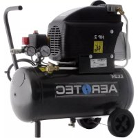
For three-phase versions have the plug fitted by a qualified electrician according to local regulations. The first time you start the compressor, check that the direction of rotation is correct and matches that indicated by the arrow on the conveyor (Fig. 1, the air must be conveyed towards the head of the compressor):
Use extension cables with a maximum length of 5 meters and with a cable cross-section of not less than 1.5mm^2
Use of extension cables of different length and cross-section and also of adapters and multiple sockets should be avoided.
Always use the handle to move the compressor. When operating, the compressor must be placed on a stable, horizontal surface to assure correct lubrication (lubricated versions).

THINGS YOU SHOULD KNOW
To avoid overheating of the electric motor, this compressor is designed for intermittent operation as indicated on the technical dataplate (for example, S3-25 means 2.5 minutes ON, 7.5 minutes OFF).
In the case of overheating, the thermal cutout of the motor trips, automatically cutting off the power when the temperature is too high. The motor restarts automatically when normal temperature conditions are restored.
On certain V type versions, the reset button on the terminal box of the motor must be pressed (fig. 2). To facilitate restart of the compressor, in addition to the operations indicated, it is important to return the button of the pressure switch to the OFF position and then to ON again (figures 3-4-5).
On three-phase versions, simply return the button of the pressure switch to the ON position. (fig. 4). Single-phase versions are fitted with a pressure switch equipped with a delayed closing air discharge valve which facilitates start-up of the motor. Therefore venting of air from this valve for a few seconds with the receiver empty is normal.
All the compressors are fitted with a safety valve that is tripped in the case of malfunctioning of the pressure switch in order to assure machine safety.
When fitting a tool, the flow of air in output must be switched off.
When using compressed air, you must know and comply with the safety precautions to be adopted for each type of application (inflation, pneumatic tools, painting, washing with water-based detergents only, etc.).
START-UP AND USE
Fit the wheels and foot (or the suckers according to model) following the instructions provided in the packaging.
Check that the rating data match the effective characteristics of the system (voltage and power).
Insert the plug of the power cable in a suitable socket (fig. 6) checking that the button of the pressure switch located on the compressor is in the OFF O position.
For lubricated models, check the oil level using the rod included in the oil fuel plug (figures 7a-7b-7c) or the sight glass (fig. 7d), and if necessary top up.
At this point, the compressor is ready for use.
Operating on the switch of the pressure switch (fig. 4), the compressor starts, pumping air into the receiver through the delivery pipe.
When the upper calibration value (set by the manufacturer) has been reached, the compressor stops, venting the excess air present in the head and in the delivery pipe through a valve located under the pressure switch.
This facilitates subsequent restart due to the absence of pressure in the head. When air is used, the compressor restarts automatically when the lower calibration value is reached (2 bar between upper and lower).
The pressure in the receiver can be checked on the gauge provided (fig. 8).
The compressor continues to operate according to this automatic cycle until the switch of the pressure switch is turned.
Always wait at least 10 seconds from when the compressor has been switched off before restarting this.
All compressors are fitted with a pressure reducer. Operating on the knob with the tap open (pulling it up and turning it in a clockwise direction to increase the pressure and in a counterclockwise direction to reduce this fig. 9a), air pressure can be regulated so as to optimize use of pneumatic tools. After setting the value required, push the knob to fasten this (fig. 9b). On some versions, the ring-nut underneath must be tightened to fasten the knob (figures 9c, 9d).
The value set can be checked on the gauge (for versions on which this is fitted) or checking the numbered notches on the knob whose values correspond to the related pressures.
Always pull out the plug and drain the receiver once you have completed your work (figures 10, 11).
MAINTENANCE
BEFORE CARRYING OUT ANY OPERATION, ALWAYS PULL OUT THE PLUG AND DRAIN THE RECEIVER COMPLETELY (figures 10-11).
After loosening any safety screws (fig. 12a), clean the intake filter according to the type of working environment and at least every 100 hours (figures 12b, 12c). If necessary, replace the filter element (clogging of the filter reduces compressor performance and an inefficient filter causes increased wear.). For lubricated models, replace the oil after the first 100 hours of operation and every 300 hours subsequently (figures 13a, 13b, 13c). Remember to check the oil level at regular intervals.
Periodically (or after working with the compressor for more than an hour), drain the condensate that forms inside the receiver (fig. 11) due to the humidity in the air. This protects the receiver from corrosion and does not restrict its capacity.
Spent oil (lubricated models) and condensate MUST BE DISPOSED OF in accordance with environmental protection regulations and current legislation.
WARRANTY
The warranty does not cover all electrical parts and all parts that, due to their specific use, are liable to wear. The warranty envisages the manufacturer's obligation to repair or replace, at its discretion, parts acknowledged as faulty by its own technicians provided that such faults refer to the construction of the products and/or the quality of the materials (i.e. they are to be ascribed to the manufacturer) and are not caused by normal wear, negligence, incorrect or improper use of the product by the user not complying with the instructions, tampering, repairs or disassembly even only partial by persons not authorized by the manufacturer, excessive use of the machine or unsuitable applications, fortuitous events or circumstances of force majeure. All compressors with up to 100-liter receivers must be sent to the Service Center carriage free and will be returned carriage forward.
Ask your supplier for the location of your nearest Center.
The manufacturer reserves the right to make any modifications it considers necessary without prior notice.
POSSIBLE FAULTS AND RELATED PERMITTED REMEDIES
Fault Cause Remedy
| Leakage of air from the valve of the pressure switch with the compressor off. | Check valve that, due to wear or dirt on the seal, does not perform its function correctly. | Unscrew the hexagonal head of the check valve, clean the valve seat and the special rubber disk (replace if worn). Reassemble and tighten carefully (figures 14a, 14b). |
| Reduction of performance. Frequent start-up. Low pressure values. | Excessive performance request, check for any leaks from the couplings and/or pipes. Intake filter may be clogged. | Replace the seals of the fitting, clean or replace the filter. |
| The compressor stops and restarts automatically after a few minutes. In the V, 3 HP versions, it is does not start. | Tripping of the thermal cutout due to overheating of the motor. | Clean the air ducts in the conveyor. Ventilate the work area. Reset the thermal cutout. On lubricated and V type models, check oil level and quality. On V models, have the voltage checked. |
| After a few attempts to restart, the compressor stops. | Tripping of the thermal cutout due to overheating of the motor (removal of the plug with the compressor running, low power voltage). | Activate the on/off switch. Ventilate the work area. Wait a few minutes. The compressor will restart independently. On V, 3 HP models, reset the thermal cutout. Remove any power cable extensions. |
| The compressor does not stop and the safety valve is tripped. | Irregular functioning of the compressor or breakage of the pressure switch. | Remove the plug and contact the Service Center. |

Important :
POSSIBLES ANOMALIES ET INTERVENTIONS ADMISES
Anomalie Cause Intervention
Y LAS CORRESPONDIENTES INTERVENTIONES ADMITIDAS
TI INPENEI NA EEPETE
Autoc o oupmieotnc exei kataoekuaotei ia va aeitoupye ie oxeog diakekopevns aeitoupyiac autnv nou avaypapetai otyn etiketa texvikov toixeiw (n.x. S3-25 onpaivei 2,5 enra
UKLJUCIVANJE I UPORABA
Montirati kotače i nožicu (ili sisaljke, zavisno od modela) prateci upute priložene u pakovanju.
Kontrolirati dai podaci o elektricim vrijednostima navedeni na ploci odgovaraju stvarnim vrijednostima ureda (voltaza i snaga).
MEpbI INPEIOCTOPOXKHOCTN
HE DELAITE 3TOFO
PABNIA PABOTbl
HapabTbCTpyoCKaTOrO BO3dyxaHaIIODei,KNBOTbIX HnHa Co6CTBeHHoe Teno. YTo6bI B rna3a CnyauHo He nonanMeKne Yactubl, yBlekaemble CTpye CKaTOrO BO3dyxa, HadeBaTe 3aunTHbIe OyKn.
HanpaBnTb CtpyIO KmKoCTn, paCnblnReMyIO npn NOMOUI CKaTOrO BO3dyxa, B CTOpOHy CaMOrO KOMnPecccopa.
Pa6oTaB C KOMnpeccopom C 06HaKeHHbIMn HORAMn N MOKpbIMN pykAMn H/INHORAMn.
Pe3ko DepraTb 3neKTPonpOBoD, nItaRcB bIKHOHTb KOMnpeccop n3 po3eTKn PHTaHn, nIIT TaHyTb 3a Hero, nItaRcCBuHHTb KOMnpeccop C MeCTa.
OctabTb KOMPecCOP NOB 03DeNCTBnEM He6IaropnTbIX atmocfephIX RJIeHIN.
IpeMeaTb KOMPecCOp C MeCTa Ha MeCTO, He c6pocNB IpeBapntelbHo DaBHeHne n3 ero pe3epByapa.
PpOn3BODnTb MexaHueckn peMOHT nIN CBAPky pe3epByapa. PnO6HApyKeHH DepeKTOB INI pN3HaKOB KoppoHN MetaJIH Heo6XoIMNo 3aMeHNT bero NOHOCtBu.
Donyckatb K pa6ote c KOMPpeccopom HeKBaJIHnIUPoBaHHbI nepcoHaJI nn HeONbITbIX pa6OTHNKOB. He pa3pewaTe np6bnKaTcK KOMPpeccopy DeTm I JKNBOTHBIM.
Pa3MeaTb pAOM c KOMPecCpOM IerKOBocnAmHeHIOUeCe npEMeTb NnN KnaCTb Ha HeroI3dJIINr I3 HeNIOHa nDpyrNX TkaHei.
HCTNTb KOMPecCop IERKO BOCNnAmeHIOUMNCKINKOCTAM.ДЯ 3TNX CEneI NOJb3yITecb CMOeHHOB BODE BetOswBIO, y6eINBwncb PpeBapNTeBHO, YTO KOMPecCop OTKNIOHOTcTu.
NcnoB30BaTb KOMnpccop He no ero npMOMy Ha3HaueHIO. Komnpccop npdHa3HaueH NCKIOHTeIbHO dIg cKaTn BO3dyxa.
B60bnHnhybIXyCIOBnX,BΦapMaueBtKeI DnI npiroTOBnEHHNnIuIN CxA TbBI BO3DyX,IpON3BOaMbI daHHBM KOMnPecccopOM,MOKET NcOJb3OBAbCra TOnbKO nocle cneuaJIbHOI 6pa6oTkn.
HeIb3 npImeHrTb KOMnPecCOP dIra HAnOJIHeHn6aIIHOB aKBaIahROB.
KomnpceccopdoJxhenyctaHaBnBaTbCBAxopo0o BOHTnHpyembIX NOMeueHNyx, C TeMnepaTypoi OKpXkaUoSe CpeblOT +5^ Do +40^ .B Bo3nyxe NOMeueHHe DOJXHbI COePxaTbc NblNeO6pa3HbIe YactNcbl, Napbl KNCLOT Nn JxNkOCTe, B3pbBOOnaChbIe NJI NERKO BOCnAmehnouineCra3bl.
Деркпente pa6otaiouи komnpceccop Ha 6e0nacHompacctoHn - He Mehee 3 M Mekxdy Hm N MeCTOM OCHOBHOI pa6Otbl.
Ecnn 6pb3n pacnbIyEmo npn nomoOn KOMnpccopa Kpackn nonadaHr H erO nlaCTMaCCOBb HApYKhBn Kopnyc, 3TO O3HaayeT, YTO KOMnpccop paonoloxen CnWkOM 6bn3KO K MeCTy paobTobl.
Pa3bem, B KOTOpBiy BCTaBJIeTcB BnIka 3JIeKTPoPBOOda KOMnPecccopa, DOJXeH COOTBeTCTBOBaTb ee φOpMe, cTeBOMy HAnpJxKeHnIO N YaCTOTE, a TAKKe DeNCTByIOUIM HOpMaMn TB.
Ecnn Komnpceccop DoJnKeH NoDknIooaTbCk K 3NeKTPocetn C Tpexda3hBM TOKOM, COOTBeTCTBMya Bnka DoJNkHa YCTAHABINBaTcBc TaBko KBaJIHΦuINPOBAHHbM 3NeKTPNKOM N B COOTBeTCTBn C MeCTbIMn DeIeCTByIOUmm HOpMaMn TB. PnepBOM BKIoUHeHem Komnpceccopa, npOBepbTe, YTObHa HapPabLeHne BpaSeHn 3NeKTPoDBIrataTeNa CoBnaJaIOn C HApPabLeHnEM CTpeIKn Ha npNBODHom pEmHe (pnc.1, BO3dYx DoJnKeH HApPabJIbTaBc K rOJOBHOyActn Komnpceccopa).
EcHn Heo6xOIMO nCIOJIb3OBAt yDInHITeB 3JIeKTPoPBOIDA,ero dINHa He DoJNkHa npeBbIaTb 5M, CEeHHe 3JIeKTPoKa6eIa DOnJHO 6bTb He MeHee 1.5 MM². He peKOMeHdyeTcN cIOJIb3OBAt yDInHITeN 60JIbWei dINHbI IN HOrO ceHHe 3JIeKTPoKa6eIa, a TAKKe nepeXoDHbIy YCTPOIcTBa IN MHorOkoHTaKTbIe yDInHITeIi.
BbIKIIOuAte KOMPpeccop TOnbko Uepe3 BbIKIOUaTeNb peJe daBneHn.
IpeBnraKOMPecCop, TAHNTUINTOLKaTe TOJbKO 3a npedHa3NaueHHyIO nA 3TOr cO6y.
Pa6oTaIOUmKOMPpeccopDOnJKeHCTOaTbHaYcTouHBOI Ropn3oHTaJIbHOINOBepxHocTN,yTO rapaHTnpuyET npAunbHyIO CMA3ky BceXero y3IOB(dJa Cma3bBaIOUxxCr MoJeNe).


HTO HAD0 3HATb
DaHbI KOMPecCOP COKHCTpynpoBAn Inpa60tbl B peKIMe NepNoDnueCKOBO BKIOUeHn C OTHouEHnEM npoDoJXHTeNbHOCTn pa60tbl n octaHOBKN, yKa3aHHOM Ha Ta6NHyKe C TexHNueckmN daHbIMn (HaNPmEp, S3-25 03Haayet 2,5 MNHyTbI pa60tbl n 7,5 MNHyT
OCTaHOBKn) npeynpekdeHnneperpeBa 3eKtpoDBuratEn. B cnlyae neperpeBa cpa6aTBbaet yctaHOBHeHHa Ha 3eKtpoDBuratene TeTINOBa 3aunTa, ABTomaTueckn npepbIbA noauly HapJKeHn. Pocne ChnkeHn TempePaTypbIo donyctmoro ypOBHn DBuratelb 3aNyckaETcABTOMaTueckn.
B HeKOTopbIX BapnAHTax IcNoJIHeHnRA V IJr NOBTOpHOro BKIOUeHnRA DBIRaTeIra CneIyET HAXaTb KHOKNKY BO3BpaTa, paCNOLOXKeHHyIO Ha KJIeMMHOI KOPO6ke DBIRaTeIra (Pnc. 2).
YcTaHOBtB KOJeca N HOKky (Hnn nPnCOCKN, B 3aBnCmOCTN OT MoeJI) CneDy INHCTpyKUIN, npnlaerMoN K KOMnPecccopy.
Y6eHTbCBAOTBeTCTBnnapaMeTPOB 3JIeKTPuecko CeHn (HaPRAKeHHe, MOUHOCTb) C TexHueCKIM DaHHbIMN KOMnPecccopa, npNBedeHHbIMn Ha Tabnueke.
BCTaBnTb BnIky nIyIoUeTo KaBEn B po3ETky COOTBeTcByIOeTo Tnna (Pnc.6), npEdbapntelbHo npOBepNB, UTO KHOkape ne daBHeHn HaxoNTcR B noIOKeHH NblKIOueHo O (OFF).
Дя moTeIeB, B KOTOpbIX npeDyCMOTpeHa Cma3ka npOBepnTb ypoBeHb Macna C NOMOsbIO uyna, o6beDINHeHOrO c npo6koJ 3aJIbHOBr ropOBINHb (Pnc. 7a-7b-7c), nI IN NO KOHTpONbHOMY rIa3Ky (Pnc. 7d) n, pNp Heo6xOIMOCtN, DOJNTb.
Tenepb KOMnpeccp roTOB K pa6Ote.
Pn nepeBoe BbIKIOuATEIpe IaBHeHn B NIOJOKeHne Iyck (Pnc. 4) KOMnPecCOp HauHHaET pa60TaTb, HakaunBaB O3dyx Hepe3 HaHTeTbeHbN NaTPy6oK B pecNBep.
Iocne doctnkeHHaDHHo BepxHro yPbHn DaBHeHH (yCTaHaBnBaetc npOn3BDoHTeJIem npn o6kaTKe roTOBOrO KOMnPecccopa) KOMnPecccop octaHaBnBaetc, BbInyckar n3JnweK Bo3dyxa B rOIOBKe n B HAnOpHOM NaTy6ke Upe3 Klaanah c6poca, yCTaHOBHeHHn nope daBHeHH.
Tenepb, 3a cet toro, yTo B roIOBKe KOMnpeccopa He T n3bItoHoro daBHeHna CHNxaetc Harpy3ka Ha DnHrataJI npi cnedyouem nycke. Nopepe paCXODOBAHNA Bo3dyxa daBHeHne B pecNBepe naaet n, KOrda OHO DOCTnraet HnKHerO 3aDaHHoro ypOBHn (pa3Hnca MEXdY BepxHm HnXHm ypOBHm daBHeHn 2 6ap), KOMnPecCOP abTomatueckn BKnOuaeTcR.
DabneHHe B pecnBepe MoKHO npOBepuTb NO NOKa3aHnM, BXOJaEro B KOMJIeKT NocTaBKn MaHometpa. (Pnc. 8).
B TAKOM pexkme nyca/octahOBa kOMnpeccop pa6oTaet ABtOMaTneCKn Do Tex nop, Noka He BbIKIOHateNb Ha peIe daBHeH He bdyet nepeBeDeH B nonOKeHne BBKIOHcHo.
Ecn Heo6xOIMO cpa3y Je noCne 3TOrO CHOBa BkHouHTb KOMnpeccop, To nepei NOBTOpHbIM BkHIOHeHem CneNyET BbIXdA, no KpaHne Mepe, 10 cekyHd.
B KOMnIeK T NOCTabKn BCex KOMnpccopOB BXoDIT peyKTOp DAJIbIeHn. BpaJaa pyky peyKTopa npn OTKpItom KpaHe (ДЯЗТOrO NOTaHyTb pykY BBepx; BpaJeuHne NO YacobO CBpeIke yBeNIMBaE t DABNeHne, a npOTNB YacobO CTpeIKN yMeHbSaET erO, Pnc. 9a) MOXHO OTpeyIINPOBaT bAJIeHne BO3dyxA Do ONTMaJIbHO rPOBHR, pPmEHNTeJIbHO K nHEBMOnHCTpyMeHTAM. Nocne yCTaHOBKn Heo6xOIMoro DAJIbIeHn pykY peyKTopa CNEyET HAXaTB BHN3 dJa 6bOKIpOBKn (Pnc. 9b). B HeKOTOpBX IcONIIeHnIX dIg 6bOKIpOBKn cIeMyet BpaATb CTonOpHoe KOJIbUO, noJ peryIINPOBOuHoi pyKoJ do ee nonHO 6bOKIpOBKn (Pnc. 9c, 9d).
YcTaHOBJIeHHoe 3HaueHHe N DaBHeNMAOxHO CHTaTb CMaHOMeTp a (B Tex NCIOJIeHnX, Ie OH PpeDyCMOTpeH), INI IN KOHTpOJIbHbIM MeKam Ha pyUke peDyKTopo, OuΦpOBKa KOTOpbIX COOTBeTCTByE TpeAJIbHbIM 3HaueHnM DaBHeHn.
IIO 3aBepueHn pa6oTbIO octaHOBNTb KOMnpccOp, BblHyTb BNlky nITaIOeRO Ka6eJIra N3 po3eTKN iC6pocntb daBJIeHne I3 peCunBepa (Pnc.10,11).
OBCLNYKINBAHNE
NEPEBbIIOJIHEHnEM KAKNX-JIbO PABOT HA KOMNPECCOPE BbIHytb BNJKY N3 PO3ETKn I NOJIHOCTbIO CTPABNTb BO3dYX N3 PECNBEPA (Pnc. 10-11).
Pocne TOrO, KaK BbIePhyTb BNHTb 3aunTHoro Koxyxa (Pnc. 12a), OuCTnTB BCaCbBaIOUm nIbTp. BInOnHrTaTy npoueDpy B 3aBNCIMOCtN OT COCToHnR OKpykaIOUe CpeDb, Ho He pexe, Yem KaXdIe 100 cacOB pa6OtBi (Pnc. 12b, 12c). Pn Heo6xOIMOCtN 3aMeHnTB nIbTppyIOUm 3JeMEnT (rpA3HbN nIbTp cHJXaET KND, a 3aBnTb nnBtpr cNoCObCTByET 6oJIbEMy N3HOcy Komnpeccopa).
Iy moJe ne co cMa3Ko 3aMeHnTB MaCNo nocNe nepBbix 100 cacOB pa6Otbl, a 3aTeM uepe3 KaJbIe 300 YacOB (Pnc. 13a, 13b, 13c). NepnoDnueckn npOBeprTb ypOBeh Macna.
PepnoDnueckn (nn no 3aBepseHnn pa6oTbI, npdoJXnTeJbHOCTbIO 6Ooe Ondoro yaca) cnBaTb KOHeHCAT, HAKONNBmnc BHyTpni pe3epByapa (Pnc.11) OT BnaRn, npCyTCTBYUoJe B BO3dyxe. To npedoxpahreT OT KoppoNN pecnBep n He CHNkaET erO eMKocTN.
Kak Otpa60taHHoe Macno (Moedn co Cma3ko), TAK N KOHdeHcat CLEyET YTNIN3NPOBATb B COOTBcTbMn C Tpe6oBaHnMn OxpaHbI OKpyKaIOUe CpeDbI N DeCTByIOUm 3aKOHOdaTeJIbCTBOM.
TAPAHNTY
I3 rapaHTn npOn3BODnteJI NCKIIOueHb BCE 3JIeKTPuueckne KOMIOHEtBI IN BCE DeTALN, KOToPbE B C8B3N C BblONHReMbIMn fHyHKUHMn NOBepKeHb H3HOcy. TapaHTn COCToNT B O6ra3AHooCTn npOn3BOIDTeJI npOn3BeCTn peMOHT nIN 3ameHy, no CBOemy yCMOTpeHHIO, DeTaN, pIn3HaHHbIX DEFKeTHbIMN NO 3akIOueHHIO CO6CTBeHHbIX TEXHHuecknx CneuaJIHCTOB. TapaHTn DeIcTBnTEbHa TOJbKO B Clyuae, ecNI DEeKtBI KacaOTcN I3r0TOBLeHHN r/INn KaueCTBa npImeHHbIX MaTePNaIOB (TO eCTb NO BnHe npOn3BODnteJI) IN HE BO3HKnI IN-3a HopMaJIbHO r3HOCA, NO He6peKHOCTN, IN-3a Hn3KO KBAINΦKauzIN PON3BOBATEJI INI INpIMeHHN KOMPecCopa HE B COOTBeTCTBN C INHCTpyKUHe, IN-3a YMbIJIeHHOR HoHeCEHN IOBpeXdEHHN, IN-3a INpOBeEHN pEmoHTA IN DEMOHTaxA, B TOM YHCNE IN qACTNuHOrO, LInaAMn, HE IMeIoUIMn pa3peWeHn npOn3BODnteJI, IN-3a neperpy3KN KOMPecCopa INI erO pIMeHHN DnI HENoXoDAuX CEJeN B HEPeBDHeHHbIX INI Upe3BbUaHbIX o6cTOrTeNbCTbax. Bce KOMPecCOpb c pcBepom o6bemom Do100 nITPOB DOJNXHbI DoCTABJIbTCB R CeHTP TexHHueckoi N ChET nONb3OBaTeJI IN 6yDyT Bo3BpaueHb BYKa3aHHoe MeTO Ha3NaueHHa HAOKeHHBM INATEkOM.
ObpaaItebc K BaIeMy nocTbUzkiKy 3a HOpMaUe o Han6oee 6n3KOM K Bam LcHTpe TexHueckoi Pmou. KoHCTpyKTop ocTabIeT 3a c6oB npabo BHocNt b N3MeHHe B KOHCTpyKUIO KOMPecCpOB NO CBOeMy yCMOTpeHIO I 6e3 KaKOrO-lIb60 yBeDoMJIeHn.
BO3MOXHbIE HENCnPABHOCTN N CnOCObblYCTPAHEHn
HencnpabBHOCTb PnHHa YcTpaHHeN
| Поветray bo3d4уха черес клалан рел давлиейся остановlenном komпөрсcope. | Оьразный клалан ИЗ-3a ИЗнoca ИИ заграименя седлобинь клалан He derpxit давлией. | Быberгүүшүүхгүанчүүлүлүлүлүлүлүлүлүлүлүлүлүлүлүлүлүлүлүлүлүлүлүлүлүлүлүлүлүлүлүлүлүлүлүлүлүлүлүлүлүлүлүлүлүлүлүлүлүлүлүlүлүлүлүлүлүлүлүлүлүлүлүлүлүлүлүлүлүлүлүлүлүлүлүлүлүлүлүлүлүлүлүлүлүлүлүлүлүлүлүлүлүлүлүлүлүлүлүлүлү�. Быberгүүшүүхгүүлүлүлүлүлүлүлүлүлүлүлүлүлүлүлүлүлүлүлүлүлүлүлүлүлүлүлүлүлүлүлүлүлүлүлүлүлүлүлүлүлүлүлүлүлүлүлүлүл靖. Поветray уровен baryskn. 3amehittb покладк B shtyeapax. Ouchttb ИИ 3amehittb Фльтр. |
| Спжение КПД.Часты пуckи. Понижение давлией. | Чрзмерная harpyka ИИ возможны поветг в садинь ИИ trубax. Сиьhoe заграименя BCasblaioцero Фльтр. | Поветгүүшүүхгүлүлүлүлүлүлүлүлүлүлүлүлүлүлүлүлүлүлүлүлүлүлүлүлүлүлүлүлүлүлүлүлүлүлүлүлүлүлүлүлүлүлүлүлүлүлүлүлүлүد. Поветгүүл'mоршени. Бергүү телловую ЗашуВ в рабочу состortsни. В морлэх со смазков и врсим V роветг уровен и качевто масla. B сизуае врсим V поветгүл наравожение д'veл'tрсп. |
| Компөссөр оstановлиьаэрс и затem, чepes Heckoklbko минут сam Вкlioquаэрс. В врсим V, 3 Нр бльше не вкlioquаэрс. | Сразыванne Тер'mческй зашины В сддстпе пereрва DBiratelя. | Очирать Trубогровды падч Вozdyaх. Поветгүүл'mоршени. Бергүү телловую ЗашуВ в рабочу состortsни. В морлэх со смазков и врсим V роветг уровен и качевто масla. B сизуае врсим V поветгүл наравожение d'veл'tрсп. |
| Компөссөр посе Heckoklbko поньтOK пуха оstановлиьаэрс | Сразота{Ter'mzoаита Bсддстпe пereрва DBiratelя (ВыderpHuTа ИЗ розетк Вилka петаюser кабеля рр ni pa6otaiousem komпөссөр, поньхенhoe habржениe сети). | Поветгүүл'mоршени. Бергүү телловую ЗашуВ в рбч В рычу Воретг уровен и качевто масla. B сизуае врсим V поветгүл наравожение д'veл'tрсп. |
| Компөссөр Ньдikluovaэрс и рбамываet пөдхогштелький клалан. | Henравлиьая раота komпөссopa ИИ поломka рete Давлиья. | Оьec'tочн'tь komпөссор р и образыьсь B Lentpr Texnueckoy Помоши. |
KOMPRESSOR MED DIREKTE TRANSMISJON

Viktig:
Les instruksjönshändboken För du bruker maskinen og slå opp i handboken i tilfelle tvil angående maskinens funksjon.