BELLE BULLDOG - Generator ALTRAD - Free user manual and instructions
Find the device manual for free BELLE BULLDOG ALTRAD in PDF.
| Product Type | Hydraulic Power Pack (Hydraulic Generator) |
| Brand | Altrad Belle |
| Model | BELLE BULLDOG |
| Engine | Honda GX270 (gasoline) or Lombardini 15LD 350 (diesel) depending on version |
| Engine Power | 9 HP (Honda) / 7.5 HP (Lombardini) |
| Hydraulic Flow Rate | 20 L/min |
| Operating Pressure | 140 bar (standard version) |
| Dimensions (L x W x H) | 740 x 555 x 620 mm (Midi version) |
| Dry Weight | Approximately 60 to 67 kg depending on version |
| Hydraulic Oil Tank Capacity | 6.2 L |
| Fuel Tank Capacity | 6 L (gasoline) or 4.3 L (diesel) |
| Fuel Type | Unleaded gasoline or diesel depending on version |
| Sound Level | 104 dB(A) |
| Hydraulic Couplings | 3/8" / 1/2" flat face quick couplings |
| Hydraulic Oil Type | ISO VG T32 (temperature <30°C) or ISO VG T46 (temperature >30°C) |
| Applications | Powering EHTMA category C (green triangle) hydraulic tools: breakers, submersible pumps, etc. |
| Safety | Engine protection, emergency stop, by-pass, safety labels, personal protective equipment required |
| Maintenance | Regular checks (10h, 50h, 100h, 300h): levels, filters, hoses, cooler |
| Warranty | 12 months for the original purchaser, excluding normal wear and consumable parts |
Frequently Asked Questions - BELLE BULLDOG ALTRAD
User questions about BELLE BULLDOG ALTRAD
0 question about this device. Answer the ones you know or ask your own.
Ask a new question about this device
Download the instructions for your Generator in PDF format for free! Find your manual BELLE BULLDOG - ALTRAD and take your electronic device back in hand. On this page are published all the documents necessary for the use of your device. BELLE BULLDOG by ALTRAD.
USER MANUAL BELLE BULLDOG ALTRAD
natural_image
Technical line drawing of a mechanical device with internal components and mounting brackets (no text or symbols)- Spare Parts Book
• Pièces Détachées - Libro Despiece
- Lista de Peças
• Onderdelen Boekje - Reservedele Skrift
• Ersatzteilhandbuch
• Manuale dei Ricambi
• Bruksanvisning - Varaosaluettelo
- Lista Części Zamiennych
• Запасные Части Книга
• Varuosade Nimekiri - Rezerves Dalu Saraksts
- Atsarginiu Daliu Sarašas
• Част Списък - Část Barevný Pruh
• Lista Pieselór De Schimb
• Részek Oldalra Dől - Rezervni Djelovi Knjiga
258
GB Operators Manual
US Operators Manual
F Manuel De L'Opérateur
E Manual del Operador
P Manual de Operação
NL Handleiding
DK Betjeningsvejledning
D Bedienungshandbuch
① Manuale Dell'Operatore
s Bruksanvisning
SF Käyttöohje
PL Instrukcja Obstugi
RUS Руководство для оператора
EST Kasutusjuhend
LV Lietotāja rokasgrāmata
LT Naudojimo Instrukcija
BG Оператор Ръчен
cz Na'vod K Obzluze
RO Manual de Utilizare
HUN Kezelők Kézi
HR Uputstvo za rukovatelja
6
18
30
42
54
66
78
90
102
114
126
138
150
162
174
186
198
210
222
234
246
EC DECLARATION OF CONFORMITY / DECLARATION CE DE CONFORMITE / DECLARACIÓN DE CONFORMIDAD CE / DECLARAÇÃO CE DE CONFORMIDADE / EG-VERKLARING VAN OVEREENSTEMMING / EF OVERENSSTEMMELSESERKLÆRING

We, Belle Group Sheen UK, Sheen, Nr. Buxton, Derbyshire, SK17 0EU, GB, hereby certify that if the product described within this certificate is bought from an authorised Belle Group dealer within the EEC, it conforms to the following EEC directives: 2006/42/CE (This directive replaces directive 98/37/EC), Electromagnetic Compatibility Directive 2004/108/CE (as amended by 89/336/EEC, 92/31/EEC & 93/68 EEC). The Waste Electrical and Electronic Equipment (WEEE) 2002/96/CE, the low voltage directive 2006/95/CE, BS EN ISO 12100-1:2003 Safety of machinery and associated harmonised standards, where applicable. Noise emissions conform to directives 2000/14/EC Annex VI & 2005/88/EC, for machines under article 12 the notified body is AVT Reliability, Unit 2 Easter Court, Europa Boulevard, Warrington, Cheshire, WA5 7ZB, GB Noise Technical Files are held at the Belle Group Head Office address which is stated above.

PRODUCT TYPE ...... TYPE DE PRODUIT...... TIPO DE PRODUCTO......
MODEL...... MODELE...... MODELO......
SERIAL No..... N° DE SERIE..... N° DE SERIE.....
natural_image
Empty white rectangle with dashed border (no text or symbols)Signed by:
Signature:
Medido por:
Assinado por:
Getekend door:
Uunderskrevetaf:

text_image
O. NathRay Neilson
Managing Director - On behalf of BELLE GROUP (SHEEN) UK.
Date of Declaration - 2009....
natural_image
Empty white rectangle with dashed border (no text or symbols)Unterzeichnet vo:
Firmato da:
Undertecknat:
Signatur:
Allekirjoitus:
Podpisat:

text_image
O.NahRay Neilson
natural_image
Empty white rectangle with dashed border (no text or symbols)text_image
O.Nathi Ray Neilsonnatural_image
Empty white rectangle with dashed border (no text or symbols)Podepsal:
Semnat de:
Aláírás:
Potpisao:
imzalayan:
Podpísal:

text_image
O. Nath Ray NeilsonDirector General - in numele BELLE GROUP (SHEEN), UK
This manual has been written to help you operate and service the Hydraulic Power Pack safely. This manual is intended for dealers and operators of the Hydraulic Power Pack.
Foreword
The ‘Machine Description’ section helps you to familiarise yourself with the machine's layout and controls.
The ‘General Safety’ and ‘Health and Safety’ sections explain how to use the machine to ensure your safety and the safety of the general public.
The ‘Operating Instructions’ section helps you with the setting up and use of the machine.
The ‘Trouble Shooting Guide’ helps you if you have a problem with your machine.
The ‘Environment’ section gives instructions on how to handle the recycling of discarded apparatus in an environmentally friendly way.
The ‘Service & Maintenance’ section is to help you with the general maintenance and servicing of your machine.
The 'Warranty' section details the nature of the warranty cover and claims procedure.
The ‘Declaration Of Conformity’ section shows the standards that the machine has been built to.
Directives with regard to the notations.
Text in this manual to which special attention must be paid are shown in the following way:

CAUTION
The product can be at risk. The machine or yourself can be damaged or injured if procedures are not carried out in the correct way.

WARNING
The life of the operator can be at risk.

WARNING

WARNING
Before you operate or carry out any maintenance on this machine YOU MUST READ and STUDY this manual.
KNOW how to safely use the unit's controls and what you must do for safe maintenance.
(Be sure that you know how to switch the machine off before you switch on, in case you get into difficulty.)
ALWAYS wear or use the proper safety items required for your personal protection.
If you have ANY QUESTIONS about the safe use or maintenance of this unit, ASK YOUR SUPERVISOR OR CONTACT THE Altrad Belle+44 (0)1298 84606

Contents
How to use this manual....6
Warning 6
Machine Description....7
Applications 7
Decals....8 - 9
Technical Data....10
General Safety 11
Health and Safety....11
Pre-Start Safety Checks....11
Operating Instructions....12
Trouble Shooting Guide 13
Service & Maintenance 14
EHTMA - Code Of Practice 15
Environment 15
Options - Tool Tray 16
Warranty 17
Declaration of Conformity....2
text_image
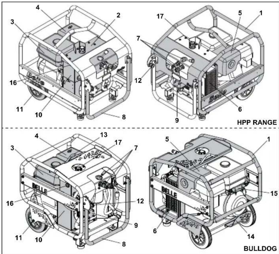
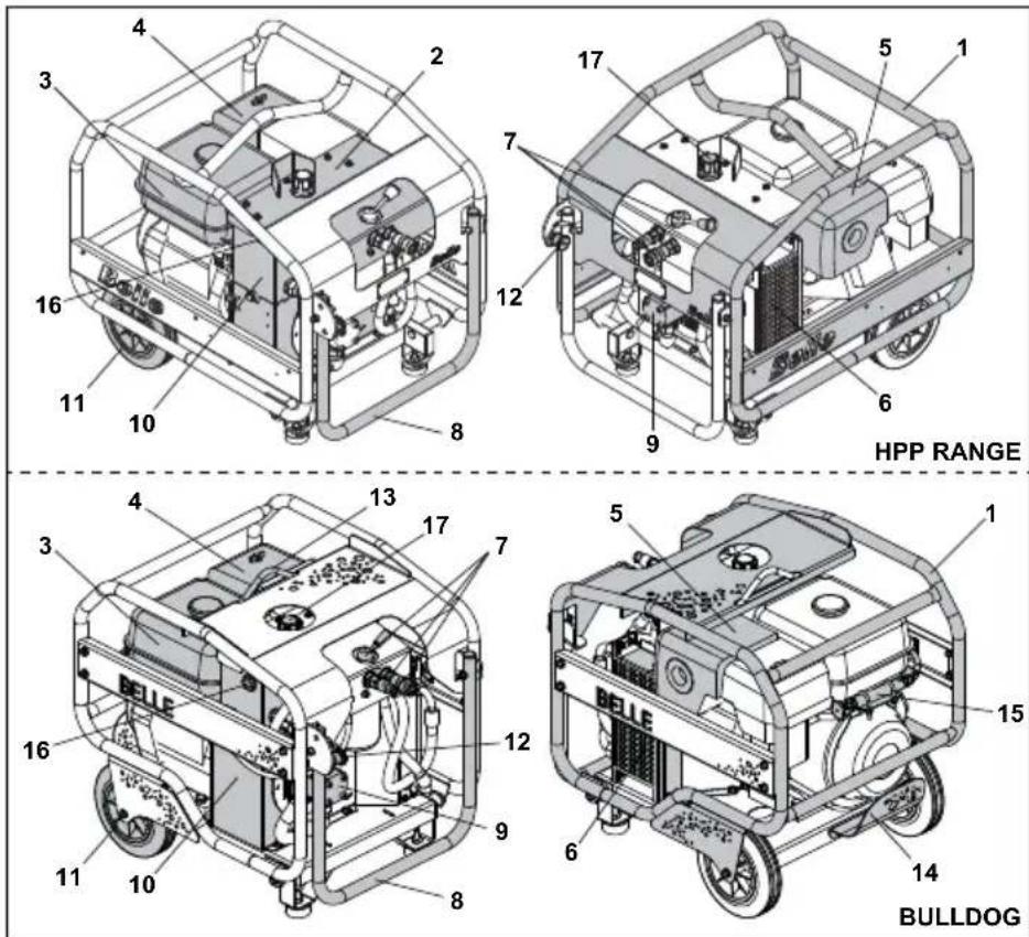
HPP RANGE BULLDOG- Frame
- Cowl
- Fuel Tank
- Air Filter
- Exhaust
- Oil Cooler
- Valve Block
- Transport Handle
- Pump
- Hydraulic Oil Tank
- Transport Wheels
- Handle Latch
- Lifting Eye
- Engine Protection
- Power on Demand (POD) System.
- Hydraulic Oil Sight Glass
- Hydraulic Oil Filler Cap
Applications

The Altrad Belle Bulldog Power Pack is suitable to power the following Altrad Belle hydraulic tools.
a) BHB12 12 Kg. Hand held Pick. b) BHB19 19 Kg. Hand held breaker. c) BHB23 23 Kg Hand held breaker. d) BHB25 25 Kg. Hand held breaker. e) BHB25X 25 Kg. Hand Held Breaker f) 2322-S Sub Water Pump.
The Bulldog Power Pack can safely be connected to any tool which carries the EHTMA Category 'C' (Green Triangle). If in doubt regarding the correct and safe connection of a tool please consult Altrad Belle, or your local Agent for advice.
The Altrad Belle Midi Power Pack is suitable to power the following Altrad Belle hydraulic tools.
a) BHB12 12 Kg. Hand held Pick. b) BHB19 19 Kg. Hand held breaker. c) BHB23 23 Kg Hand held breaker. d) BHB25 25 Kg. Hand held breaker. e) BHB25X 25 Kg. Hand Held Breaker f) 2322-S Sub Water Pump.
The Midi Power Pack can safely be connected to any tool which carries the EHTMA Category 'C' (Green Triangle). If in doubt regarding the correct and safe connection of a tool please consult Altrad Belle, or your local Agent for advice.
The Altrad Belle Major Power Pack MAJOR 20/140X & MAJOR 20/160X is suitable to power the following Altrad Belle hydraulic tools EHTMA Cat. 'C'.
a) BHB12 12 Kg. Hand held Pick. b) BHB19 19 Kg. Hand held breaker. c) BHB23 23 Kg Hand held breaker. d) BHB25 25 Kg. Hand held breaker. e) BHB25X 25 Kg. Hand Held Breaker f) 2322-S Submersible Water Pump.
The Altrad Belle Major Power Pack MAJOR 30/140 is suitable to power the following Altrad Belle hydraulic tools EHTMA Cat. 'D'.
a) BHB27 27 Kg. Hand held Pick. b) BHB 27X 30Kg. Hand held breaker. c) 188 Disc Cutter
The Major Power Pack can safely be connected to any other tool which carries the relevant EHTMA Category 'D' (Brown Triangle). If in doubt regarding the correct and safe connection of a tool please consult Altrad Belle or your local Agent for advice.
text_image
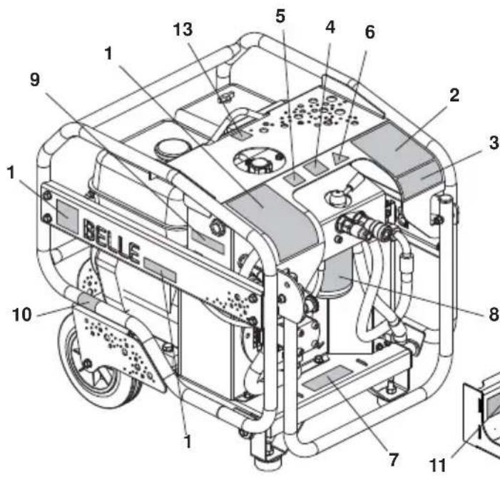
BELLE 1 2 3 4 5 6 7 8 9 10 1 13- Branding Decals
- Start / Stop Procedure Decal
- Safety Decal
- Noise Decal
- CE Decal
- EHTMA Decal
- Filter Condition Decal
- Filter Fitment Decal
- Oil Level Decal
- Engine On / Off Switch Decal
- Tool Tray Safety Decal
- Tool Tray Fitment Decal
- Lifting Eye Decal
1. Branding Decals
Indiates the make and model of the machine.
2. Start / Stop Procedure Decal
Gives instructions on how to Start and Stop the Bulldog Power Pack.
3. Safety Decal

Read the
Operators Manual

Wear Ear Protection

Wear Eye Protection

Wear Protective Footwear
4. Noise Decal
Indicates the Noise Level (dB(A)) of the machine.
5. CE Decal
Indicates that the machine is CE certifi ed.
6. EHTMA Decal
Indicates the EHTMA Rating, which identifies the hydraulic flow rate and working pressure of the machine
7. Filter Condition Decal
Gives servicing information for the hydraulic filter.
8. Filter Fitment Decal
Indicates how to change the hydraulic filter.
9. Oil Level Decal
Indicates the position of the hydraulic oil guage.
10. Engine On / Off Switch Decal
Indicates the position of the Engine On / Off Switch
11. Tool Tray Safety Decal
Gives safety instructions for using the tool tray correctly.
12. Tool Tray Fitment Decal
Gives instructions for fitting the tool tray to the machine correctly.
13. Lifting Eye Decal
Gives safety instructions for using the tool tray correctly.
text_image
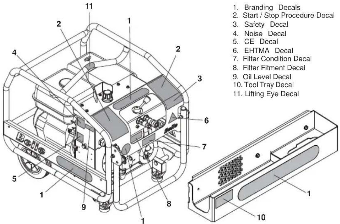
1. Branding Decals 2. Start / Stop Procedure Decal 3. Safety Decal 4. Noise Decal 5. CE Decal 6. EHTMA Decal 7. Filter Condition Decal 8. Filter Fitment Decal 9. Oil Level Decal 10. Tool Tray Decal 11. Lifting Eye Decal1. Branding Decals
Indiates the make and model of the machine.
2. Start / Stop Procedure Decal
Gives instructions on how to Start and Stop the Bulldog Power Pack.
3. Safety Decal

Read the
Operators Manual

Wear Ear Protection

Wear Eye Protection

Wear Protective Footwear
4. Noise Decal
Indicates the Noise Level (dB(A)) of the machine.
5. CE Decal
Indicates that the machine is CE certified.
6. EHTMA Decal
Indicates the EHTMA Rating, which identifies the hydraulic flow rate and working pressure of the machine
7. Filter Condition Decal
Gives servicing information for the hydraulic filter.
8. Filter Fitment Decal
Indicates how to change the hydraulic filter.
9. Oil Level Decal
Indicates the position of the hydraulic oil guage.
10. Tool Tray Decal
Gives safety instructions for using the tool tray correctly.
11. Lifting Eye Decal
Gives safety instructions for using the tool tray correctly.
| Model Bulldog 20-140 Midi 20-110D* Midi 20-140 | |||
| Engine Honda GX270 | Lombardini 15LD 350 | Honda GX270 | |
| Engine Power (Hp) 9 7 | 5 | 9 | |
| Hydraulic Flowrate (Ltrs/Min) 20 20 20 | |||
| Working Pressure (Bar) 140 110 140 | |||
| Length (mm) (With Handle Folded) 705 740 740 | |||
| Width (mm) 515 555 555 | |||
| Height (mm) | 620 620 620 | ||
| Hydraulic Connections | 3/8" / 1/2" | 3/8" / 1/2" | 3/8" / 1/2" |
| Flat faced, quick release, Non-drip couplings | |||
| Hydraulic Oil Type | -Below 30^ = ISO VG T32. - Above 30^ = ISO VG T46 | ||
| Dry Weight (Kg) | 59.5 | 67 60 | |
| Weight Including Oils (Kg) | 65.5 | 73 | 66 |
| Oil Tank Capacity (Ltrs) | 5.6 | 6.2 | 6.2 |
| Fuel Type | Unleaded | Diesel | Unleaded |
| Fuel Tank Capacity (Ltrs) | 6 | 4 | . |
| Noise Level (dB(A)) | 101 104 101 | ||
| Model | Major 20-140X | Major 20-160X | Major 30-140 |
| Engine | Honda GX390 | Honda GX390 | Honda GX390 |
| Engine Power (Hp) | 13 13 13 | ||
| Hydraulic Flowrate (Ltrs/Min) 20 20 30 | |||
| Working Pressure (Bar) 140 160 140 | |||
| Length (mm) (With Handle Folded) 740 740 740 | |||
| Width (mm) 555 555 555 | |||
| Height (mm) | 620 620 620 | ||
| Hydraulic Connections | 3/8" / 1/2" | 3/8" / 1/2" | 3/8" / 1/2" |
| Flat faced, quick release, Non-drip couplings | |||
| Hydraulic Oil Type | -Below 30° = ISO VG T32. - Above 30° = ISO VG T46 | ||
| Dry Weight (Kg) | 72 72 72 | ||
| Weight Including Oils (Kg) | 78 78 78 | ||
| Oil Tank Capacity (Ltrs) | 6.2 | 6.2 | 6.5 |
| Fuel Type | Unleaded | Unleaded | Unleaded |
| Fuel Tank Capacity (Ltrs) | 6.5 | 6.5 | 6.5 |
| Noise Level (dB(A)) | 101 101 101 | ||
* = Not CE Approved
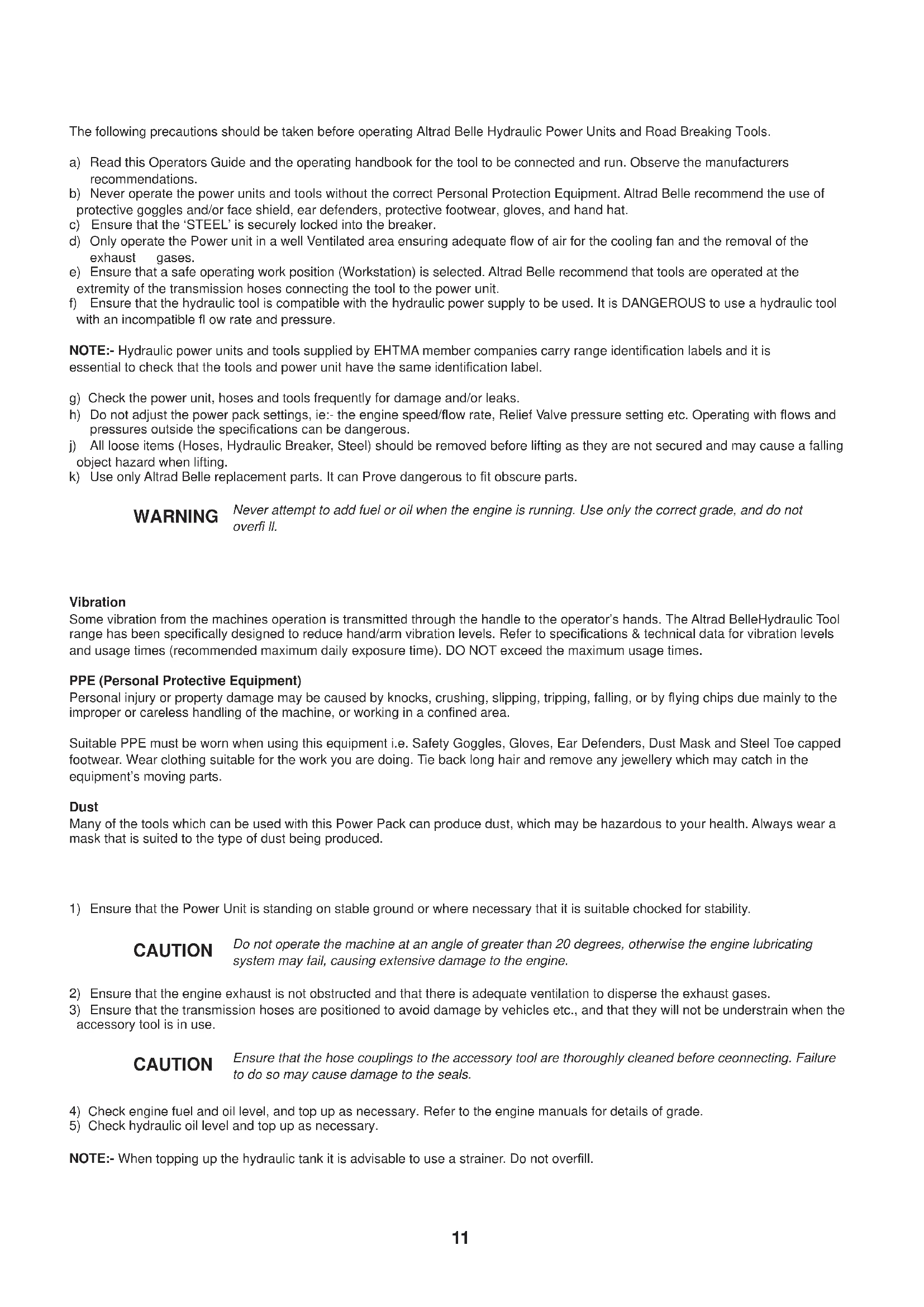
The following precautions should be taken before operating Altrad Belle Hydraulic Power Units and Road Breaking Tools.
a) Read this Operators Guide and the operating handbook for the tool to be connected and run. Observe the manufacturers recommendations.
b) Never operate the power units and tools without the correct Personal Protection Equipment. Altrad Belle recommend the use of protective goggles and/or face shield, ear defenders, protective footwear, gloves, and hand hat.
c) Ensure that the 'STEEL' is securely locked into the breaker.
d) Only operate the Power unit in a well Ventilated area ensuring adequate flow of air for the cooling fan and the removal of the exhaust gases.
e) Ensure that a safe operating work position (Workstation) is selected. Altrad Belle recommend that tools are operated at the extremity of the transmission hoses connecting the tool to the power unit.
f) Ensure that the hydraulic tool is compatible with the hydraulic power supply to be used. It is DANGEROUS to use a hydraulic tool with an incompatible flow rate and pressure.
NOTE:- Hydraulic power units and tools supplied by EHTMA member companies carry range identification labels and it is essential to check that the tools and power unit have the same identification label.
g) Check the power unit, hoses and tools frequently for damage and/or leaks.
h) Do not adjust the power pack settings, ie:- the engine speed/flow rate, Relief Valve pressure setting etc. Operating with flows and pressures outside the specifications can be dangerous.
j) All loose items (Hoses, Hydraulic Breaker, Steel) should be removed before lifting as they are not secured and may cause a falling object hazard when lifting.
k) Use only Altrad Belle replacement parts. It can Prove dangerous to fit obscure parts.
WARNING
Never attempt to add fuel or oil when the engine is running. Use only the correct grade, and do not overfi ll.
Vibration
Some vibration from the machines operation is transmitted through the handle to the operator's hands. The Altrad BelleHydraulic Tool range has been specifically designed to reduce hand/arm vibration levels. Refer to specifications & technical data for vibration levels and usage times (recommended maximum daily exposure time). DO NOT exceed the maximum usage times.
PPE (Personal Protective Equipment)
Personal injury or property damage may be caused by knocks, crushing, slipping, tripping, falling, or by flying chips due mainly to the improper or careless handling of the machine, or working in a confined area.
Suitable PPE must be worn when using this equipment i.e. Safety Goggles, Gloves, Ear Defenders, Dust Mask and Steel Toe capped footwear. Wear clothing suitable for the work you are doing. Tie back long hair and remove any jewellery which may catch in the equipment's moving parts.
Dust
Many of the tools which can be used with this Power Pack can produce dust, which may be hazardous to your health. Always wear a mask that is suited to the type of dust being produced.
1) Ensure that the Power Unit is standing on stable ground or where necessary that it is suitable checked for stability.
CAUTION
Do not operate the machine at an angle of greater than 20 degrees, otherwise the engine lubricating system may fail, causing extensive damage to the engine.
2) Ensure that the engine exhaust is not obstructed and that there is adequate ventilation to disperse the exhaust gases.
3) Ensure that the transmission hoses are positioned to avoid damage by vehicles etc., and that they will not be understrain when the accessory tool is in use.
CAUTION
Ensure that the hose couplings to the accessory tool are thoroughly cleaned before ceconnecting. Failure to do so may cause damage to the seals.
4) Check engine fuel and oil level, and top up as necessary. Refer to the engine manuals for details of grade.
5) Check hydraulic oil level and top up as necessary.
NOTE:- When topping up the hydraulic tank it is advisable to use a strainer. Do not overfill.
Take the Power Pack to where it is required.
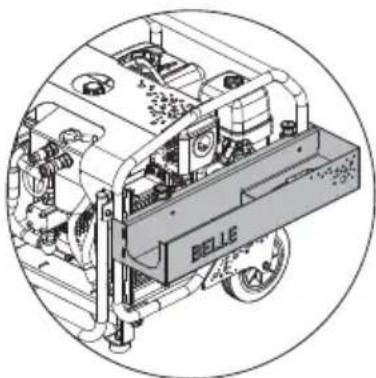
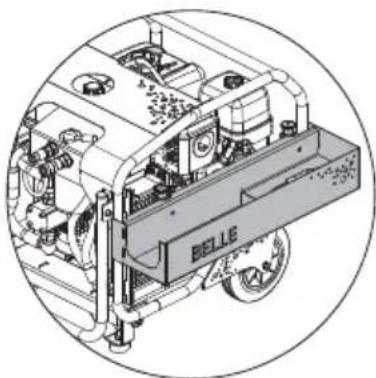
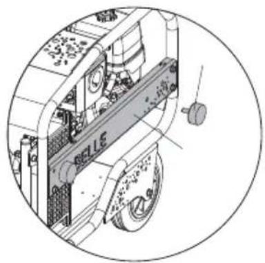
When using the wheels and transport handle ALWAYS ensure the handle latch is engaged before transporting the Power Pack (see image)
Where it is necessary to use lifting equipment to position the Power Pack, make sure the lifting equipment has a WLL (Working Load Limit) suitable for the Power Pack's weight (see Technical Data section or machine serial plate). Attach suitable chains or slings ONLY to the lifting point on the top of the Power Pack.
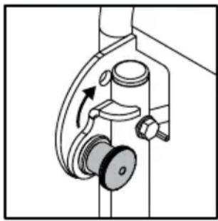
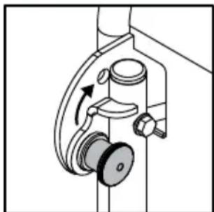
Starting the Engine
NOTE:- Refer to the engine manual for details. Always ensure the Bypass lever is in the Bypass position.
natural_image
Mechanical diagram showing a rotating device with a curved arrow indicating motion (no text or symbols)Petrol Engines
1) Open the fuel tap.
2) Close the choke on the carburetter.
3) Set the engine ignition switch to 'ON'.
4) Start the Engine by pulling on the recoil starter rope.
5) As the engine warms up, gradually return the choke to 'OPEN'.
NOTE:- Midi and Major petrol Power Packs are fitted with a Power On Demand device and the engine will run at idle speed until pressure is generated in the hydraulic system.
Diesel Engines
1) Open the fuel tap.
2) Set the engine speed control to the 'START' position.
3) Set the decompressor lever to the 'START' position.
4) Start the engine by pulling the recoil starter rope.
Operating Checks
Before commencing operation with the accessory tool connected, the following checks should be carried out.
1) Bypass lever is in the "FLOW" position.
2) Check that there is no excessive engine vibrations.
3) Ensure that there are no hydraulic leaks from hoses or couplings.
4) Check that the filter condition indicator is not within the clogging sector. When this sector is indicated, the return line filter should be replaced.
Depending on the ambient temperature, optimum performance is usually achieved after 5-10 minutes operation, this is the time required for the hydraulic oil to reach its correct operating temperature.
Stopping the Engine
NOTE:- Refer to the engine manual for details.
Petrol Engines.
1) Set the bypass lever to the 'BYPASS' position.
2) Set the ignition switch to 'OFF'.
3) Switch off the fuel tap.
Diesel Engines.
1) Set the bypass lever to the 'BYPASS' position.
2) Set the engine speed control to the 'STOP' position.
3) Switch off the fuel tap.
Troubleshooting Guide
| Problem Cause Remedy | ||
| Engine stops or will not start. | Fuel tap switched off. Switch on fuel tap. | |
| Fuel shortage. Refuel. | ||
| Fuel line blocked. Clean fi Iters/pipes. | ||
| Air vents in fi Iter cap blocked. Clean. | ||
| Air cleaner blocked. Clean or renew element. | Refer to engine manual. | |
| Engine malfunctions. Refer to engine manual. | ||
| Low engine oil (Petrol only). | Top up to correct level. Refer to engine manual for correct grade. | |
| Insufficient oil in hydraulic tank (Petrol only). | Top up to correct level (Refer to Technical Data Section) | |
| Engine Ignition switch or connecting wires damaged (Petrol units only). | Check for earth leak, and renew worn or damaged parts. | |
| Hydraulic tank fl oat switch wires damaged (Petrol units only). | Renew worn or damaged parts. | |
| Hydraulic pump seized. Renew pump. | ||
| Hydraulic Oil Pressure low. | Bypass lever is in the ‘BYPASS’ position. Set to ‘FLOW’. | |
| Relief valve set low or worn. Check relief valve setting and adjust. | ||
| Pump worn or damaged. | Check system oil flow. Renew pump as necessary. | |
| Engine power low. | Refer to engine manual. | |
| Accessory Tool running hot or loose. | Radiator fins blocked. | Clean using air blast. |
| Oil cooler fan damaged. | Tighten or renew as necessary | |
| Hydraulic pump worn or damaged. | Renew pump. | |
| Relief valve set low or worn. Check setting and renew as necessary. | ||
| Hydraulic oil contaminated. | Drain oil tank and transmission hoses and replenish with clean oil. Replace fi Iters. | |
| Engine speed remains at idle when tools are operated (if fitted) | P.O.D. Cylinder seized in retracted position. | Check the cylinder and replace as necessary |
| Throttle lever incorrectly set at low speed. | Reset engine speed and lock throttle lever. | |
| Engine speed remains at full when off load / Bypass. | P.O.D. Cylinder seized in extended position. | Check cylinder and replace as necessary. |
The following schedule details the attentions considered necessary to ensure satisfactory operation of the power unit.
NOTE:- The attentions and periods summarised in the schedule are the initial recommendations and should be revised to suit the Power Unit working conditions.
| Item Attention | First 50 Hours | 10 Hours | 100 Hours | 300 Hours | |
| Complete Unit. | Keep all areas clean and free from dust, debris etc. | √ | |||
| Check security of all fasteners especially on engine mountings. | √ | ||||
| Wheels and Feet. Examine for damage. | √ | ||||
| Transmission Hoses. | Examine for leaks or damage. | √ | |||
| Check for the correct positioning of the protective sleeves. | √ | ||||
| Engine. | Check oil level. | √ | |||
| Examine mountings. | √ | ||||
| Examine exhaust silencer for damage of deterioration. | √ | ||||
| Check for excess vibration when running. | √ | ||||
| Change Oil/Service (Refer to manufacturers instructions). | |||||
| Hydraulic Tank. | Check oil level. | √ | |||
| Replace Filter. | √ | √ | |||
| Change Hydraulic Oil. | √ | ||||
| Oil Cooler. | Externally clean using compressed air.DO NOT USE A WIRE BRUSH | √ | |||
| Return Line Filter. | Replace filter | √ | |||
| Hydraulic pipes / connectors. | Examine for oil leaks. | √ | |||
System Pressure and Flow Checks
- Connect a suitable hydraulic test unit to the powerpack. The unit should comprise a high pressure flowmeter 0-50l/min, a gauge 0-200 bar (0-3000psi), a temperature gauge, and a load valve. Suggested unit available from UCC (UC4120).
- Connect the test unit to the power pack with the load valve and the By-Pass lever in the by-pass position and start the power pack. Allow the engine to warm up, set the by-pass lever to the flow position. Close the load valve completely and check that the relief valve setting is correct. The hydraulic oil will tend to get quite hot during this operation and therefore the checking should be carried out as quickly as possible and the load valve opened before excessive temperatures are reached.
- Carefully close the load valve to raise the pressure to 100 Bar. Check that the flow rate is between 18 and 20 l/min (28 and 30 l/min for Major 30-140). Adjust the engine speed to give the correct flow. DO NOT EXCEED 3600 RPM (2900 RPM for Major 30-140) "on load". If correct flow cannot be obtained within max engine speed then the pump must be replaced
EUROPEAN HYDRAULIC TOOL MANUFACTURERS ASSOCIATION CODE OF PRACTICE – HYDRAULIC POWER SYSTEMS
Before Starting. Refer to manufacturer's operating instructions.
Compatibility. Hydraulic Power Systems are designed to operate at a specific Flow and Pressure. Equipment produced by EHTMA members carries a triangular colour coded range identification label. Check that both the tool and power unit have the same identification label before operation. It is imperative that power systems and tools having different colour codings are not interconnected as this practice is both inefficient and dangerous.
For reference the EHTMA colour code is as follows:-
| Classifi cation Colour | Code. Flow 1/min Max pressure | Bar. | |
| A Yellow 5.5 – 6.5 | 180 | ||
| B Blue | 13.5 – 16.5 | 172 | |
| C | Green | 18.0 – 22.0 | 138 |
| D Brown | 27.0 – 33.0 | 138 | |
| E | Red 36.0 – 44.0 | 138 | |
| F | Black | 45.0 – 55.0 | 138 |
| G | Orange | 54.0 – 66.0 | 138 |
| Z Grey | 9.0 – 11.0 | 180 |
If in doubt consult the equipment manufacturer.
Characteristics. Operators not familiar with the use of hydraulic tools should note the following points:-
1) Hydraulic breakers are usually more powerful than the equivalent weight pneumatic tools.
2) The body of the hydraulic breaker and the supply hoses will become quite warm during normal operation.
3) As the breaker has no exhaust it is generally much quieter in operation. This should not be taken as a lack of power.
Safety Points.
1) Always wear safety footwear when operating breaking equipment.
2) Eye protection is strongly recommended, particularly on hard surfaces.
3) Ensure that the 'steel' is securely locked into the breaker.
4) Check hoses for deep cuts or exposed braiding; replace any damaged hose.
Environment

Safe Disposal.

Instructions for the protection of the environment. The machine contains valuable materials. Take the discarded apparatus and accessories to the relevant recycling facilities.
| Component | Material |
| Handle | Steel |
| Chassis | Steel |
| Frame Steel | |
| Engine | Steel, Aluminium & Plastic |
| Hydraulic Oil Tank | Steel |
| Hydraulic Pump | Steel & Aluminium |
| Hoses | Steel & Rubber |
| Valve Block | Aluminium |
| Flexible Mounts | Steel & Rubber |
| Various Parts | Steel & Aluminium |

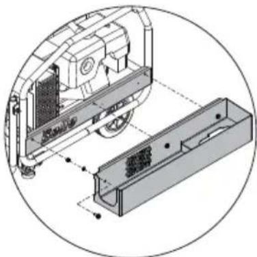
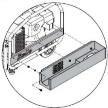
CAUTION
DO NOT lift the Power Pack with the Breaker and/or Breaker Steel still stored in the Tool Tray.

CAUTION
DO NOT leave the Breaker Steel fitted inside the Breaker whilst stored in the Tool Tray
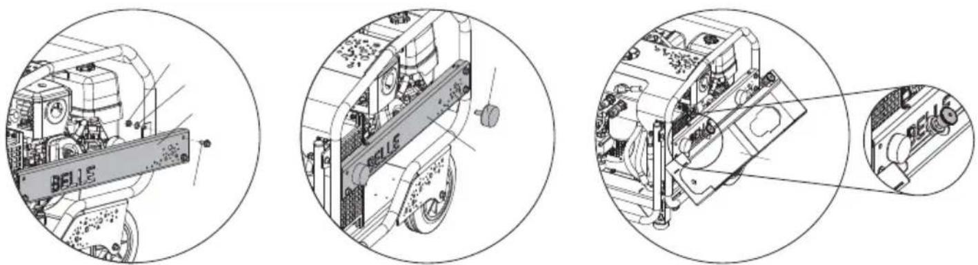
Image 1 Image 2 Image 3
Tool Tray Installation - Bulldog
- Remove left-hand side guard and 4 x M8 bolts, nuts & washers (See Image 1)
- Replace with new side guard and 4 x M8 bolts, nuts & washers provided in the kit. Tighten to 28Nm.
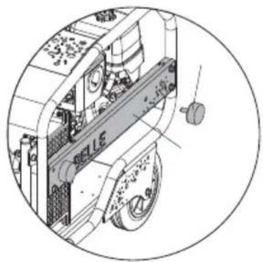
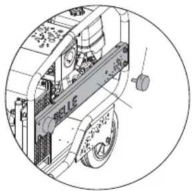
- Screw 2 x anti-vibration mounts using 2 x M10 washers and nuts provided through location holes in the new side guard, hand tightened (See Image 2)
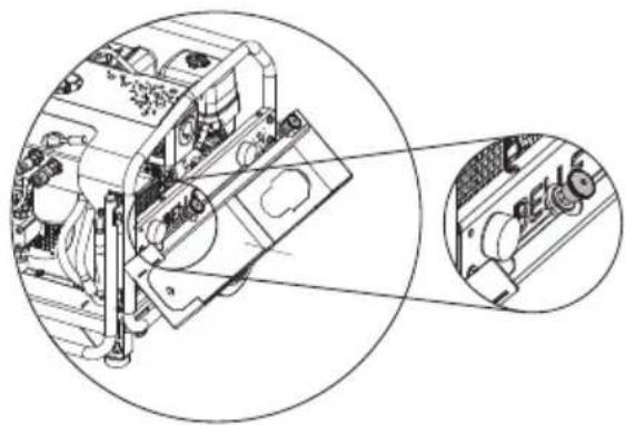
- Hook the tool tray flange underneath the installed side guard and retract both plungers (See Image 3)
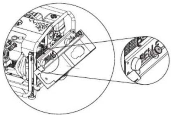
- Pivot the tool tray upwards until both plungers are located above the slots in the top of the installed side guard. Release the plunger handles to lock the assembly in place. (See Image 4)
- Ensure plungers are fully extended in the side guard slots and all bolts / nuts are correctly tightened before storing equipment in the tool tray.
natural_image
Technical line drawing of a vehicle engine bay with labeled components (no readable text or symbols)Image 4
Tool Tray Removal - Bulldog
- Ensuring there is no equipment still stored in the tool tray, retract both plungers and tilt backwards and down to un-hook the flange from the underside of the side guard.
Tool Tray Installation - HPP Range
- Line up the 3 x holes on the side of the tool tray with the 3 x holes on the left-hand side guard. Secure the tool tray to the frame using the 3 x M8 bolts, nuts & washers provided in the kit. Tighten to 28Nm (See Image 5)
Tool Tray Removal - HPP Range
- Ensuring there is no equipment still stored in the tool tray, remove the 3 x M8 bolts, nuts & washers.

natural_image
Technical diagram of a mechanical assembly with labeled components, showing a motor and housing (no text or symbols present)Image 5
Your new Altrad Belle Hydraulic Power Pack is warranted to the original purchaser for a period of one-year (12 months) from the original date of purchase. Altrad Bellewarranty is against defects in design, materials an workmanship.
The following are not covered under the Altrad Belle warranty:
- Damage caused by abuse, misuse, dropping or other similar damage caused by or as a result of failure to follow assembly, operation or user maintenance instructions.
- Alterations, additions or repairs carried out by persons other than Altrad Belleor their recognised agents.
- Transportation or shipment costs to and from Altrad Belle or their recognised agents, for repair or assessment against a warranty claim, on any machine.
- Materials and/or labour costs to renew, repair or replace components due to fair wear and tear.
The following components are not covered by warranty.
- Engine air filter
- Engine spark plug
Altrad Belle and/or their recognised agents, directors, employees or insurers will not be held liable for consequential or other damages, losses or expenses in connection with or by reason of or the inability to use the machine for any purpose.
Warranty Claims
All warranty claims should firstly be directed to Altrad Belle, either by telephone, by Fax, by Email, or in writing.
For warranty claims:
Tel : +44 (0)1298 84606, Fax : +44 (0)1298 84073, Email : Warranty@belle-group.co.uk
or Write to:
Altrad Belle Warranty Department,
Sheen, No Buxton
Derbyshire
SK17 0EU
England
Warranty Registration:
In the bid for ALTRAD Belle to become greener and more eco friendly, we have now introduced online Warranty registration. To access the registration page of our website, please use the following address:-
http://www.bellegroup.com/index.php?p=warranty_registration
Alternatively, please scan the adjacent QR Code (Quick Response Code) using your smartphone to access the registration page.

This manual has been written to help you operate and service the Hydraulic Power Pack safely. This manual is intended for dealers and operators of the Hydraulic Power Pack.
Foreword
The ‘Machine Description’ section helps you to familiarise yourself with the machine's layout and controls.
The ‘General Safety’ and ‘Health and Safety’ sections explain how to use the machine to ensure your safety and the safety of the general public.
The ‘Operating Instructions’ section helps you with the setting up and use of the machine.
The ‘Trouble Shooting Guide’ helps you if you have a problem with your machine.
The 'Service & Maintenance' section is to help you with the general maintenance and servicing of your machine.
The ‘Warranty’ section details the nature of the warranty cover and claims procedure.
The ‘Declaration Of Conformity’ section shows the standards that the machine has been built to.
Directives with regard to the notations.
Text in this manual to which special attention must be paid are shown in the following way:

CAUTION
The product can be at risk. The machine or yourself can be damaged or injured if procedures are not carried out in the correct way.

WARNING
The life of the operator can be at risk.

WARNING

WARNING
Before you operate or carry out any maintenance on this machine YOU MUST READ and STUDY this manual.
KNOW how to safely use the unit's controls and what you must do for safe maintenance.
(Be sure that you know how to switch the machine off before you switch on, in case you get into difficulty.)
ALWAYS wear or use the proper safety items required for your personal protection.
If you have ANY QUESTIONS about the safe use or maintenance of this unit, ASK YOUR SUPERVISOR OR CONTACT THE Altrad Belle+44 (0)1298 84606

Contents
How to use this manual....18
Warning 18
Machine Description.... 19
Applications....19
Decals....20 - 21
Technical Data....22
General Safety 23
Health and Safety....23
Pre-Start Safety Checks....23
Operating Instructions 24
Trouble Shooting Guide 25
Service & Maintenance 26
EHTMA - Code Of Practice 27
Environment 27
Options - Tool Tray 28
Warranty 29
Declaration of Conformity 2
text_image
HPP RANGE BULLDOG- Frame
- Cowl
- Fuel Tank
- Air Filter
- Exhaust
- Oil Cooler
- Valve Block
- Transport Handle
- Pump
- Hydraulic Oil Tank
- Transport Wheels
- Handle Latch
- Lifting Eye
- Engine Protection
- Power on Demand (POD) System.
- Hydraulic Oil Sight Glass
- Hydraulic Oil Filler Cap
Applications

The Altrad Belle Bulldog Power Pack is suitable to power the following Altrad Belle hydraulic tools.
a) BHB12 26.5lb. Hand held Pick. b) BHB19USA 41.8lb. Hand held breaker. c) BHB23USA 50.7lb Hand held breaker. d) BHB25 55.1lb. Hand held breaker. e) BHB25X 55.1lb. Hand Held Breaker f) 2322-S Submersible Water Pump.
The Bulldog Power Pack can safely be connected to any tool which carries the EHTMA Category 'C' (Green Triangle). If in doubt regarding the correct and safe connection of a tool please consult Altrad Belle, or your local Agent for advice.
The Altrad Belle Midi Power Pack is suitable to power the following Altrad Belle hydraulic tools.
a) BHB12 26.5lb. Hand held Pick. b) BHB19USA 41.8lb. Hand held breaker. c) BHB23USA 50.7lb Hand held breaker. d) BHB25 55.1lb. Hand held breaker. e) BHB25X 55.1lb. Hand Held Breaker f) 2322-S Submersible Water Pump.
The Midi Power Pack can safely be connected to any tool which carries the EHTMA Category 'C' (Green Triangle). If in doubt regarding the correct and safe connection of a tool please consult Altrad Belle, or your local Agent for advice.
The Altrad Belle Major Power Pack MAJOR/20-140X & MAJOR/20-160X is suitable to power the following Altrad Belle hydraulic tools EHTMA Cat. 'C'.
a) BHB12 26.5lb. Hand held Pick. b) BHB19USA 39.7lb. Hand held breaker. c) BHB23USA 50.7lb Hand held breaker. d) BHB25 55.1lb. Hand held breaker. e) BHB25X 55.1lb. Hand Held Breaker f) 2322-S Submersible Water Pump.
The Altrad Belle Major Power Pack MAJOR/30-140 is suitable to power the following Altrad Belle hydraulic tools EHTMA Cat. 'D'.
a) BHB30USA 59.5lb. Hand held Pick. b) BHB27X 59.5lb. Hand held Pick. c) 188 Disc Cutter
The Major Power Pack can safely be connected to any other tool which carries the relevant EHTMA Category 'D' (Brown Triangle). If in doubt regarding the correct and safe connection of a tool please consult Altrad Belle or your local Agent for advice.

text_image
BELLE 1 2 3 4 5 6 7 8 9 10 1 13- Branding Decals
- Start / Stop Procedure Decal
- Safety Decal
- Noise Decal
- CE Decal
- EHTMA Decal
- Filter Condition Decal
- Filter Fitment Decal
- Oil Level Decal
- Engine On / Off Switch Decal
- Tool Tray Safety Decal
- Tool Tray Fitment Decal
- Lifting Eye Decal
1. Branding Decals
Indiates the make and model of the machine.
2. Start / Stop Procedure Decal
Gives instructions on how to Start and Stop the Bulldog Power Pack.
3. Safety Decal

Read the
Operators Manual

Wear Ear Protection

Wear Eye Protection

Wear Protective Footwear
4. Noise Decal
Indicates the Noise Level (dB(A)) of the machine.
5. CE Decal
Indicates that the machine is CE certifi ed.
6. EHTMA Decal
Indicates the EHTMA Rating, which identifies the hydraulic flow rate and working pressure of the machine
7. Filter Condition Decal
Gives servicing information for the hydraulic filter.
8. Filter Fitment Decal
Indicates how to change the hydraulic filter.
9. Oil Level Decal
Indicates the position of the hydraulic oil guage.
10. Engine On / Off Switch Decal
Indicates the position of the Engine On / Off Switch
11. Tool Tray Safety Decal
Gives safety instructions for using the tool tray correctly.
12. Tool Tray Fitment Decal
Gives instructions for fitting the tool tray to the machine correctly.
13. Lifting Eye Decal
Gives safety instructions for using the tool tray correctly.

text_image
1. Branding Decals 2. Start / Stop Procedure Decal 3. Safety Decal 4. Noise Decal 5. CE Decal 6. EHTMA Decal 7. Filter Condition Decal 8. Filter Fitment Decal 9. Oil Level Decal 10. Tool Tray Decal 11. Lifting Eye Decal1. Branding Decals
Indiates the make and model of the machine.
2. Start / Stop Procedure Decal
Gives instructions on how to Start and Stop the Bulldog Power Pack.
3. Safety Decal

Read the
Operators Manual

Wear Ear Protection

Wear Eye Protection

Wear Protective Footwear
4. Noise Decal
Indicates the Noise Level (dB(A)) of the machine.
5. CE Decal
Indicates that the machine is CE certified.
6. EHTMA Decal
Indicates the EHTMA Rating, which identifies the hydraulic flow rate and working pressure of the machine
7. Filter Condition Decal
Gives servicing information for the hydraulic filter.
8. Filter Fitment Decal
Indicates how to change the hydraulic filter.
9. Oil Level Decal
Indicates the position of the hydraulic oil guage.
10. Tool Tray Decal
Gives safety instructions for using the tool tray correctly.
11. Lifting Eye Decal
Gives safety instructions for using the tool tray correctly.
| Model | Bulldog | 20-110D* | 20-140 |
| Type | Compact | Midi | Midi |
| Engine | Honda GX270 | Lombardini 15LD 350 | Honda GX270 |
| Engine Power (Hp) | 9 | 7.5 | 9 |
| Hydraulic Flowrate (Gals/Min) | 20 | 5.3 | 5.3 |
| Working Pressure (Bar) | 140 | 110 | 140 |
| Length (in) (With Handle Folded) | 705 | 29.1 | 29.1 |
| Width (in) | 515 | 21.9 | 21.9 |
| Height (in) | 620 | 24.4 | 24.4 |
| Hydraulic Connections | 3/8" / 1/2" | 3/8" / 1/2" | 3/8" / 1/2" |
| Flat faced, quick release, Non-drip couplings | |||
| Hydraulic Oil Type | -Below 30° = ISO VG T32. - Above 30° = ISO VG T46 | ||
| Dry Weight (lbs) | 66 | 147.7 | 132.3 |
| Weight Including Oils (lbs) | 160.9 | 145.5 | |
| Oil Tank Capacity (Gals) | 5.6 | 1.68 | 1.68 |
| Fuel Type | Unleaded | Diesel | Unleaded |
| Fuel Tank Capacity (Gals) | 6 | 1.14 | 1.59 |
| Noise Level (dB(A)) | 104 | 104 101 | |
| Model 20-140X 20-160X 30-140 | |||
| Type Major Major Major | |||
| Engine Honda GX390 Honda GX390 Honda GX390 | |||
| Engine Power (Hp) 13 13 13 | |||
| Hydraulic Flowrate (Gals/Min) 5.3 5.3 7.9 | |||
| Working Pressure (Bar) | 140 | 160 | 140 |
| Length (in) (With Handle Folded) | 29.1 29.1 29.1 | ||
| Width (in) | 21.9 21.9 21.9 | ||
| Height (in) | 24.4 24.4 24.4 | ||
| Hydraulic Connections | 3/8" / 1/2" | 3/8" / 1/2" 3/8" / 1/2" | |
| Flat faced, quick release, Non-drip couplings | |||
| Hydraulic Oil Type | -Below 30° = ISO VG T32. - Above 30° = ISO VG T46 | ||
| Dry Weight (lbs) | 158.7 158.7 | 158.7 | |
| Weight Including Oils (lbs) | 172.0 172.0 | 172.0 | |
| Oil Tank Capacity (Gals) | 1.64 | 1.64 | 1.72 |
| Fuel Type | Unleaded | Unleaded | Unleaded |
| Fuel Tank Capacity (Gals) | 1.72 | 1.72 | 1.72 |
| Noise Level (dB(A)) | 101 | 101 101 | |
* = Not CE Approved
General Safety

The following precautions should be taken before operating Altrad Belle Hydraulic Power Units and Road Breaking Tools.
a) Read this Operators Guide and the operating handbook for the tool to be connected and run. Observe the manufacturers recommendations.
b) Never operate the power units and tools without the correct Personal Protection Equipment. Altrad Belle recommend the use of protective goggles and/or face shield, ear defenders, protective footwear, gloves, and hand hat.
c) Ensure that the 'STEEL' is securely locked into the breaker.
d) Only operate the Power unit in a well Ventilated area ensuring adequate flow of air for the cooling fan and the removal of the exhaust gases.
e) Ensure that a safe operating work position (Workstation) is selected. Altrad Belle recommend that tools are operated at the extremity of the transmission hoses connecting the tool to the power unit.
f) Ensure that the hydraulic tool is compatible with the hydraulic power supply to be used. It is DANGEROUS to use a hydraulic tool with an incompatible flow rate and pressure.
NOTE:- Hydraulic power units and tools supplied by EHTMA member companies carry range identification labels and it is essential to check that the tools and power unit have the same identification label.
g) Check the power unit, hoses and tools frequently for damage and/or leaks.
h) Do not adjust the power pack settings, ie:- the engine speed/flow rate, Relief Valve pressure setting etc. Operating with flows and pressures outside the specifications can be dangerous.
j) All loose items (Hoses, Hydraulic Breaker, Steel) should be removed before lifting as they are not secured and may cause a falling object hazard when lifting.
k) Use only Altrad Belle replacement parts. It can Prove dangerous to fit obscure parts.

WARNING
Never attempt to add fuel or oil when the engine is running. Use only the correct grade, and do not overfi ll.
Health and Safety

Vibration
Some vibration from the machines operation is transmitted through the handle to the operator's hands. The Altrad BelleHydraulic Tool range has been specifically designed to reduce hand/arm vibration levels. Refer to specifications & technical data for vibration levels and usage times (recommended maximum daily exposure time). DO NOT exceed the maximum usage times.
PPE (Personal Protective Equipment)
Personal injury or property damage may be caused by knocks, crushing, slipping, tripping, falling, or by flying chips due mainly to the improper or careless handling of the machine, or working in a confined area.
Suitable PPE must be worn when using this equipment i.e. Safety Goggles, Gloves, Ear Defenders, Dust Mask and Steel Toe capped footwear. Wear clothing suitable for the work you are doing. Tie back long hair and remove any jewellery which may catch in the equipment's moving parts.
Dust
Many of the tools which can be used with this Power Pack can produce dust, which may be hazardous to your health. Always wear a mask that is suited to the type of dust being produced.
Pre-start Checks

1) Ensure that the Power Unit is standing on stable ground or where necessary that it is suitable checked for stability.

CAUTION
Do not operate the machine at an angle of greater than 20 degrees, otherwise the engine lubricating system may fail, causing extensive damage to the engine.
2) Ensure that the engine exhaust is not obstructed and that there is adequate ventilation to disperse the exhaust gases.
3) Ensure that the transmission hoses are positioned to avoid damage by vehicles etc., and that they will not be understrain when the accessory tool is in use.

CAUTION
Ensure that the hose couplings to the accessory tool are thoroughly cleaned before ceconnecting. Failure to do so may cause damage to the seals.
4) Check engine fuel and oil level, and top up as necessary. Refer to the engine manuals for details of grade.
5) Check hydraulic oil level and top up as necessary.
NOTE:- When topping up the hydraulic tank it is advisable to use a strainer. Do not overfill.
Take the Power Pack to where it is required.
When using the wheels and transport handle ALWAYS ensure the handle latch is engaged before transporting the Power Pack (see image)
Where it is necessary to use lifting equipment to position the Power Pack, make sure the lifting equipment has a WLL (Working Load Limit) suitable for the Power Pack's weight (see Technical Data section or machine serial plate). Attach suitable chains or slings ONLY to the lifting point on the top of the Power Pack.
Starting the Engine
NOTE:- Refer to the engine manual for details. Always ensure the Bypass lever is in the Bypass position.
natural_image
Mechanical diagram showing a rotating device with a curved arm and pulley (no text or symbols)Petrol Engines
1) Open the fuel tap.
2) Close the choke on the carburetter.
3) Set the engine ignition switch to 'ON'.
4) Start the Engine by pulling on the recoil starter rope.
5) As the engine warms up, gradually return the choke to 'OPEN'.
NOTE:- Midi and Major petrol Power Packs are fitted with a Power On Demand device and the engine will run at idle speed until pressure is generated in the hydraulic system.
Diesel Engines
1) Open the fuel tap.
2) Set the engine speed control to the 'START' position.
3) Set the decompressor lever to the 'START' position.
4) Start the engine by pulling the recoil starter rope.
Operating Checks
Before commencing operation with the accessory tool connected, the following checks should be carried out.
1) Bypass lever is in the "FLOW" position.
2) Check that there is no excessive engine vibrations.
3) Ensure that there are no hydraulic leaks from hoses or couplings.
4) Check that the filter condition indicator is not within the clogging sector. When this sector is indicated, the return line filter should be replaced.
Depending on the ambient temperature, optimum performance is usually achieved after 5-10 minutes operation, this is the time required for the hydraulic oil to reach its correct operating temperature.
Stopping the Engine
NOTE:- Refer to the engine manual for details.
Petrol Engines.
1) Set the bypass lever to the 'BYPASS' position.
2) Set the ignition switch to 'OFF'.
3) Switch off the fuel tap.
Diesel Engines.
1) Set the bypass lever to the 'BYPASS' position.
2) Set the engine speed control to the 'STOP' position.
3) Switch off the fuel tap.
Troubleshooting Guide
| Problem Cause Remedy | ||
| Engine stops or will not start. | Fuel tap switched off. Switch on fuel tap. | |
| Fuel shortage. Refuel. | ||
| Fuel line blocked. Clean fi Iters/pipes. | ||
| Air vents in fi Iter cap blocked. Clean. | ||
| Air cleaner blocked. Clean or renew element. | Refer to engine manual. | |
| Engine malfunctions. Refer to engine manual. | ||
| Low engine oil (Gasoline only). | Top up to correct level. Refer to engine manual for correct grade. | |
| Insuffi cient oil in hydraulic tank (Gasoline only). | Top up to correct level (Refer to Technical Data Section) | |
| Engine Ignition switch or connecting wires damaged (Gasoline units only). | Check for earth leak, and renew worn or damaged parts. | |
| Hydraulic tank fl oat switch wires damaged (Gasoline units only). | Renew worn or damaged parts. | |
| Hydraulic pump seized. Renew pump. | ||
| Hydraulic Oil Pressure low. | Bypass lever is in the ‘BYPASS’ position. Set to ‘FLOW’. | |
| Relief valve set low or worn. Check relief valve setting and adjust. | ||
| Pump worn or damaged. | Check system oil flow. Renew pump as necessary. | |
| Engine power low. | Refer to engine manual. | |
| Accessory Tool running hot or loose. | Radiator fins blocked. | Clean using air blast. |
| Oil cooler fan damaged. | Tighten or renew as necessary | |
| Hydraulic pump worn or damaged. | Renew pump. | |
| Relief valve set low or worn. Check setting and renew as necessary. | ||
| Hydraulic oil contaminated. | Drain oil tank and transmission hoses and replenish with clean oil. Replace fi Iters. | |
| Engine speed remains at idle when tools are operated (if fitted) | P.O.D. Cylinder seized in retracted position. | Check the cylinder and replace as necessary |
| Throttle lever incorrectly set at low speed. | Reset engine speed and lock throttle lever. | |
| Engine speed remains at full when off load / Bypass. | P.O.D. Cylinder seized in extended position. | Check cylinder and replace as necessary. |
| P.O.D. Cable adjustment incorrect. | Re-adjust as necessary. | |
The following schedule details the attentions considered necessary to ensure satisfactory operation of the power unit.
NOTE:- The attentions and periods summarised in the schedule are the initial recommendations and should be revised to suit the Power Unit working conditions.
| Item Attention | First 50 Hours | 10 Hours | 100 Hours | 300 Hours | |
| Complete Unit. | Keep all areas clean and free from dust, debris etc. | √ | |||
| Check security of all fasteners especially on engine mountings. | √ | ||||
| Wheels and Feet. Examine for damage. | √ | ||||
| Transmission Hoses. | Examine for leaks or damage. | √ | |||
| Check for the correct positioning of the protective sleeves. | √ | ||||
| Engine. | Check oil level. | √ | |||
| Examine mountings. | √ | ||||
| Examine exhaust silencer for damage of deterioration. | √ | ||||
| Check for excess vibration when running. | √ | ||||
| Change Oil/Service (Refer to manufacturers instructions). | |||||
| Hydraulic Tank. | Check oil level. | √ | |||
| Replace Filter. | √ | √ | |||
| Change Hydraulic Oil. | √ | ||||
| Oil Cooler. | Externally clean using compressed air.DO NOT USE A WIRE BRUSH | √ | |||
| Return Line Filter. | Replace filter | √ | |||
| Hydraulic pipes / connectors. | Examine for oil leaks. | √ | |||
System Pressure and Flow Checks
- Connect a suitable hydraulic test unit to the powerpack. The unit should comprise a high pressure flowmeter 0-50l/min, a gauge 0-200 bar (0-3000psi), a temperature gauge, and a load valve. Suggested unit available from UCC (UC4120).
- Connect the test unit to the power pack with the load valve and the By-Pass lever in the by-pass position and start the power pack. Allow the engine to warm up, set the by-pass lever to the flow position. Close the load valve completely and check that the relief valve setting is correct. The hydraulic oil will tend to get quite hot during this operation and therefore the checking should be carried out as quickly as possible and the load valve opened before excessive temperatures are reached.
- Carefully close the load valve to raise the pressure to 100 Bar. Check that the flow rate is between 18 and 20 l/min (28 and 30 l/min for Major 30-140). Adjust the engine speed to give the correct flow. DO NOT EXCEED 3600 RPM (2900 RPM for Major 30-140) "on load". If correct flow cannot be obtained within max engine speed then the pump must be replaced
EUROPEAN HYDRAULIC TOOL MANUFACTURERS ASSOCIATION CODE OF PRACTICE – HYDRAULIC POWER SYSTEMS
Before Starting. Refer to manufacturer's operating instructions.
Compatibility. Hydraulic Power Systems are designed to operate at a specific Flow and Pressure. Equipment produced by EHTMA members carries a triangular colour coded range identification label. Check that both the tool and power unit have the same identification label before operation. It is imperative that power systems and tools having different colour codings are not interconnected as this practice is both inefficient and dangerous.
For reference the EHTMA colour code is as follows:-
| Classifi cation Colour | Code. Flow 1/min Max pressure | Bar. | |
| A Yellow 5.5 – 6.5 | 180 | ||
| B Blue | 13.5 – 16.5 | 172 | |
| C | Green | 18.0 – 22.0 | 138 |
| D Brown | 27.0 – 33.0 | 138 | |
| E | Red 36.0 – 44.0 | 138 | |
| F | Black | 45.0 – 55.0 | 138 |
| G | Orange | 54.0 – 66.0 | 138 |
| Z Grey | 9.0 – 11.0 | 180 |
If in doubt consult the equipment manufacturer.
Characteristics. Operators not familiar with the use of hydraulic tools should note the following points:-
1) Hydraulic breakers are usually more powerful than the equivalent weight pneumatic tools.
2) The body of the hydraulic breaker and the supply hoses will become quite warm during normal operation.
3) As the breaker has no exhaust it is generally much quieter in operation. This should not be taken as a lack of power.
Safety Points.
1) Always wear safety footwear when operating breaking equipment.
2) Eye protection is strongly recommended, particularly on hard surfaces.
3) Ensure that the 'steel' is securely locked into the breaker.
4) Check hoses for deep cuts or exposed braiding; replace any damaged hose.
Environment

Safe Disposal.

Instructions for the protection of the environment. The machine contains valuable materials. Take the discarded apparatus and accessories to the relevant recycling facilities.
| Component | Material |
| Handle | Steel |
| Chassis | Steel |
| Frame Steel | |
| Engine | Steel, Aluminium & Plastic |
| Hydraulic Oil Tank | Steel |
| Hydraulic Pump | Steel & Aluminium |
| Hoses | Steel & Rubber |
| Valve Block | Aluminium |
| Flexible Mounts | Steel & Rubber |
| Various Parts | Steel & Aluminium |

CAUTION
DO NOT lift the Power Pack with the Breaker and/or Breaker Steel still stored in the Tool Tray.

CAUTION
DO NOT leave the Breaker Steel fitted inside the Breaker whilst stored in the Tool Tray

Image 1 Image 2 Image 3
Tool Tray Installation - Bulldog
- Remove left-hand side guard and 4 x M8 bolts, nuts & washers (See Image 1)
- Replace with new side guard and 4 x M8 bolts, nuts & washers provided in the kit. Tighten to 28Nm.
- Screw 2 x anti-vibration mounts using 2 x M10 washers and nuts provided through location holes in the new side guard, hand tightened (See Image 2)
- Hook the tool tray flange underneath the installed side guard and retract both plungers (See Image 3)
- Pivot the tool tray upwards until both plungers are located above the slots in the top of the installed side guard. Release the plunger handles to lock the assembly in place. (See Image 4)
- Ensure plungers are fully extended in the side guard slots and all bolts / nuts are correctly tightened before storing equipment in the tool tray.
natural_image
Technical line drawing of a vehicle engine bay with labeled components (no readable text or symbols)Image 4
Tool Tray Removal - Bulldog
- Ensuring there is no equipment still stored in the tool tray, retract both plungers and tilt backwards and down to un-hook the flange from the underside of the side guard.
Tool Tray Installation - HPP Range
- Line up the 3 x holes on the side of the tool tray with the 3 x holes on the left-hand side guard. Secure the tool tray to the frame using the 3 x M8 bolts, nuts & washers provided in the kit. Tighten to 28Nm (See Image 5)
Tool Tray Removal - HPP Range
- Ensuring there is no equipment still stored in the tool tray, remove the 3 x M8 bolts, nuts & washers.
natural_image
Technical line drawing of a mechanical assembly with no visible text or symbolsImage 5
Your new Altrad Belle Hydraulic Power Pack is warranted to the original purchaser for a period of one-year (12 months) from the original date of purchase. Altrad Bellewarranty is against defects in design, materials an workmanship.
The following are not covered under the Altrad Belle warranty:
- Damage caused by abuse, misuse, dropping or other similar damage caused by or as a result of failure to follow assembly, operation or user maintenance instructions.
- Alterations, additions or repairs carried out by persons other than Altrad Belleor their recognised agents.
- Transportation or shipment costs to and from Altrad Belle or their recognised agents, for repair or assessment against a warranty claim, on any machine.
- Materials and/or labour costs to renew, repair or replace components due to fair wear and tear.
The following components are not covered by warranty.
- Engine air filter
- Engine spark plug
Altrad Belle and/or their recognised agents, directors, employees or insurers will not be held liable for consequential or other damages, losses or expenses in connection with or by reason of or the inability to use the machine for any purpose.
Warranty Claims
All warranty claims should firstly be directed to Altrad Belle, either by telephone, by Fax, by Email, or in writing.
For warranty claims:
Tel : +1.540.345.5090, Fax : +1 540 345 5091 Email : sales@Altrad Bellegroup.net
or Write to:
Altrad BelleInc
3959 Electric Rd, Suite 360, Roanoke, VA, 24018, USA.
Warranty Registration:
In the bid for ALTRAD Belle to become greener and more eco friendly, we have now introduced online Warranty registration. To access the registration page of our website, please use the following address:-
http://www.bellegroup.com/index.php?p=warranty_registration
Alternatively, please scan the adjacent QR Code (Quick Response Code) using your smartphone to access the registration page.

text_image
Technical diagram of a device casing with numbered components labeled 1, 6, 7, and 10natural_image
Mechanical diagram showing a rotating device with a curved arrow indicating motion (no text or symbols)Moteurs à essence
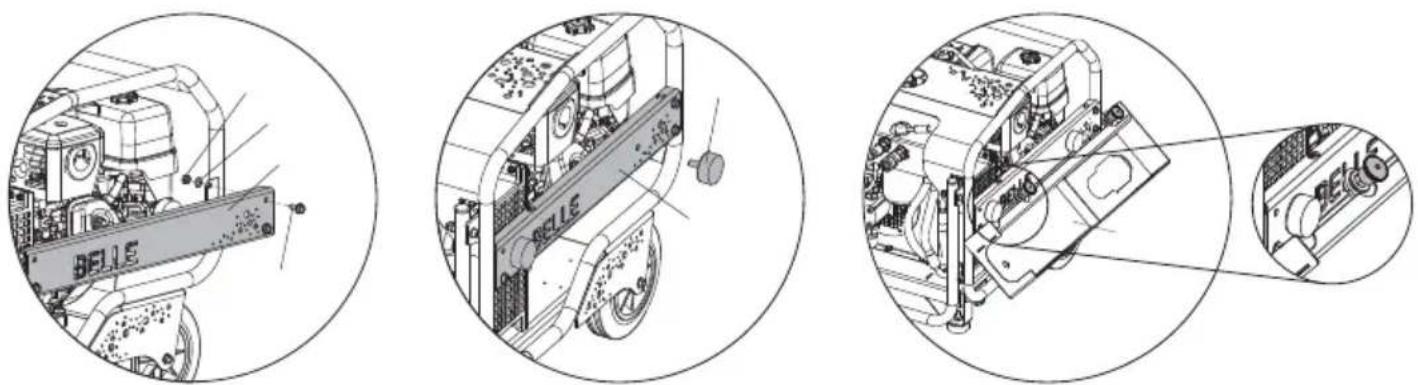
Image 1 Image 2 Image 3
natural_image
Technical line drawing of a vehicle engine bay with labeled components (no readable text or symbols)Image 4
natural_image
Technical diagram of a mechanical assembly with labeled components, showing internal components and alignment lines (no readable text or symbols)Image 5
Altrad Belle Warranty Department,
Sheen, No Buxton
Derbyshire
SK17 0EU
England
natural_image
Mechanical diagram showing a rotating device with a curved arrow indicating motion (no text or symbols)Motores a gasolina
natural_image
Technical line drawing of a vehicle chassis with labeled components (no readable text or symbols)Imagen 4
natural_image
Technical diagram of a mechanical assembly with labeled components, showing internal components and alignment lines (no readable text or symbols)Imagen 5
Altrad Belle Warranty Department,
Sheen, No Buxton
Derbyshire
SK17 0EU
Inglaterra
Registro de Garantia :
http://www.bellegroup.com/index.php?p=warranty\_registration
natural_image
Mechanical diagram showing a rotating device with a curved arrow indicating motion (no text or symbols)Ligar o motor da central hidráulica Altrad Belle
| Classifi cação Código de Cor Caudal I/min Pressão Máxima Bar | |||
| A Amarelo | 5,5 – 6,5 180 | ||
| B | Azul | 13,5 – 16,5 | 172 |
| C | Verde | 18,0 – 22,0 | 138 |
| D | Castanho | 27,0 – 33,0 | 138 |
| E | Encarnado | 36,0 – 44,0 | 138 |
| F | Preto | 45,0 – 55,0 | 138 |
| G | Laranja | 54,0 – 66,0 | 138 |
| Z Cinzento | 9,0 – 11,0 | 180 | |
natural_image
Technical line drawing of a mechanical assembly with labeled parts (no readable text or symbols)Imagem 4
natural_image
Technical diagram of a mechanical assembly with a wheel and housing (no visible text or symbols)Imagem 5
text_image
QR code image containing encoded data, no visible human-readable textnatural_image
Mechanical diagram showing a rotating device with a curved arrow indicating motion (no text or symbols)De Motor Starten.
natural_image
Technical line drawing of a mechanical device with no visible text or symbolsAfbeelding 1
natural_image
Technical diagram of a mechanical assembly with labeled parts, showing internal components and motion indicators (no readable text or symbols)Afbeelding 2
natural_image
Technical line drawing of an electronic device with internal components and a magnified inset showing a close-up view (no text or symbols)Afbeelding 3
Installatie Gereedschapslade - Bulldog
natural_image
Technical line drawing of a mechanical device with labeled parts, no readable text or symbols presentAfbeelding 4
natural_image
Technical diagram of a mechanical assembly with labeled components, showing internal components and alignment lines (no readable text or symbols)Afbeelding 5
Altrad Belle Warranty Department,
Sheen, Nr. Buxton
Derbyshire
SK17 0EU
England
text_image
QR code image containing encoded data, no visible human-readable textnatural_image
Mechanical diagram showing a rotating device with a curved arrow indicating rotation (no text or symbols)Opstart af motoren
| Klassifikation | Farvekode | Gennemstrømning 1/min | Maksimalt tryk Bar. |
| A Gul 5,5 – 6,5 | 80 | ||
| B | Blå | 13,5 – 16,5 | 172 |
| C | Grøn | 18,0 – 22,0 | 138 |
| D | Brun | 27,0 – 33,0 | 138 |
| E | Rød | 36,0 – 44,0 | 138 |
| F | Sort | 45,0 – 55,0 | 138 |
| G Orange | 54,0 – 66,0 | 138 | |
| Z Grå | 9,0 – 11,0 | 180 |
Instructions for the protection of the environment. The machine contains valuable materials. Take the discarded apparatus and accessories to the relevant recycling facilities.
| Komponent | Materiale |
| Håndtag | Stål |
| Chassis | Stål |
| Hovedstel | Stål |
| Motor | Stål, Aluminium & Plast |
| Hydraulikoliebeholder | Stål |
| Hydraulikpumpe | Stål & Aluminium |
| Slanger | Stål & Gummi |
| Ventilblok | Aluminium |
| Fleksible dæmpninger | Stål & Gummi |
| Forskeliige Dele Stål & | Aluminium |

FORSIGTIG
natural_image
Technical line drawing of a mechanical assembly with labeled parts (no readable text or symbols)Billede 4
natural_image
Technical diagram of a mechanical assembly with a wheel and housing (no visible text or symbols)Billede 5
ALTRAD Belle Warranty Department,
Sheen, No Buxton
Derbyshire
SK17 0EU
England
Garantiregistrering:
text_image
QR code image containing encoded data, no visible human-readable textnatural_image
Mechanical diagram showing a rotating device with a curved arrow indicating motion (no text or symbols)Anlassen des motors
natural_image
Technical line drawing of a mechanical assembly with labeled parts (no readable text or symbols)Abb. 4
natural_image
Technical diagram of a mechanical assembly with a circular cross-section view showing internal components (no text or labels)Abb. 5
Gewährleistung
Altrad Belle Warranty Department,
Sheen, No Buxton
Derbyshire
SK17 0EU
England
text_image
QR code image containing encoded data, no visible human-readable textI
How To Use This Manual
natural_image
Mechanical device diagram showing a rotating arm mechanism with no visible text or symbolsMotori a benzina.
| Classificazione | Codice di Colore | Flusso l/min | Bar di Pressione Massima |
| A Giallo 5,5 - 6,5 | 180 | ||
| B Blu 13,5 - 16,5 | 172 | ||
| C Verde | 18,0 - 22,0 | 138 | |
| D | Marrone | 27,0 - 33,0 | 138 |
| E | Rosso | 36,0 - 44,0 | 138 |
| F | Nero | 45,0 - 55,0 | 138 |
| G | Arancione | 54,0 - 66,0 | 138 |
| Z Grigio | 9,0 - 11,0 | 180 |
natural_image
Technical illustration of a mechanical assembly with labeled components (no readable text or symbols)Immagine 4
natural_image
Technical line drawing of a mechanical assembly with no visible text or symbolsImmagine 5
ALTRAD Belle Warranty Department,
Sheen, No Buxton
Derbyshire
SK17 0EU
England
http://www.bellegroup.com/index.php?p=warranty\_registration
text_image
QR code image containing encoded data, no visible human-readable text
natural_image
Mechanical diagram showing a rotating device with a curved arrow indicating motion (no text or symbols)Bensinmotorer.
natural_image
Technical line drawing of a mechanical assembly with labeled parts (no readable text or symbols)Bild 4
natural_image
Technical diagram of a mechanical assembly with no visible text or symbolsBild 5
Altrad Belle Warranty Department,
Sheen, No Buxton
Derbyshire
SK17 0EU
England
Garantiregistrering:
text_image
QR code image containing encoded data, no visible human-readable text
Wear Protective Footwear
4. Melutarra

Wear Protective Footwear
4. Melutarra
natural_image
Mechanical diagram showing a rotating device with a curved arrow indicating motion (no text or symbols)natural_image
Technical line drawing of a mechanical assembly with labeled parts, no readable text or symbols present.Kuva 4
Työkalulokeron irrotus - Bulldog
natural_image
Technical illustration of a mechanical assembly with no visible text or symbolsKuva 5
Altrad Belle Warranty Department,
Sheen, No Buxton
Derbyshire
SK17 0EU
England
text_image
QR code image containing encoded data, no visible human-readable textnatural_image
Mechanical diagram showing a rotating device with a curved arrow indicating motion (no text or symbols)natural_image
Technical line drawing of an internal combustion engine component (no text or symbols visible)Rys. 4
natural_image
Technical diagram of a mechanical assembly with no visible text or symbolsRys. 5
Altrad Belle Warranty Department
Sheen, Nr. Buxton,
Derbyshire,
SK17 0EU
England.
text_image
QR code image containing encoded data, no visible human-readable textnatural_image
Mechanical diagram showing a rotating device with a curved arrow indicating motion (no text or symbols)Запуск Мотора
natural_image
Technical illustration of an electronic device with labeled components, enclosed in a circular frame (no readable text or symbols)puc. 4
natural_image
Technical diagram of a mechanical assembly with no visible text or symbolspuc. 5
Altrad Belle Warranty Department
Sheen, Nr. Buxton
Derbyshire
SK17 0EU
England
text_image
QR code image containing encoded data, no visible human-readable textEHTMA – Praktilised Juhised....171
Keskkond....171
Indiates the make and model of the machine.
2. Start / Stop Procedure Decal
Gives instructions on how to Start and Stop the Bulldog Power Pack.
3. Safety Decal

Lugege
kasutusjuhendit
natural_image
Mechanical diagram showing a rotating device with a curved arrow indicating motion (no text or symbols)natural_image
Technical diagram of a mechanical assembly with labeled parts, showing internal components and no readable text or symbols.Imagen 4
natural_image
Technical diagram of a mechanical assembly with no visible text or symbolsImagen 5
Altrad Belle Warranty Department,
Sheen, Nr. Buxton
Derbyshire
SK17 0EU
England
Garantii Registreerimine
text_image
QR code image containing encoded data, no visible human-readable textnatural_image
Mechanical diagram showing a rotating device with a curved arrow indicating motion (no text or symbols)Motora leslēgšana
natural_image
Technical line drawing of a mechanical device with labeled components (no readable text or symbols)attēlu 1
natural_image
Technical diagram of a mechanical assembly with labeled parts, showing internal components and motion indicators (no readable text or symbols)attēlu 2
natural_image
Technical line drawing of a mechanical assembly with an inset close-up view (no text or symbols)attēlu 3
natural_image
Technical line drawing of a mechanical assembly with labeled parts, no readable text or symbols present.attēlu 4
natural_image
Technical diagram of a mechanical assembly with a wheel and housing (no visible text or symbols)attēlu 5
E-pasts: Warranty@belle-group.co.uk
Rakstiski
Altrad Belle Warranty Department,
Sheen, Nr. Buxton
Derbyshire
SK17 0EU
England
http://www.bellegroup.com/index.php?p=warranty\_registration
text_image
QR code image containing encoded data, no visible human-readable texttext_image
Technical diagram of a device casing with numbered components and internal structure annotationsnatural_image
Mechanical diagram showing a rotating device with a curved arrow indicating motion (no text or symbols)Benzininis variklis.
natural_image
Technical line drawing of a mechanical device with no visible text or symbols
natural_image
Technical diagram of a mechanical assembly with labeled parts, showing internal components and motion indicators (no readable text or symbols)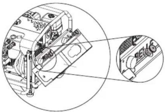
natural_image
Technical line drawing of an electronic device showing internal components and a close-up view (no text or symbols)Pav. 1 Pav. 2 Pav. 3
Irankio déklo montavimas - Bulldog
natural_image
Technical line drawing of a mechanical assembly with labeled parts (no readable text or symbols)Pav. 4
Jrankio déklo išémimas - Bulldog
natural_image
Technical diagram of a mechanical assembly with no visible text or symbolsPav. 5
el. paštas: Warranty@belle-group.co.uk
Rašykite:
Altrad Belle Warranty Department,
Sheen, Nr. Buxton
Derbyshire
SK17 0EU
England.
text_image
QR code image containing encoded data, no visible human-readable textnatural_image
Mechanical diagram showing a rotating device with a curved handle and wheel (no text or symbols)Запалване На Мотора
natural_image
Technical line drawing of a mechanical assembly with labeled parts (no readable text or symbols)фигура 4
natural_image
Technical diagram of a mechanical assembly with no visible text or symbolsфигура 5
Altrad Belle Warranty Department,
Sheen, Nr. Buxton,
Derbyshire,
SK17 0EU
England.
text_image
QR code image containing encoded data, no visible human-readable textnatural_image
Mechanical diagram showing a rotating device with a curved arrow indicating motion (no text or symbols)Startování motoru
natural_image
Technical line drawing of an engine compartment with visible gears and housing (no text or symbols)Obr. 4
natural_image
Technical diagram of a mechanical assembly with a circular cross-section view showing internal components (no text or labels)Obr. 5
Altrad Belle Warranty Department,
Sheen, Nr. Buxton,
Derbyshire,
SK17 0EU
England
Registrace Záruky:
text_image
QR code image containing encoded data, no visible human-readable textnatural_image
Mechanical diagram showing a rotating device with a curved arrow indicating motion (no text or symbols)Pornirea motorului
| Clasificare | Codul de culoare | Debit 1/ min | Presiune maximă – bar |
| A Galben 5,5 – | 6,5 180 | ||
| B Albastru 13,5 – | 16,5 172 | ||
| C | Verde | 18,0 – 22,0 138 | |
| D | Maro | 27,0 – 33,0 | 138 |
| E | Roșu | 36,0 – 44,0 | 138 |
| F | Negru 45,0 – 55,0 | 138 | |
| G | Portocaliu | 54,0 – 66,0 | 138 |
| Z | Gri | 9,0 – 11,0 180 |
natural_image
Technical line drawing of a mechanical assembly with labeled parts, no readable text or symbols present.Imaginea 4
Demontarea tăvii de scule - Bulldog
natural_image
Technical line drawing of a mechanical assembly with no visible text or symbolsImaginea 5
Altrad Belle Warranty Department,
Sheen, Nr. Buxton
Derbyshire
SK17 0EU
England.
http://www.bellegroup.com/index.php?p=warranty\_registration
text_image
QR code image containing encoded data, no visible human-readable textnatural_image
Mechanical diagram showing a rotating device with a curved arrow indicating motion (no text or symbols)A Motor Indítása
natural_image
Technical line drawing of a mechanical device with no visible text or symbolsKép 1 Kép 2 Kép 3
natural_image
Technical line drawing of a mechanical device with labeled parts (no readable text or symbols)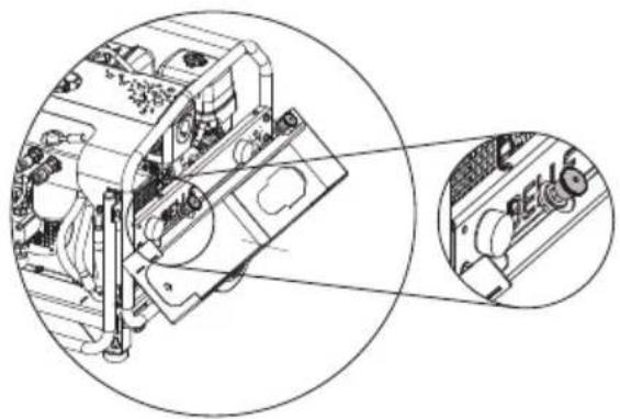
natural_image
Technical line drawing of a mechanical assembly with circular annotations highlighting internal components (no text or symbols)natural_image
Technical line drawing of an internal combustion engine component (no text or symbols visible)Kép 4
natural_image
Technical diagram of a mechanical assembly with no visible text or symbolsKép 5
Altrad Belle Warranty Department,
Sheen, Nr. Buxton
Derbyshire
SK17 0EU
England.
text_image
QR code image containing encoded data, no visible human-readable textOva uputstva su napisana kao pomoć za sigurno rukovanje i servisiranje hidrauličkog agregata. Ova uputstva su namjenjena prodavačima i rukovateljima hidrauličkog agregata.
Predgovor
Do not operate the machine at an angle of greater than 20 degrees, otherwise the engine lubricating system may fail, causing extensive damage to the engine.
2) Osigurajte da ispuh motora nije začepljen i da se prostor dovoljno prozračuje da bi se ispušni plinovi raspršili.
3) Osigurajte da su hidrauličke cijevi postavljene tako da se izbjegava oštečivanje prelaskom vozila itd., te da nisu pre nategnute kad je priljučni alat u uporabi.

PAŽNJA
natural_image
Mechanical diagram showing a rotating device with a curved arrow indicating motion (no text or symbols)Startanje motora
natural_image
Technical line drawing of a mechanical assembly with labeled parts (no readable text or symbols)Sl. 4
natural_image
Technical diagram of a mechanical assembly with no visible text or symbolsSl. 5
Vaša nova Altrad Belle Hidraulična pogonska jedinica ima garanciju prema krajnjem naručitelju za period od jedne godine (12 mjeseci) od pravog datuma isporuke.
Altrad Belle garancija odnosi se na pogreške u dizajnu, ugrađenom materijalu, i sastavljanju stroja.
Altrad Belle Warranty Department,
Sheen, Nr. Buxton,
Derbyshire,
SK17 0EU
England.
Registracija Jamstva:
U nastojanju da ALTRAD Belle postane zeleniji i ekološki osvješteniji, uveli smo registraciju jamstva putem interenta. Kako biste pristupili našoj internetskoj stranici za registraciju, koristite sljedeću poveznicu:
http://www.bellegroup.com/index.php?p=warranty_registration.
text_image
QR code image containing encoded data, no visible human-readable textBULLDOG
text_image
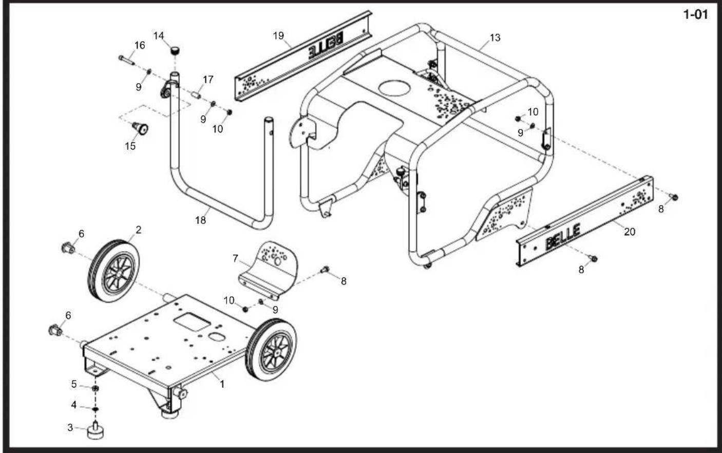
1-01 16 14 9 17 9 10 15 19 13 10 9 18 20 8 6 2 7 8 10 9 BELLE 6 5 4 3 1Chassis Assembly, Ensemble Châssis, Conjunto de Chasis, Conjunto do Chassis
| 1 | 02500 | Chassis | Chássis | Chasis | Chassis | 1 |
| 2 | 60/0285 | Wheel | Roue | Rueda | Roda | 2 |
| 3 | 00525-B | Feet | Pieds | Patas | Pés | 2 |
| 4 | 4/1003 | Washer | Rondelle | Arandela | Anilha | M10 |
| 5 | 8/10003 | Nut | Ecrou | Tuerca | Porca | M10 |
| 6 | 02515 | Boss | Bossage | Resalto | Ressalto | 4 |
| 7 | 02512 | Guard | Carène | Defensa | Guarda | 1 |
| 8 | 7/8037 | Screw | Vis | Tornillo | Parafuse | M8 x 20 |
| 9 | 4/8006 | Washer | Rondelle | Arandela | Anilha | M8 |
| 10 | 8/8008 | Nut | Ecrou | Tuerca | Porca | M8 |
| 13 | 02501 | Frame | Chássis | Estructura | Estrutura | 1 |
| 14 | 3/4035 | Bung | Obturateur | Tapón | Tampão | 2 |
| 15 | 3/0088 | Plunger | Bougie | Tapón | Bujão | 1 |
| 16 | 7/8101 | Screw | Vis | Tornillo | Parafuse | M8 x 50 |
| 17 | 02364 | Spacer | Entretoise | Espaciador | Espaçador | 2 |
| 18 | 02505S | Handle - Orange | Poignee - Orange | Manillar - Naranja | Punho - Laranja | 1 |
| 18 | 02505B | Handle - Blue | Poignee - Bleu | Manillar - Azúl | Punho - Azul | 1 |
| 18 | 02505G | Handle - Green | Poignee - Vert | Manillar - Verde | Punho - Verde | 1 |
| 18 | 02505R | Handle - Red | Poignee - Rouge | Manillar - Roja | Punho - Vermelho | 1 |
| 18 | 02505Y | Handle - Yellow | Poignee - Jaune | Manillar - Amarilla | Punho - Amarelo | 1 |
| 18 | 02505W | Handle - White | Poignee - Blanc | Manillar - Blanco | Punho - Branco | 1 |
| 19 | 02514S | Side Guard - Orange | Carène Latéral - Orange | Defensa Lateral - Naranja | Guarda Lateral - Laranja | 1 |
| 19 | 02514B | Side Guard - Blue | Carène Latéral - Bleu | Defensa Lateral - Azúl | Guarda Lateral - Azul | 1 |
| 19 | 02514G | Side Guard - Green | Carène Latéral - Vert | Defensa Lateral - Verde | Guarda Lateral - Verde | 1 |
| 19 | 02514R | Side Guard - Red | Carène Latéral - Rouge | Defensa Lateral - Roja | Guarda Lateral - Vermelho | 1 |
| 19 | 02514Y | Side Guard - Yellow | Carène Latéral - Jaune | Defensa Lateral - Amarilla | Guarda Lateral - Amarelo | 1 |
| 19 | 02514W | Side Guard - White | Carène Latéral - Blanc | Defensa Lateral - Blanco | Guarda Lateral - Branco | 1 |
| 20 | 995/99912S | Side Guard - Orange | Carène Latéral - Orange | Defensa Lateral - Naranja | Guarda Lateral - Laranja | 1 |
| 20 | 995/99912B | Side Guard - Blue | Carène Latéral - Bleu | Defensa Lateral - Azúl | Guarda Lateral - Azul | 1 |
| 20 | 995/99912G | Side Guard - Green | Carène Latéral - Vert | Defensa Lateral - Verde | Guarda Lateral - Verde | 1 |
| 20 | 995/99912R | Side Guard - Red | Carène Latéral - Rouge | Defensa Lateral - Roja | Guarda Lateral - Vermelho | 1 |
| 20 | 995/99912Y | Side Guard - Yellow | Carène Latéral - Jaune | Defensa Lateral - Amarilla | Guarda Lateral - Amarelo | 1 |
| 20 | 995/99912W | Side Guard - White | Carène Latéral - Blanc | Defensa Lateral - Blanco | Guarda Lateral - Branco | 1 |
MIDI 20-110D, 20-140 & MAJOR 20-140X, 20-160X, 30-140
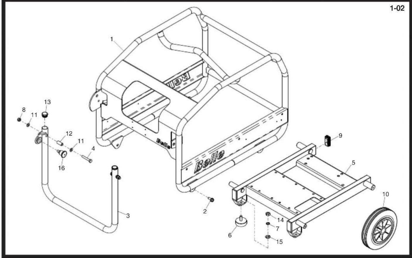
text_image
1-02 Belle 1 8 11 13 12 11 4 16 3 2 9 5 10 6 7 14 15Chassis Assembly, Ensemble Châssis, Conjunto de Chasis, Conjunto do Chassis
| 1 | 02356SIL | Frame - Silver | Châssis - Argent | Estructura - Plata | Estrutura - Prata | 1 |
| 1 | 02356B | Frame - Blue | Châssis - Bleu | Estructura - Azúl | Estrutura - Azul | 1 |
| 1 | 02356AP | Frame - AP Green | Châssis - AP Vert | Estructura - Verde | Estrutura - Verde | 1 |
| 1 | 02356R | Frame - Red | Châssis - Rouge | Estructura - Roja | Estrutura - Vermelho | 1 |
| 1 | 02356Y | Frame - Yellow | Châssis - Jaune | Estructura - Amarilla | Estrutura - Amarelo | 1 |
| 1 | 02356W | Frame - White | Châssis - Blanc | Estructura - Blanco | Estrutura - Branco | 1 |
| 1 | 02356GR | Frame - Grey | Châssis - Gris | Estructura - Gris | Estrutura - Cinza | 1 |
| 2 | 7/8037 | Screw | Vis | Tornillo | Parafuse | M8 x 20 |
| 3 | 02361SIL | Handle - Silver | Poignee - Argent | Manillar - Plata | Punho - Prata | 205594 |
| 3 | 02361B | Handle - Blue | Poignee - Bleu | Manillar - Azúl | Punho - Azul | 205594 |
| 3 | 02363AP | Handle - AP Green | Poignee - AP Vert | Manillar - Verde | Punho - Verde | 205594 |
| 3 | 02361R | Handle - Red | Poignee - Rouge | Manillar - Roja | Punho - Vermelho | 205594 |
| 3 | 02362Y | Handle - Yellow | Poignee - Jaune | Manillar - Amarilla | Punho - Amarelo | 205594 |
| 3 | 02364W | Handle - White | Poignee - Blanc | Manillar - Blanco | Punho - Branco | 205594 |
| 3 | 02361GR | Handle - Grey | Poignee - Gris | Manillar - Gris | Punho - Cinza | 205594 |
| 3 | 02399SIL | Handle - Silver | Poignee - Argent | Manillar - Plata | Punho - Prata | 205595 |
| 3 | 02399B | Handle - Blue | Poignee - Bleu | Manillar - Azúl | Punho - Azul | 205595 |
| 3 | 02399AP | Handle - AP Green | Poignee - AP Vert | Manillar - Verde | Punho - Verde | 205595 |
| 3 | 02399R | Handle - Red | Poignee - Rouge | Manillar - Roja | Punho - Vermelho | 205595 |
| 3 | 02399Y | Handle - Yellow | Poignee - Jaune | Manillar - Amarilla | Punho - Amarelo | 205595 |
| 3 | 02399W | Handle - White | Poignee - Blanc | Manillar - Blanco | Punho - Branco | 205595 |
| 3 | 02399GR | Handle - Grey | Poignee - Gris | Manillar - Gris | Punho - Cinza | 205595 |
| 4 | 9/8014 | Bolt | Boulon | Perno | Perno | M8 x 50 |
| 5 | 02369 | Chassis | Châssis | Chasis | Chassis | 1 |
| 6 | 00525-B | Feet | Pieds | Patas | Pés | 2 |
| 7 | 4/1003 | Washer | Rondelle | Arandela | Anilha | M10 |
| 8 | 8/8008 | Nut | Ecrou | Tuerca | Porca | M8 |
| 9 | 00013 | Plug | Bouchon | Tapón | Bujão | 2 |
| 10 | 60/0285 | Wheel | Roue | Rueda | Roda | 2 |
| 11 | 4/8006 | Washer | Rondelle | Arandela | Anilha | M8 |
| 12 | 02364 | Spacer | Entretoise | Espaciador | Espaçador | 2 |
| 13 | 3/4035 | Plug | Bougie | Tapon | Bujao | 2 |
| 14 | 8/10003 | Nut | Ecrou | Tuerca | Porca | M10 |
| 15 | 4/1005 | Washer | Rondelle | Arandela | Anilha | M10 |
| 16 | 3/0088 | Plunger | Bougie | Tapón | Bujão | 205595 |
BULLDOG
2-01
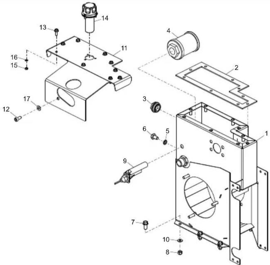
text_image
Exploded view diagram of a mechanical assembly with numbered components for identificationTank Assembly, Ensemble Réservoir, Conjunto Tanque, Conjunto do Despósito
| 1 | 02504....Tank....Réservoir....Tanque....Depósito....1 |
| 2 | 02508....Gasket....Joint....Junta....Gaxeta....1 |
| 3 | 01466....Gauge....Jauge....Calibrar....Ajuizar....1 |
| 4 | 00065....Suction Strainer....Filtre d'aspiration....Tamiz de la Succión....Filtro de Succão....1 |
| 5 | 5/0018....Seal....Joint d'étanchéité....Obturador....Vedação....1 |
| 6 | 7/10013....Screw....Vis....Tornillo....Parafuse....M10 x 16....1 |
| 7 | 7/8037....Screw....Vis....Tornillo....Parafuse....M8 x 20....7 |
| 8 | 8/8008....Nut....Ecrou....Tuerca....Porca....M8....7 |
| 9 | 00790....Switch....Bouton....Parada....Paragem....1 |
| 10 | 4/8006....Washer....Rondelle....Arandela....Anilha....M8....8 |
| 11 | 02507....Cowl....Capot....Caperuza....Cobertura....1 |
| 12 | 10-330-0816....Screw....Vis....Tornillo....Parafuse....M8 x 16....1 |
| 13 | 7/6034....Screw....Vis....Tornillo....Parafuse....M6....1 |
| 14 | 41/00022....Cap....Capuchon....Casquete....Tampa....1 |
| 15 | 8/5001....Nut....Ecrou....Tuerca....Porca....M5....3 |
| 16 | 4/5002....Washer....Rondelle....Arandela....Anilha....M5....3 |
| 17 | 4/8002....Washer....Rondelle....Arandela....Anilha....M8....1 |
MIDI 20-110D, 20-140 & MAJOR 20-140X, 20-160X, 30-140
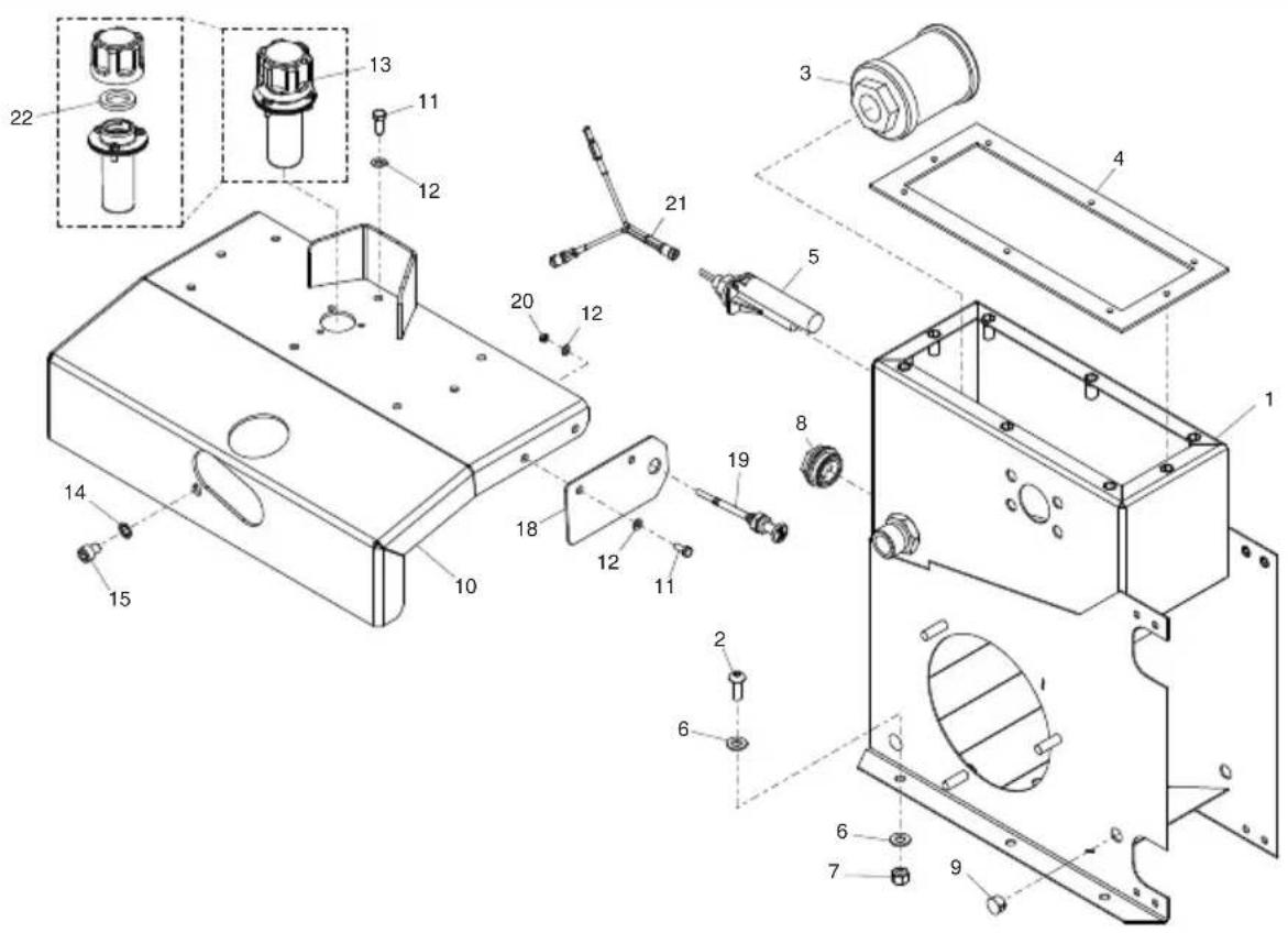
text_image
Exploded view diagram of a mechanical assembly with numbered components for identification2-02
Tank Assembly, Ensemble Réservoir, Conjunto Tanque, Conjunto do Despósito
| 1 | 02368 | Tank | Réservoir | Tanque | Depósito | 1 |
| 2 | 7/8043 | Screw | Vis | Tornillo | Parafuse | M8 x 25. |
| 3 | 00065 | Suction Strainer | Filtre d'aspiration | Tamiz de la Succión | Filtro de Succão | 1 |
| 4 | 02372 | Gasket | Joint | Junta | Gaxeta | 1 |
| 5 | 00790 | Switch | Bouton | Parada | Paragem | 1 |
| 6 | 4/8006 | Washer | Rondelle | Arandela | Anilha | M8 |
| 7 | 8/8008 | Nut | Ecrou | Tuerca | Porca | 6 |
| 8 | 01466 | Gauge | Jauge | Calibrar | Ajuizar | 1 |
| 9 | 01036 | Plug | Bouchon | Tapón | Bujão | 1 |
| 10 | 02360 | Cowl | Capot | Caperuza | Cobertura | 1 |
| 11 | 7/6034 | Screw | Vis | Tornillo | Parafuse | M6 x 16. |
| 12 | 4/6003 | Washer | Rondelle | Arandela | Anilha | 8 |
| 13 | 41/00017 | Cap | Capuchon | Casquete | Tampa | 1 |
| 14 | 00005/3 | Gauge | Jauge | Calibrar | Ajuizar | 1 |
| 15 | 00006 | Seal | Joint d'étanchéité | Obturador | Vedação | 1 |
| 16 | 00007 | Hose | Durit | Flexible | Tubagem | 1 |
| 17 | 01160 | Rivet | Rivet | Roblon | Rebite | 12 |
| 18 | 02373 | Plate | Plaque | Placa | Placa | 1 |
| 19 | 01545 | Emergency Stop | Arrêt d'urgence | Parada de emergencia | Botão de Paragem de Emergência | 1 |
| 20 | 8/6007 | Nut | Ecrou | Tuerca | Porca | 2 |
| 21 | 71/0301 | Harness | Faisceau | Amés | Amés | 1 |
| 22 | 5/0097 | Seal | Joint d'étanchéité | Obturador | Vedação | 1 |
BULLDOG
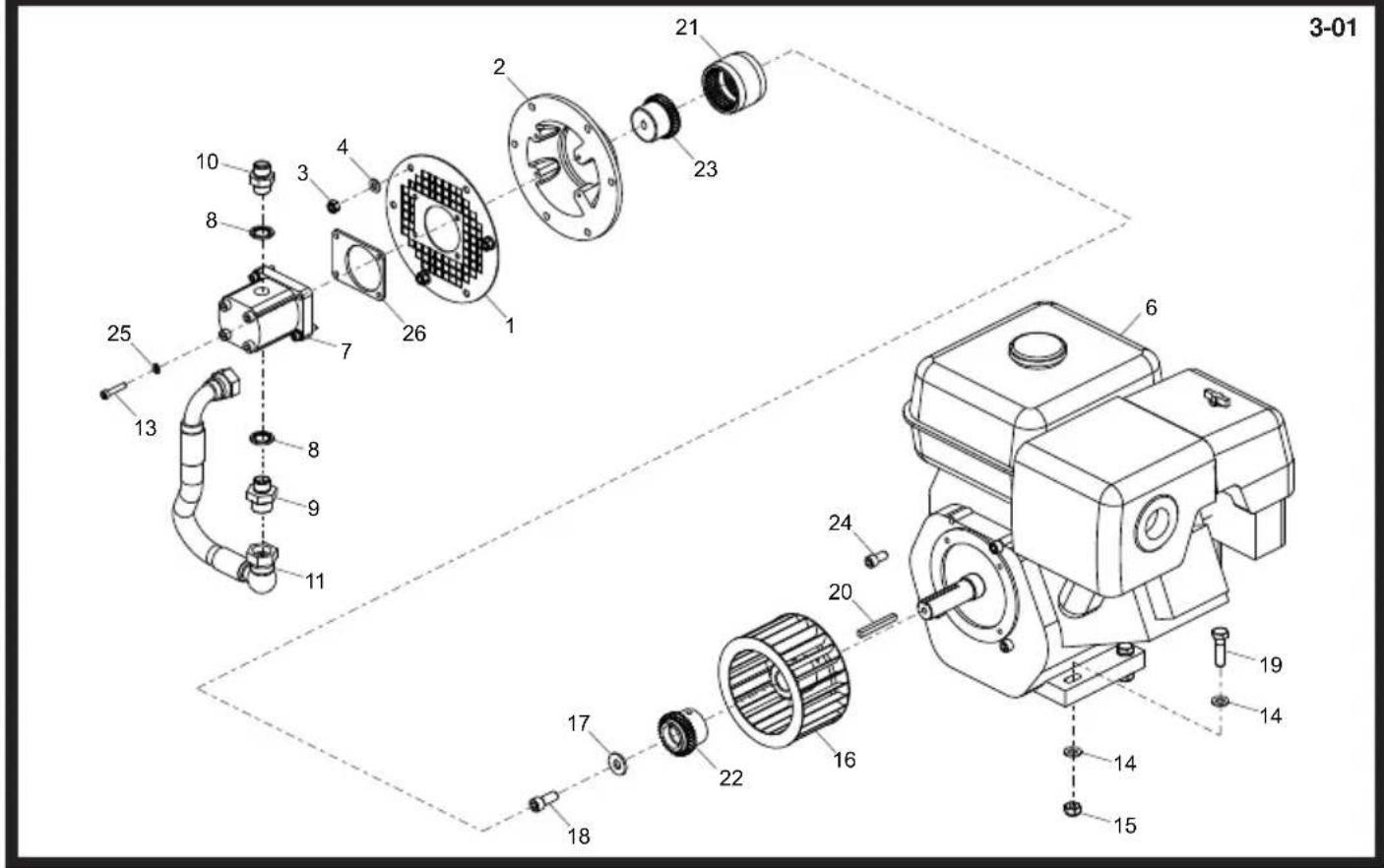
text_image
3-01 21 23 2 26 4 3 8 10 25 13 7 8 9 11 24 6 20 17 18 22 16 14 15 19 14Pump and Motor Assembly, Ensemble Pompe et Moteur, Conjunto de Bombas y Motor, Conjunto da Bomba y Motor
| 1 | 02291 | Guard | Carène | Defensa | Guarda | 1 |
| 2 | 00490-00 | Plate | Plaque | Placa | Placa | 1 |
| 3 | 8/8008 | Nut | Ecrou | Tuerca | Porca | 3 |
| 4 | 4/8006 | Washer | Rondelle | Arandela | Anilha | 3 |
| 6 | 20/0076 | Engine | Moteur | Motor | Motor | 1 |
| 7 | 01069 | Pump | Pompe | Bombas | Bomba | 1 |
| 8 | 5/0002 | Seal | Joint d'étanchéité | Obturador | Vedação | 2 |
| 9 | 6/0006 | Adaptor | Adapteur | Adaptador | Adaptador | 1/2 x 3/8 |
| 10 | 6/0020 | Adaptor | Adapteur | Adaptador | Adaptador | 1/2 x 1/2 |
| 11 | 02313 | Hose | Durit | Flexible | Tubagem | 1 |
| 12 | 4/6001 | Washer | Rondelle | Arandela | Anilha | M6 |
| 13 | 7/6042 | Screw | Vis | Tornillo | Parafuse | M6 x 25 |
| 14 | 4/1005 | Washer | Rondelle | Arandela | Anilha | M10 |
| 15 | 8/10006 | Nut | Ecrou | Tuerca | Porca | M10 |
| 16 | 02510 | Fan | Ventilateur | Ventilador | Ventohina | 1 |
| 17 | 4/1201 | Washer | Rondelle | Arandela | Anilha | M12 |
| 18 | 7/10059 | Screw | Vis | Tornillo | Parafuse | 1 |
| 19 | 9/10030 | Bolt | Boulon | Perno | Perno | M10 x 40 |
| 20 | 21/0430 | Key | Clavette | Chaveta | Chave | 1 |
| 21 | 02513_2 | Sleeve | Manchon | Manguito | Manga | 1 |
| 22 | 02513_1 | Coupling | Accouplement | Acoplamiento | Acoplamento | 1 |
| 23 | 02513_3 | Coupling | Accouplement | Acoplamiento | Acoplamento | 1 |
| 24 | 7/3816 | Screw | Vis | Tornillo | Parafuse | 4 |
| 25 | 4/6004 | Washer | Rondelle | Arandela | Anilha | M6 |
| 26 | 02517 | Plate | Plaque | Placa | Placa | 1 |
MIDI 20-110D
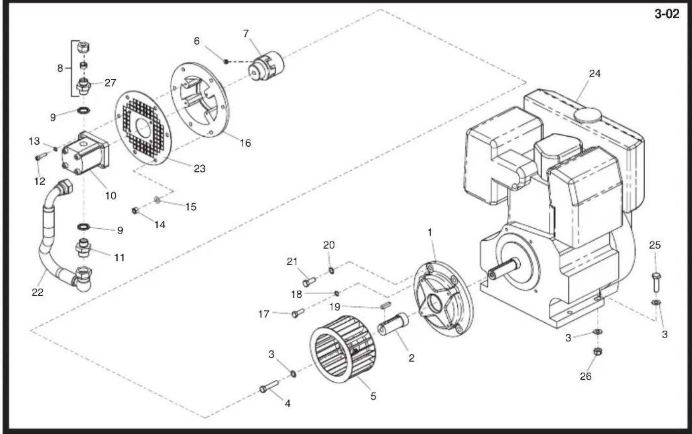
text_image
3-02 8 27 6 7 24 9 13 12 10 23 16 15 14 9 11 22 20 1 21 18 19 17 3 4 5 2 26 3 3 25Pump and Motor Assembly, Ensemble Pompe et Moteur, Conjunto de Bombas y Motor, Conjunto da Bomba y Motor
| 1 | 01859....Spacer.... | Entretoise.... | Espaciador.... | Espaçador.... | 1 |
| 2 | 01133-MD....Shaft.... | Axe.... | Eje.... | Veio.... | 1 |
| 3 | 10-405-1000....Washer.... | Rondelle.... | Arandela.... | Anilha.... | 3 |
| 4 | 01134....Screw.... | Vis.... | Tornillo.... | Parafuse.... | 1 |
| 5 | 01391....Fan.... | Ventilateur.... | Ventilador.... | Ventohina.... | 1 |
| 6 | 10-360-0810....Screw.... | Vis.... | Tornillo.... | Parafuse.... | 1 |
| 7 | 01484....Coupling.... | Accouplement.... | Acoplamiento.... | Acoplamento.... | 1 |
| 8 | 01034....Coupling.... | Accouplement.... | Acoplamiento.... | Acoplamento.... | 1 |
| 9 | 10-100-0513....Seal.... | Joint d'étanchéité.... | Obturador.... | Vedação.... | 2 |
| 10 | 01069....Pump.... | Pompe.... | Bombas.... | Bomba.... | 1 |
| 11 | 6/0006....Adaptor.... | Adapteur.... | Adaptador.... | Adaptador.... | 1 |
| 12 | 7/6013....Screw.... | Vis.... | Tornillo.... | Parafuse.... | 4 |
| 13 | 4/6004....Washer.... | Rondelle.... | Arandela.... | Anilha.... | 4 |
| 14 | 8/8008....Nut.... | Ecrou.... | Tuerca.... | Porca.... | 3 |
| 15 | 4/8006....Washer.... | Rondelle.... | Arandela.... | Anilha.... | 3 |
| 16 | 00490....Plate.... | Plaque.... | Placa.... | Placa.... | 1 |
| 17 | 10-340-0835P...Bolt.... | Boulon.... | Perno.... | Perno.... | 4 |
| 18 | 4/8002....Washer.... | Rondelle.... | Arandela.... | Anilha.... | 4 |
| 19 | 01470....Key.... | Clavette.... | Chaveta.... | Chave.... | 1 |
| 20 | 10-405-1000....Washer.... | Rondelle.... | Arandela.... | Anilha.... | 4 |
| 21 | 10-342-0616P...Screw.... | Vis.... | Tornillo.... | Parafuse.... | 4 |
| 22 | 02313....Hose.... | Durit.... | Flexible.... | Tubagem.... | 1 |
| 23 | 02291....Guard.... | Carène.... | Defensa.... | Guarda.... | 1 |
| 24 | 01870....Engine.... | Moteur.... | Motor.... | Motor.... | 2 |
| 25 | 10-320-1040P...Bolt.... | Boulon.... | Perno.... | Perno.... | 1 |
| 26 | 10-301-1000....Nut.... | Ecrou.... | Tuerca.... | Porca.... | 1 |
| 27 | 6/0020....Adaptor.... | Adapteur.... | Adaptador.... | Adaptador.... | 1 |
MIDI 20-140
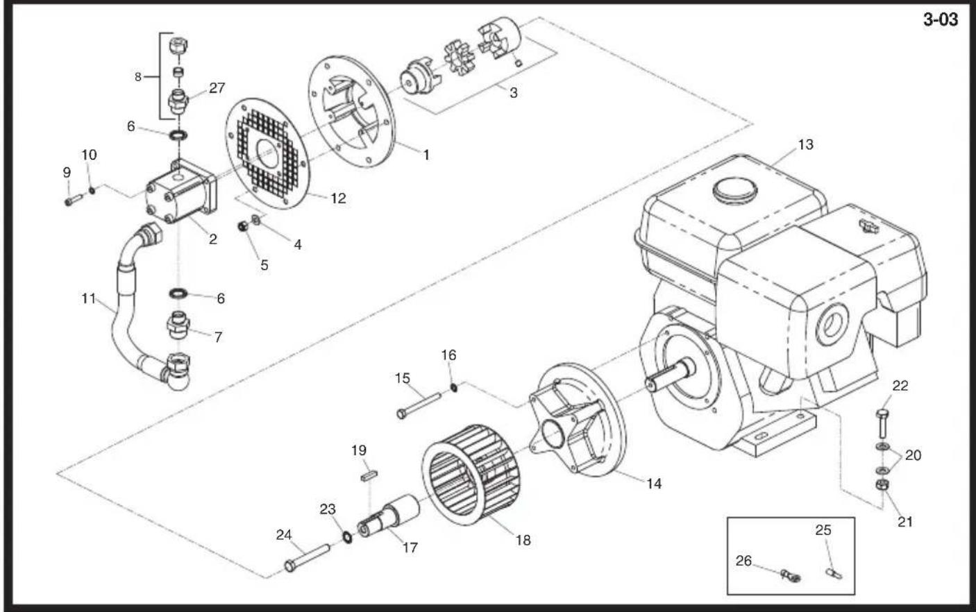
text_image
3-03 1 2 3 4 5 6 7 8 9 10 11 12 13 14 15 16 17 18 19 20 21 22 23 24 25 26Pump and Motor Assembly, Ensemble Pompe et Moteur, Conjunto de Bombas y Motor, Conjunto da Bomba y Motor
| 1 | 00490-00....Plate.... | Plaque.... | Placa.... | Placa.... | 1 | |
| 2 | 01069....Pump.... | Pompe.... | Bombas.... | Bomba.... | 1 | |
| 3 | 01453....Coupling.... | Accouplement.... | Acoplamento.... | Acoplamento.... | 1 | |
| 4 | 4/8006....Washer.... | Rondelle.... | Arandela.... | Anilha.... | M8.... | 3 |
| 5 | 8/8008....Nut.... | Ecrou.... | Tuerca.... | Porca.... | M8.... | 3 |
| 6 | 10-100-0513....Seal.... | Joint d'étanchéité.... | Obturador.... | Vedação.... | 1/2".... | 2 |
| 7 | 6/0006....Adaptor.... | Adapteur.... | Adaptador.... | Adaptador.... | 1/2 x 3/8 M/M.... | 1 |
| 8 | 01034....Coupling.... | Accouplement.... | Acoplamento.... | Acoplamento.... | →Mar '09.... | 1 |
| 9 | 7/6013....Screw.... | Vis.... | Tornillo.... | Parafuse.... | M6 x 25.... | 4 |
| 10 | 4/6004....Washer.... | Rondelle.... | Arandela.... | Anilha.... | M6.... | 4 |
| 11 | 02313....Hose.... | Durit.... | Flexible.... | Tubagem.... | .... | 1 |
| 12 | 02291....Guard.... | Carène.... | Defensa.... | Guarda.... | .... | 1 |
| 13 | 20/0076....Engine.... | Moteur.... | Motor.... | Motor.... | Honda GX270.... | 1 |
| 13 | 02225....Engine.... | Moteur.... | Motor.... | Motor.... | Honda GX270 (USA).... | 1 |
| 13 | 20/0050....Engine.... | Moteur.... | Motor.... | Motor.... | Robin EX27.... | 1 |
| 13 | 02332....Engine.... | Moteur.... | Motor.... | Motor.... | Robin EH41DU.... | 1 |
| 14 | 01858....Spacer.... | Entretoise.... | Espaciador.... | Espaçador.... | .... | 1 |
| 15 | 01469....Bolt.... | Boulon.... | Perno.... | Perno.... | 5/16" x 3.25.... | 1 |
| 16 | 4/8003....Washer.... | Rondelle.... | Arandela.... | Anilha.... | M8.... | 1 |
| 17 | 01454....Shaft.... | Axe.... | Eje.... | Veio.... | .... | 1 |
| 18 | 01391....Fan.... | Ventilateur.... | Ventilador.... | Ventohina.... | .... | 1 |
| 19 | 01470....Key.... | Clavette.... | Chaveta.... | Chave.... | .... | 1 |
| 20 | 10-400-1000....Washer.... | Rondelle.... | Arandela.... | Anilha.... | M10.... | 2 |
| 21 | 10-301-1000....Nut.... | Ecrou.... | Tuerca.... | Porca.... | M10.... | 1 |
| 22 | 10-320-1040P....Screw.... | Vis.... | Tornillo.... | Parafuse.... | M10 x 40.... | 1 |
| 23 | 10-405-1200....Washer.... | Rondelle.... | Arandela.... | Anilha.... | M12.... | 1 |
| 24 | 01471....Bolt.... | Boulon.... | Perno.... | Perno.... | 7/16" x 3.25.... | 1 |
| 25 | 00107....Plug.... | Bougie.... | Tapón.... | Bujão.... | .... | 1 |
| 26 | 00109....Ring.... | Bague.... | Anillo.... | Anel.... | .... | 1 |
| 27 | 6/0020....Adaptor.... | Adapteur.... | Adaptador.... | Adaptador.... | →Apr '09.... | 1 |
MAJOR 20-140X, 20-160X
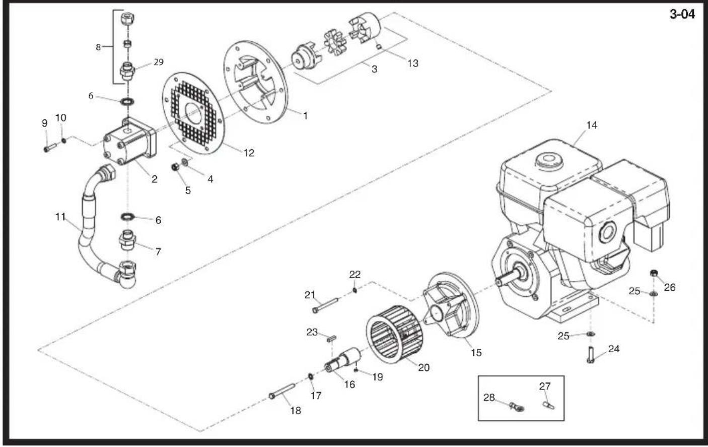
text_image
3-04 8 29 6 10 9 2 12 1 3 13 14 11 6 4 5 7 22 21 23 19 20 15 25 26 25 24 18 17 16 28 27Pump and Motor Assembly, Ensemble Pompe et Moteur, Conjunto de Bombas y Motor, Conjunto da Bomba y Motor
| 1 | 00490-00....Plate....Plaque....Placa....Placa....1 |
| 2 | 01069....Pump....Pompe....Bombas....Bomba....1 |
| 3 | 01453....Coupling....Accouplement....Acoplamiento....Acoplamento....1 |
| 4 | 4/8006....Washer....Rondelle....Arandela....Anilha....3 |
| 5 | 8/8008....Nut....Ecrou....Tuerca....Porca....3 |
| 6 | 10-100-0513....Seal....Joint d'étanchéité....Obturador....Vedação....2 |
| 7 | 6/0006....Adaptor....Adapteur....Adaptador....Adaptador....1 |
| 8 | 01034....Coupling....Accouplement....Acoplamiento....Acoplamento....→Mar '09....1 |
| 9 | 7/6013....Screw....Vis....Tornillo....Parafuse....4 |
| 10 | 4/6004....Washer....Rondelle....Arandela....Anilha....4 |
| 11 | 02313....Hose....Durit....Flexible....Tubagem....1 |
| 12 | 02291....Guard....Carène....Defensa....Guarda....1 |
| 13 | 10-360-0810....Screw....Vis....Tornillo....Parafuse....M8 x 10....1 |
| 14 | 01405....Engine - Honda GX390..Moteur - Honda GX390....Motor - Honda GX390....Motor - Honda GX390....Major 20-140X....1 |
| 14 | 20/0077....Engine - Honda GX390..Moteur - Honda GX390....Motor - Honda GX390....Motor - Honda GX390....Major 20-140X USA....1 |
| 15 | 01858....Spacer....Entretoise....Espaciador....Espaçador....1 |
| 16 | 01454....Shaft....Axe....Eje....Veio....1 |
| 17 | 10-405-1200....Washer....Rondelle....Arandela....Anilha....M12....1 |
| 18 | 10-321-0652....Bolt....Boulon....Perno....Perno....3/82 x 3 1/4"....1 |
| 19 | 10-360-0610....Screw....Vis....Tornillo....Parafuse....M6 x 10....2 |
| 20 | 01391....Fan....Ventilateur....Ventilador....Ventohina....1 |
| 21 | 01469....Bolt....Boulon....Perno....Perno....4 |
| 22 | 4/8002....Washer....Rondelle....Arandela....Anilha....M8....4 |
| 23 | 01470....Key....Clavette....Chaveta....Chav....1 |
| 24 | 7/10009....Screw....Vis....Tornillo....Parafuse....M10 x 40....1 |
| 25 | 4/10001....Washer....Rondelle....Arandela....Anilha....M10....2 |
| 26 | 8/10006....Nut....Ecrou....Tuerca....Porca....M10....1 |
| 27 | 00107....Plug....Bougie....Tapon....Bujao....1 |
| 28 | 00109....Ring....Bague....Anillo....Anel....1 |
| 29 | 6/0020....Adaptor....Adapteur....Adaptador....Adaptador....→Apr '09....1 |
MAJOR 30-140
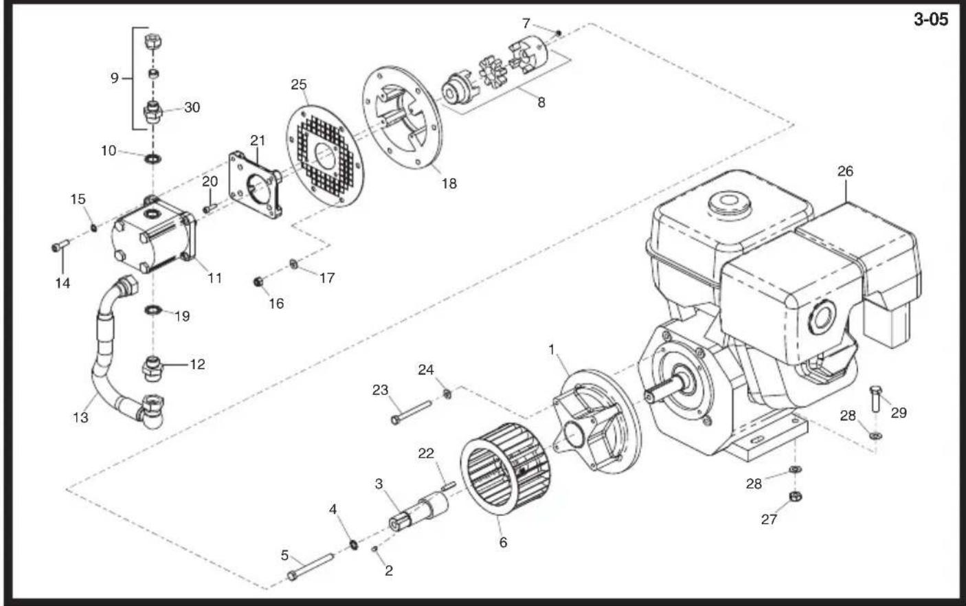
text_image
3-05 9 30 10 20 21 25 7 8 18 15 14 11 16 17 19 12 13 26 23 24 1 22 3 6 4 5 28 29 28 27Pump and Motor Assembly, Ensemble Pompe et Moteur, Conjunto de Bombas y Motor, Conjunto da Bomba y Motor
| 1 | 01858....Spacer.... | Entretoise.... | Espaciador.... | Espaçador.... | 1 |
| 2 | 10-360-0610....Screw.... | Vis.... | Tornillo.... | Parafuse.... | 2 |
| 3 | 02224....Shaft.... | Axe.... | Eje.... | Veio.... | 1 |
| 4 | 10-405-1000....Washer.... | Rondelle.... | Arandela.... | Anilha.... | 1 |
| 5 | 10-321-0660P..Bolt.... | Boulon.... | Perno.... | Perno.... | 1 |
| 6 | 01391....Fan.... | Ventilateur.... | Ventilador.... | Ventohina.... | 1 |
| 7 | 10-360-0810....Screw.... | Vis.... | Tornillo.... | Parafuse.... | 1 |
| 8 | 01653....Coupling.... | Accouplement.... | Acoplamiento.... | Acoplamento.... | 1 |
| 9 | 01034....Coupling.... | Accouplement.... | Acoplamiento.... | Acoplamento....→Mar '09.... | 1 |
| 10 | 10-100-0513....Seal.... | Joint d'étanchéité.... | Obturador.... | Vedação.... | 2 |
| 11 | 02151....Pump.... | Pompe.... | Bombas.... | Bomba.... | 1 |
| 12 | 10-600-1212....Adaptor.... | Adapteur.... | Adaptador.... | Adaptador.... 3/4" × 1/2" .... | 1 |
| 13 | 02313....Hose.... | Durit.... | Flexible.... | Tubagem.... | 1 |
| 14 | 7/8050....Screw.... | Vis.... | Tornillo.... | Parafuse....M8 x 25.... | 4 |
| 15 | 10-405-0800....Washer.... | Rondelle.... | Arandela.... | Anilha.... | 4 |
| 16 | 8/8008....Nut.... | Ecrou.... | Tuerca.... | Porca....M8.... | 3 |
| 17 | 4/8006....Washer.... | Rondelle.... | Arandela.... | Anilha....M8.... | 3 |
| 18 | 00490....Plate.... | Plaque.... | Placa.... | Placa.... | 1 |
| 19 | 5/0003....Seal.... | Joint d'étanchéité.... | Obturador.... | Vedação.... | 1 |
| 20 | 7/6003....Screw.... | Vis.... | Tornillo.... | Parafuse.... | 4 |
| 21 | 01650....Plate.... | Plaque.... | Placa.... | Placa.... | 1 |
| 22 | 01470....Key.... | Clavette.... | Chaveta.... | Chave.... | 1 |
| 23 | 01469....Bolt.... | Boulon.... | Perno.... | Perno.... | 4 |
| 24 | 4/8002....Washer.... | Rondelle.... | Arandela.... | Anilha....8MM.... | 4 |
| 25 | 02291....Guard.... | Carène.... | Defensa.... | Guarda.... | 1 |
| 26 | 01405....Engine - Honda GX390.... | Moteur - Honda GX390.... | Motor - Honda GX390.... | Motor - Honda GX390....Major 30-140.... | 1 |
| 26 | 20/0077....Engine - Honda GX390.... | Moteur - Honda GX390.... | Motor - Honda GX390.... | Motor - Honda GX390....Major 30-140 USA.... | 1 |
| 27 | 8/10006....Nut.... | Ecrou.... | Tuerca.... | Porca....M10.... | 2 |
| 28 | 4/10001....Washer.... | Rondelle.... | Arandela.... | Anilha....M10.... | 4 |
| 29 | 7/10009....Bolt.... | Boulon.... | Perno.... | Perno....M10 x 40.... | 2 |
| 30 | 6/0020....Adaptor.... | Adapteur.... | Adaptador.... | Adaptador......→Apr '09.... | 1 |
BULLDOG
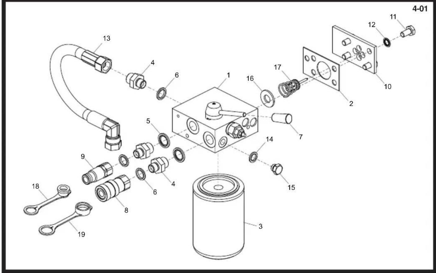
text_image
Exploded view diagram of a mechanical assembly with numbered parts for identificationtext_image
Exploded view diagram of a mechanical assembly with numbered parts and exploded views4-03
Valve Assembly, Distributeur, Conjunto de Válvula, Montagem de Válvula
| 1 | 00803....Gasket....Joint....Junta....Gaxeta....1 |
| 2 | 01392....Valve....Soupape....Valvula....Valvula....1 |
| 3 | 00178....Filter....Filtre....Filtro....Filtro....1 |
| 4 | 10-100-0513....Seal....Joint d'étanchéité....Obturador....Vedação.... 1/2" ....2 |
| 5 | 6/0005....Adaptor....Adapteur....Adaptador....Adaptador.... 1/2 × 3/8 M/M....3 |
| 6 | 5/0007....Seal....Joint d'étanchéité....Obturador....Vedação.... 3/8" ....3 |
| 7 | 5/0011....Seal....Joint d'étanchéité....Obturador....Vedação.... 1/4" ....1 |
| 8 | 6/0039....Adaptor....Adapteur....Adaptador....Adaptador.... 1/4 × 1/4 M/M....1 |
| 9 | 72/0007....Knob....Bouton....Mando....Butão....1 |
| 10 | 00546....Coupling....Accouplement....Acoplamento....Acoplamento....1 |
| 11 | 00545....Coupling....Accouplement....Acoplamento....Acoplamento....1 |
| 12 | 31 & 32....Plug....Bougie....Tapon....Bujao....1 |
| 13 | 00729....Plate....Plaque....Placa....1 |
| 14 | 7/10004....Screw....Vis....Tornillo....Parafuse....M10 x 20....4 |
| 15 | 4/1002....Washer....Rondelle....Arandela....Anilha....M10....4 |
| 16 | 01392-1SP....Spool....Tiroir....Carrete....Carretel....2 |
| 17 | 01392-2SP....Boss....Bossage....Resalto....Ressalto....M8 x 16....1 |
| 18 | 01392-3....Lever....Levier....Palanca....Alavanca....1 |
| 19 | 01477....Pipe....Canalisation....Tubo....Tubo....→Mar '09....1 |
| 20 | 00060-CS....Nut....Ecrou....Tuerca....Porca....→Mar '09....1 |
| 21 | 00047....Adaptor....Adapteur....Adaptador....Adaptador....1 |
| 22 | 10-615-1200....Circlip....Circlip....Resorte circular....Grampo circular....1 |
| 23 | 10-202-6347....O-Ring....Joint torique....Junta tórica....Anel Vedante....1 |
| 24 | 01082....Relief Valve....Clapet de décharge....Válvula de alivio....Válvula de descarga....1 |
| 25 | 10-500-0515....Pin....Goupille....Pasador....Pino....M5 x 15....1 |
| 26 | 10-360-0510....Screw....Vis....Tornillo....Parafuse....M5 x 10....1 |
| 27 | 01392....Valve....Soupape....Válvula....Válvula....1 |
| 28 | 01082/1....O-Ring....Joint torique....Junta tórica....Anel Vedante....1 |
| 29 | 01082/2....Washer....Rondelle....Arandela....Anilha....1 |
| 30 | 01082/3....O-Ring....Joint torique....Junta tórica....Anel Vedante....1 |
| 31 | 00853....Washer....Rondelle....Arandela....Anilha....1 |
| 32 | 00024....Valve....Soupape....Válvula....Válvula....1 |
| 33 | 35/0083....Pipe....Canalisation....Tubo....Tubo....→Apr '09....1 |
| 34 | 6/2026....Cap....Capuchon....Casquete....Tampa....1 |
| 35 | 6/2025....Cap....Capuchon....Casquete....Tampa....1 |
MAJOR 30-140
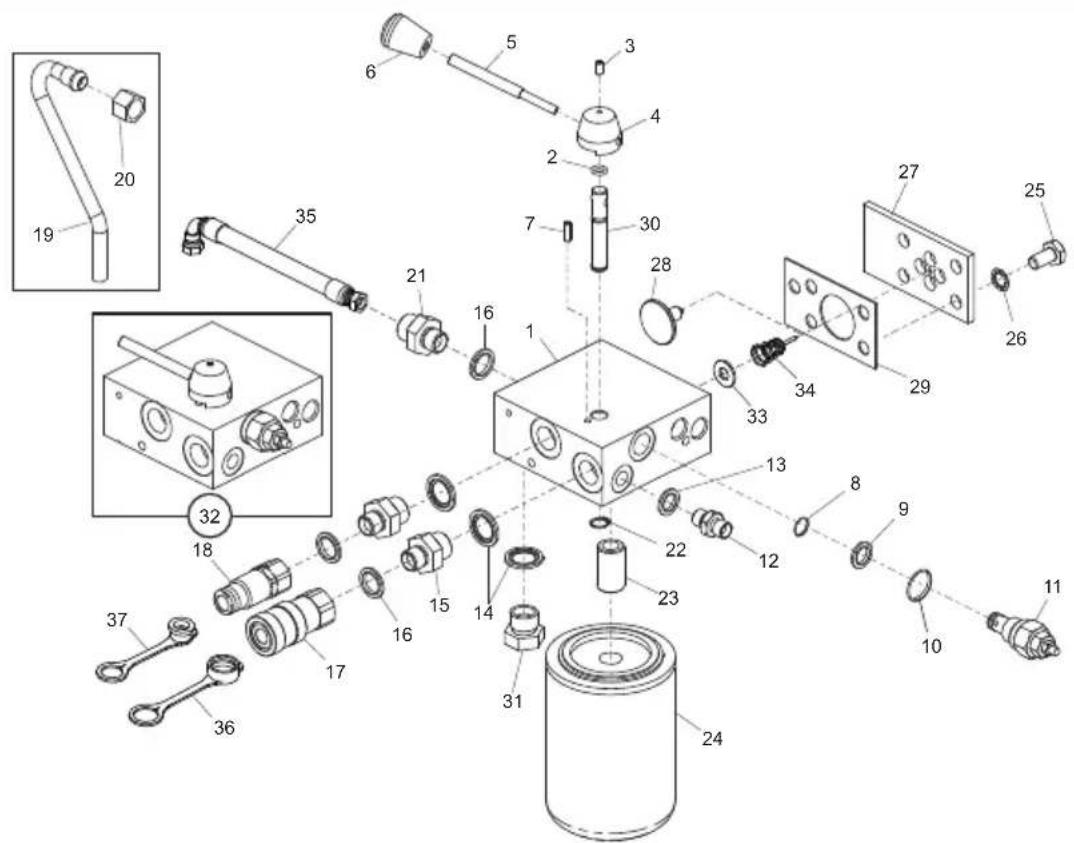
text_image
Exploded view diagram of a mechanical assembly with numbered parts and exploded views4-04
Valve Assembly, Distributeur, Conjunto de Válvula, Montagem de Válvula
| 1 | 01392....Valve.... | Soupape.... | Válvula.... | Válvula.... | 1 |
| 2 | 10-202-6347....O-Ring.... | Joint torique.... | Junta tórica.... | Anel Vedante.... | 1 |
| 3 | 10-360-0510....Screw.... | Vis.... | Tornillo.... | Parafuse....M5 x 10.... | 1 |
| 4 | 00920/2....Boss.... | Bossage.... | Resalto.... | Ressalto.... | 1 |
| 5 | 00920/3....Lever.... | Levier.... | Palanca.... | Alavanca.... | 1 |
| 6 | 72/0007....Knob.... | Bouton.... | Mando.... | Botão.... | 1 |
| 7 | 10-500-0515....Pin.... | Goupille.... | Pasador.... | Pino.... | 1 |
| 8 | 01082/1....O-Ring.... | Joint torique.... | Junta tórica.... | Anel Vedante.... | 1 |
| 9 | 01082/2....Washer.... | Rondelle.... | Arandela.... | Anilha.... | 1 |
| 10 | 01082/3....O-Ring.... | Joint torique.... | Junta tórica.... | Anel Vedante.... | 1 |
| 11 | 01082....Relief Valve.... | Clapet de décharge.... | Válvula de alivio.... | Válvula de descarga.... | 1 |
| 12 | 6/0039....Adaptor.... | Adapteur.... | Adaptador.... | Adaptador.... | 1 |
| 13 | 5/0011....Seal.... | Joint d'étanchéité.... | Obturador.... | Vedação.... 1/4" .... | 1 |
| 14 | 5/0012....Seal.... | Joint d'étanchéité.... | Obturador.... | Vedação.... 1 1/4" .... | 3 |
| 15 | 6/0005....Adaptor.... | Adapteur.... | Adaptador.... | Adaptador.... | 2 |
| 16 | 5/0007....Seal.... | Joint d'étanchéité.... | Obturador.... | Vedação.... 3/8" .... | 3 |
| 17 | 400-02500....Coupling.... | Accouplement.... | Acoplamiento.... | Acoplamento.... | 1 |
| 18 | 400-02600....Coupling.... | Accouplement.... | Acoplamiento.... | Acoplamento.... | 1 |
| 19 | 01658....Pipe.... | Canalisation.... | Tubo.... | Tubo.... Mar '09.... | 1 |
| 20 | 00060-CS....Nut.... | Ecrou.... | Tuerca.... | Porca.... Mar '09.... | 1 |
| 21 | 6/0005....Adaptor.... | Adapteur.... | Adaptador.... | Adaptador.... | 1 |
| 22 | 10-615-1200....Circlip.... | Circlip.... | Resorte circular.... | Grampo circular.... | 1 |
| 23 | 00047....Adaptor.... | Adapteur.... | Adaptador.... | Adaptador.... | 1 |
| 24 | 00178B....Filter.... | Filtre.... | Filtro.... | Filtro.... | 1 |
| 25 | 7/10004....Screw.... | Vis.... | Tornillo.... | Parafuse....M10 x 20.... | 4 |
| 26 | 4/1002....Washer.... | Rondelle.... | Arandela.... | Anilha....M10.... | 4 |
| 27 | 00729....Plate.... | Plaque.... | Placa.... | Placa.... | 1 |
| 28 | 33 & 34....Plug.... | Bougie.... | Tapon.... | Bujao.... | 1 |
| 29 | 00803....Gasket.... | Joint.... | Junta.... | Gaxeta.... | 1 |
| 30 | 01392-1SP....Spool.... | Tiroir.... | Carrete.... | Carretel.... | 1 |
| 31 | 10-601-0800....Plug.... | Bougie.... | Tapon.... | Bujao.... | 1 |
| 32 | 01392....Valve.... | Soupape.... | Válvula.... | Válvula.... | 1 |
| 33 | 00853....Washer.... | Rondelle.... | Arandela.... | Anilha.... | 1 |
| 34 | 00024....Valve.... | Soupape.... | Válvula.... | Válvula.... | 1 |
| 35 | 35/0083....Pipe.... | Canalisation.... | Tubo.... | Tubo.... Apr '09.... | 1 |
| 36 | 6/2026....Cap.... | Capuchon.... | Casquete.... | Tampa.... | 1 |
| 37 | 6/2025....Cap.... | Capuchon.... | Casquete.... | Tampa.... | 1 |
BULLDOG
5-01
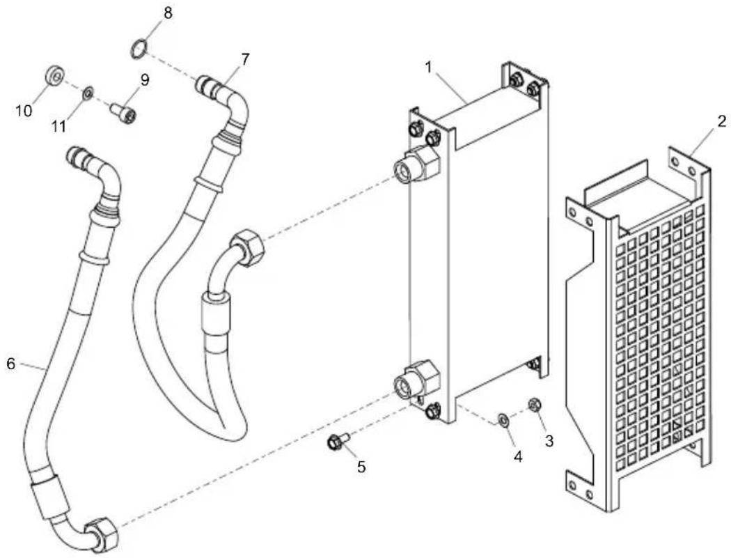
text_image
Technical diagram of a mechanical assembly with numbered components for identificationCooler Assembly, Assemblage de Radiateur, Juego Enfriador, Montagem do Radiador
| 1 | 01414 | Cooler | Refroidisseur | Enfriador | Radiador | 1 |
| 2 | 02371 | Guard | Carène | Defensa | Guarda | 1 |
| 3 | 8/6007 | Nut | Ecrou | Tuerca | Porca | 8 |
| 4 | 4/6003 | Washer | Rondelle | Arandela | Anilha | 8 |
| 5 | 7/6034 | Screw | Vis | Tornillo | Parafuse | 8 |
| 6 | 32/0144 | Hose | Tuyau | Manguera | Tubagem | 1 |
| 7 | 02292 | Hose | Tuyau | Manguera | Tubagem | 1 |
| 8 | 20-202-5157 | O-Ring | Joint torique | Junta tórica | Anel Vedante | 2 |
| 9 | 10-330-0816 | Screw | Vis | Tornillo | Parafuse | 1 |
| 10 | 02301 | Spacer | Entretoise | Espaciador | Espaçador | 1 |
| 11 | 4/8002 | Washer | Rondelle | Arandela | Anilha | 1 |
MIDI 20-110D, 20-140 & MAJOR 20-140X, 20-160X, 30-140
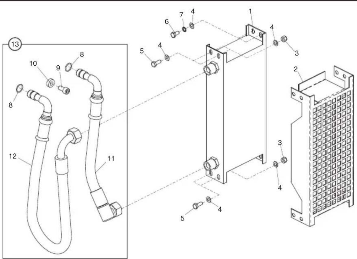
text_image
Technical diagram of a mechanical assembly with numbered components and exploded view, likely for assembly or maintenance.5-02
Cooler Assembly, Assemblage de Radiateur, Juego Enfriador, Montagem do Radiador
| 1 | 01414....Cooler.... | Refroidisseur.... | Enfriador.... | Radiador.... | 1 |
| 2 | 01448....Guard.... | Carène.... | Defensa.... | Guarda.... | 1 |
| 3 | 8/6007....Nut.... | Ecrou.... | Tuerca.... | Porca.... | 6 |
| 4 | 4/6003....Washer.... | Rondelle.... | Arandela.... | Anilha.... | 14 |
| 5 | 9/6001....Screw.... | Vis.... | Tornillo.... | Parafuse.... | 6 |
| 6 | 7/6001....Screw.... | Vis.... | Tornillo.... | Parafuse.... | 2 |
| 7 | 4/6004....Washer.... | Rondelle.... | Arandela.... | Anilha.... | 2 |
| 8 | 10-202-5157....O-Ring.... | Joint torique.... | Junta tórica.... | Anel Vedante.... | 2 |
| 9 | 10-330-0816....Screw.... | Vis.... | Tornillo.... | Parafuse.... | 1 |
| 10 | 02301....Spacer.... | Entretoise.... | Espaciador.... | Espaçador.... | 1 |
| 11 | 02293....Hose.... | Tuyau.... | Manguera.... | Tubagem.... | (20-110D, 20-140, 20-140X, 20-160X) |
| 11 | 02297....Hose.... | Tuyau.... | Manguera.... | Tubagem.... | (30-140).... |
| 12 | 02292....Hose.... | Tuyau.... | Manguera.... | Tubagem.... | 1 |
| 13 | 02295....Hose Kit.... | Kit Durite.... | Juego Manguitos.... | Conjunto de Mangueira.... | (20-110D, 20-140, 20-140X, 20-160X) |
| 13 | 02298....Hose Kit.... | Kit Durite.... | Juego Manguitos.... | Conjunto de Mangueira.... | (30-140).... |
BULLDOG
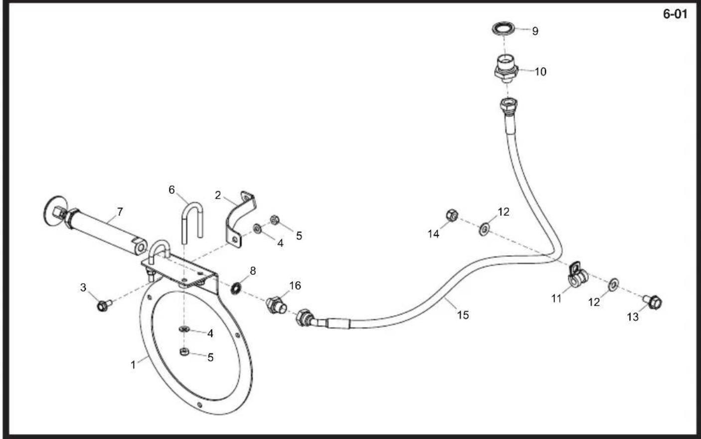
text_image
6-01 9 10 12 14 15 11 12 13 1 2 3 4 5 6 7 8 9 10 11 12 13 14 15 16 4 5text_image
Technical diagram of a device casing with numbered components and labeled partsTool Tray, Bac à Outils, Bandeja de Herramientas, Bandeja de Ferramentas
| 1 | 02391SL....Tray....Bac....Bandeja....Bandeja....1 |
| 2 | 7/8037....Screw....Vis....Tornillo....Parafuso....M8 x 20....3 |
| 3 | 4/8006....Washer....Rondelle....Arandela....Anilha....M8....3 |
| 4 | 8/8008....Nut....Ecrou....Tuerca....Porca....M8....3 |
| 5 | 800/99952....Decal....Autocollant....Rótulo....Decalque....Altrad Logo....1 |
| 6 | 800/99556....Decal....Autocollant....Rótulo....Decalque....1 |
| 7 | OPH-01-DIO....Tool Tray....Bac à Outils....Bandeja de Herramientas....Bandeja de Ferramentas....1 |
BULLDOG, MIDI 20-110D, 20-140 & MAJOR 20-140X, 20-160X, 30-140

text_image
7-01 1 2 3 4 5 6 4 2 3 5 6Hose Assembly, Assemblage de la Durite, Con. de Manguera, Montagem de Mangueira
text_image
Technical diagram of a portable gas generator with numbered components for identificationMIDI & MAJOR BULLDOG
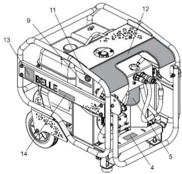
text_image
11 9 12 13 BELLER 14 5 4Decals, Autocollant, Rótulo, Decalque
| 1 | 800/99758 | Decal | Autocollant | Rótulo | Decalque | 1 |
| 2 | 800/99764 | Decal | Autocollant | Rótulo | Decalque | 1 |
| 2 | 800/99761 | Decal | Autocollant | Rótulo | Decalque | 1 |
| 2 | 800/99765 | Decal | Autocollant | Rótulo | Decalque | 1 |
| 2 | 800/99766 | Decal | Autocollant | Rótulo | Decalque | 1 |
| 2 | 800/99792 | Decal | Autocollant | Rótulo | Decalque | 1 |
| 3 | 800/00300 | Decal | Autocollant | Rótulo | Decalque | 1 |
| 4 | 02354 | Decal - Filter | Autocollant - Filtre | Rótulo - Filtro | Decalque - Filtro | 1 |
| 5 | 01888 | Decal - Hydraulic Filter | Autocollant - Filtre Hydraulique | Rótulo - Filtro Hidráulico | Decalque - Filtro Hidráulico | 1 |
| 6 | 800/99767 | Decal | Autocollant | Rótulo | Decalque | 1 |
| 6 | 800/99768 | Decal | Autocollant | Rótulo | Decalque | 1 |
| 7 | 01547 | Decal | Autocollant | Rótulo | Decalque | 1 |
| 8 | 800/99838 | Decal - Noise | Autocollant - Bruits | Rótulo - Ruidos | Decalque - Ruído | 101 dB(A) |
| 8 | 01621 | Decal - Noise | Autocollant - Bruits | Rótulo - Ruidos | Decalque - Ruído | 104 dB(A) |
| 9 | 01964 | Decal - Oil Gauge | Autocollant - Nivel de aceite | Rótulo - Vareta de medição de óleo | Decalque - Olieplug | 1 |
| 10 | 01965 | Decal - Throttle | Autocollant - Accélérateur | Rótulo - Acelerador | Decalque - Estrangulador | 1 |
| 11 | 02349 | Decal | Autocollant | Rótulo | Decalque | Red Dot |
| 12 | 800/99319 | Decal | Autocollant | Rótulo | Decalque | Bulldog Big |
| 13 | 800/99318 | Decal | Autocollant | Rótulo | Decalque | Altrad Logo |
| 14 | 800/99320 | Decal | Autocollant | Rótulo | Decalque | Bulldog Text |