BELLE Vibratech+ 58 - Vibratory construction tool ALTRAD - Free user manual and instructions
Find the device manual for free BELLE Vibratech+ 58 ALTRAD in PDF.
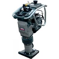
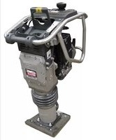
| Product type | Vibrating needle with motor in the head |
| Application | Concrete compaction |
| Brand | Altrad |
| Model | BELLE Vibratech+ 58 |
| Needle diameter | 58 mm |
| Needle length | 410 mm |
| Weight (with 7 m cable) | 19 kg |
| Weight (with 10 m cable) | 24 kg |
| Vibration frequency | 200 Hz |
| Vibrations per minute | 12000 VPM |
| Centrifugal force | 5075 N |
| Power | 1.5 kW |
| Nominal voltage | 230 V (single-phase) |
| Nominal current | 3.0 A |
| Protection rating | 44-57 |
| Vibration level | 1.99 m/s² |
| Power supply | Mains, grounding required |
| Main functions | Concrete compaction by vibration, electronic converter with LED display |
| Maintenance and cleaning | Clean after use, check needle wear, periodic maintenance by a professional |
| Safety | Grounding, protection against overload, short circuit, overheating; use PPE |
| Spare parts and repairability | Use original Altrad Belle parts; repair by an authorized dealer |
| General information | 12-month warranty, CE declaration of conformity |
Frequently Asked Questions - BELLE Vibratech+ 58 ALTRAD
User questions about BELLE Vibratech+ 58 ALTRAD
0 question about this device. Answer the ones you know or ask your own.
Ask a new question about this device
Download the instructions for your Vibratory construction tool in PDF format for free! Find your manual BELLE Vibratech+ 58 - ALTRAD and take your electronic device back in hand. On this page are published all the documents necessary for the use of your device. BELLE Vibratech+ 58 by ALTRAD.
USER MANUAL BELLE Vibratech+ 58 ALTRAD
natural_image
Line drawing of a handheld electrical tool with coiled cable and ring (no text or symbols)GB Operators Manual
F Manuel De L'Opérateur
D Bedienungshandbuch
NO Betjene Håndbok
SF Käyttöohje
PL Instrukcja Obstugi
6
14
22
30
38
46
- Spare Parts Book
- Pièces Détachées
- Ersatzteilhandbuch
- Bruksanvisning
- Varaosaluettelo
- Lista Części Zamiennych
54
EC DECLARATION OF CONFORMITY / DECLARATION CE DE CONFORMITE / DECLARACIÓN DE CONFORMIDAD CE / DECLARAÇÃO CE DE CONFORMIDADE / EG-VERKLARING VAN OVEREENSTEMMING / EF OVERENSSTEMMELSESERKLAERING

We, Belle Group Sheen UK, Sheen, Nr. Buxton, Derbyshire, SK17 0EU, GB, hereby certify that if the product described within this certificate is bought from an authorised Belle Group dealer within the EEC, it conforms to the following EEC directives: 2006/42/CE (This directive replaces directive 98/37/EC), Electromagnetic Compatibility Directive 2004/108/CE (as amended by 89/336/EEC, 92/31/EEC & 93/68 EEC). The Waste Electrical and Electronic Equipment (WEEE) 2002/96/CE, the low voltage directive 2006/95/CE, BS EN ISO 12100-1:2003 Safety of machinery and associated harmonised standards, where applicable. Noise emissions conform to directive 2000/14/EC Annex VI, for machines under article 12 the notified body is AVT Reliability, Unit 2 Easter Court, Europa Boulevard, Warrington, Cheshire, WA5 7ZB, GB Noise Technical files are held by Ray Neilson at the Belle group Head Office address which is stated above.

PRODUCT TYPE ...... TYPE DE PRODUIT...... TIPO DE PRODUCTO......
MODEL...... MODELE...... MODELO......
SERIAL No..... N° DE SERIE..... N° DE SERIE.....
natural_image
Empty white rectangle with dashed border (no text or symbols)Signed by:
Signature:
Medido por:
Assinado por:
Getekend door:
Uunderskrevetaf:

text_image
O.NahRay Neilson
Managing Director - On behalf of BELLE GROUP (SHEEN) UK.
Date of Declaration - 2018
natural_image
Empty white rectangle with dashed border (no text or symbols)Unterzeichnet vo:
Firmato da:
Undertecknat:
Signatur:
Allekirjoitus:
Podpisat:

text_image
O.NahRay Neilson
natural_image
Empty rectangular frame with dashed border (no text or symbols)Podepsal:
Semnat de:
Aláírás:
Potpisao:
Imzalayan:
Podpísal:

text_image
O. Nath Ray NeilsonDirector General - in numele BELLE GROUP (SHEEN), UK
PRODUKTA TIPS ......
МОДЕЛЬ......
MUDEL ....
MODELIS......
natural_image
Empty white rectangle with dashed border (no text or symbols)Подпись:
Alla kirjutanud:
Paraksts:
Pasiraše:
Подпис:
Υπογραφή:

text_image
O.NahRay Neilson
This manual has been written to help you operate and service the Vibratech+ High Frequency Poker safely. This manual is intended for dealers and operators of the Vibratech+ High Frequency Poker.
Foreword
The ‘Machine Description’ section helps you to familiarise yourself with the machine's layout and controls.
The ‘General Safety’ and ‘Health and Safety’ sections explain how to use the machine to ensure your safety and the safety of the general public.
The ‘Trouble Shooting Guide’ helps you if you have a problem with your machine.
The ‘Service & Maintenance’ section is to help you with the general maintenance and servicing of your machine.
The 'Warranty' Section details the nature of the warranty cover and the claims procedure.
The ‘Declaration of Conformity’ section shows the standards that the machine has been built to.
Directives with regard to the notations.
Text in this manual to which special attention must be paid are shown in the following way:

CAUTION
The product can be at risk. The machine or yourself can be damaged or injured if procedures are not carried out in the correct way.

WARNING
The life of the operator can be at risk.
GB
WARNING

WARNING
Before you operate or carry out any maintenance on this machine YOU MUST READ and STUDY this manual.
KNOW how to safely use the unit's controls and what you must do for safe maintenance. (NB Be sure that you know how to switch the machine off before you switch on, in case you get into difficulty.)
ALWAYS wear or use the proper safety items required for your personal protection. If you have ANY QUESTIONS about the safe use or maintenance of this unit, ASK YOUR SUPERVISOR OR CONTACT: ALTRAD BELLE (UK): +44 (0) 1298 84606
GB
Contents
How to use this manual....6
Warning 6
Machine Description....7
Technical Data....7
General Safety 8 - 9
Health and Safety....9
Pre-Start Checks 10
Operation....10
Service & Maintenance ....11
Trouble Shooting Guide 12
LED Display Panel 12
Storage 12
Transportation 12
Warranty 13
Declaration of Conformity....2
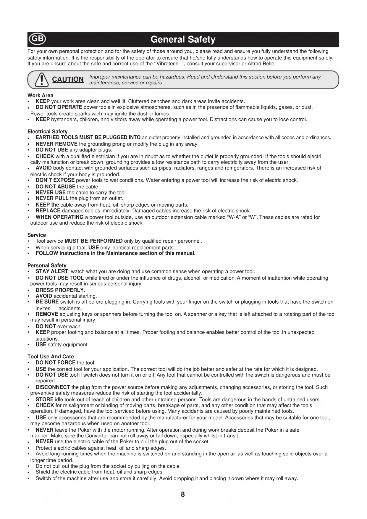
Machine Description
Type: Vibrating poker with motor in head. Application: Compacting of concrete
- Poker Head
- Protective Rubber Hose (7m or 10m)
- Electronic Converter Housing
- Connection Cable (15m)
- Connection Plug
- Start / Stop Button
- LED Display Panel (see LED Display Panel section of the manual for more details)
text_image
Button Panel (see LED Display on of the manual for more 1 2 3 4 5 6 7Technical Data

| Model 38 42 52 58 | ||||
| Weight - 7M (kg) 12 15 17 19 | ||||
| Weight - 10M (kg) 16 19 22 24 | ||||
| Poker Diameter (mm) 38 42 52 58 | ||||
| Poker Length (mm) 330 348 382 410 | ||||
| Frequency (Hz) 200 200 200 200 | ||||
| Current (A) 1.3 1.8 2.6 3.0 | ||||
| Vibrations Per Minute (VPM) | 12000 | 12000 | 12000 | 12000 |
| Force Output (N) | 1825 | 2450 | 3420 | 5075 |
| Power (kW) | 1.5 1.5 1.5 | 1.5 | ||
| IP Rating | 44 - 57 | 44 - 57 | 44 - 57 | 44 - 57 |
| Vibration Level (m/sec ^2 ) | 2.13 | 2.10 | 1.77 | 1.99 |
For your own personal protection and for the safety of those around you, please read and ensure you fully understand the following safety information. It is the responsibility of the operator to ensure that he/she fully understands how to operate this equipment safely. If you are unsure about the safe and correct use of the “Vibratech+”, consult your supervisor or Altrad Belle.

CAUTION
Improper maintenance can be hazardous. Read and Understand this section before you perform any maintenance, service or repairs.
Work Area
- KEEP your work area clean and well lit. Cluttered benches and dark areas invite accidents.
• DO NOT OPERATE power tools in explosive atmospheres, such as in the presence of flammable liquids, gases, or dust.
Power tools create sparks wich may ignite the dust or fumes. - KEEP bystanders, children, and visitors away while operating a power tool. Distractions can cause you to lose control.
Electrical Safety
• EARTHED TOOLS MUST BE PLUGGED INTO an outlet properly installed and grounded in accordance with all codes and ordinances.
- NEVER REMOVE the grounding prong or modify the plug in any away.
• DO NOT USE any adaptor plugs.
- CHECK with a qualified electrician if you are in doubt as to whether the outlet is properly grounded. If the tools should electrically malfunction or break down, grounding provides a low resistance path to carry electricity away from the user.
- AVOID body contact with grounded surfaces such as pipes, radiators, ranges and refrigerators. There is an increased risk of electric shock if your body is grounded.
• DON'T EXPOSE power tools to wet conditions. Water entering a power tool will increase the risk of electric shock.
• DO NOT ABUSE the cable.
• NEVER USE the cable to carry the tool.
• NEVER PULL the plug from an outlet.
- KEEP the cable away from heat, oil, sharp edges or moving parts.
- REPLACE damaged cables immediately. Damaged cables increase the risk of electric shock.
- WHEN OPERATING a power tool outside, use an outdoor extension cable marked "W-A" or "W". These cables are rated for outdoor use and reduce the risk of electric shock.
Service
• Tool service MUST BE PERFORMED only by qualified repair personnel.
- When servicing a tool, USE only identical replacement parts.
• FOLLOW instructions in the Maintenance section of this manual.
Personal Safety
• STAY ALERT, watch what you are doing and use common sense when operating a power tool.
- DO NOT USE TOOL while tired or under the influence of drugs, alcohol, or medication. A moment of inattention while operating power tools may result in serious personal injury.
• DRESS PROPERLY.
• AVOID accidental starting.
- BE SURE switch is off before plugging in. Carrying tools with your finger on the switch or plugging in tools that have the switch on invites accidents.
- REMOVE adjusting keys or spanners before turning the tool on. A spanner or a key that is left attached to a rotating part of the tool may result in personal injury.
• DO NOT overreach.
- KEEP proper footing and balance at all times. Proper footing and balance enables better control of the tool in unexpected situations.
• USE safety equipment.
Tool Use And Care
• DO NOT FORCE the tool.
• USE the correct tool for your application. The correct tool will do the job better and safer at the rate for which it is designed.
- DO NOT USE tool if switch does not turn it on or off. Any tool that cannot be controlled with the switch is dangerous and must be repaired.
- DISCONNECT the plug from the power source before making any adjustments, changing accessories, or storing the tool. Such preventive safety measures reduce the risk of starting the tool accidentally.
• STORE idle tools out of reach of children and other untrained persons. Tools are dangerous in the hands of untrained users.
- CHECK for misalignment or binding of moving parts, breakage of parts, and any other condition that may affect the tools operation. If damaged, have the tool serviced before using. Many accidents are caused by poorly maintained tools.
- USE only accessories that are recommended by the manufacturer for your model. Accessories that may be suitable for one tool, may become hazardous when used on another tool.
- NEVER leave the Poker with the motor running. After operation and during work breaks deposit the Poker in a safe manner. Make sure the Convertor can not roll away or fall down, especially whilst in transit.
• NEVER use the electric cable of the Poker to pull the plug out of the socket.
- Protect electric cables against heat, oil and sharp edges.
- Avoid long running times when the machine is switched on and standing in the open air as well as touching solid objects over a longer time period.
- Do not pull out the plug from the socket by pulling on the cable.
- Shield the electric cable from heat, oil and sharp edges.
- Switch of the machine after use and store it carefully. Avoid dropping it and placing it down where it may roll away.
General Safety
Before operation
Intended use:
- The Poker must only be used for the intended purpose, which means for the compression of concrete of various consistencies. Any other type of use is not in accordance with the intended use and is therefore the sole responsibility of the respective company.
- The frequency inverter is a voltage source inverter (VSI) with fully digitalised microprocessor technique. It works in pulse width modulation (PWM), which assures the trouble-free run of connected equipments. IGBT (Integrated Gate Bipolar Transistors) reduce the power dissipation (moderate warmth develops) of the transient loss in the power unit.
- The new CCDS-system (Current Control Dynamic Scan) will not permit a switch-off of the frequency inverter in the case of an over load.
• Another protection for the frequency inverter is the short circuit immunity.
• An integrated motor-protection (l x t) and software-adapted limitation of the current offer a high protection for the drive. - EMC is an important criterion and therefore we use an aluminium chassis as protective umbrella as the best protection against interference immunity and interference emissions.
- Integrated entry- and exit filters are standard.
• The machine corresponds with protection class 1 (earth wire).
Health and Safety

For your own safety, as protection for others, and to avoid damage to the motor, read carefully the following usage recommendations.
- For the safe and proper operation of the "Vibratech+", make sure that operators have been instructed in the correct use of this machine.
- Before connecting the motor to the electrical system, make sure that the voltage and frequency match with the ones stated on the machine serial plate.
• ENSURE that all housing screws are tight before starting work. - AVOID the flattening of the cable by heavy machinery with could cause breakage.
• DO NOT OPERATE the motor when this is working and without transmission.
• DO NOT WORK poker in bad conditions, the motor overheats.
• DO NOT WORK with the cast housing broken.
• DO NOT PERMIT untrained personnel to operate the motor or connections.
• MAINTAIN free ventilation of air. - KEEP the Poker in a clean and dry area.
• MAKE SURE that the electrical cable is with the proper section and functioning properly. - BEFORE DOING any type of repair, DISCONNECT the Poker from the electrical system.
- WHEN FINISHING the job or when taking a break, the operator should unplug, disconnect it from the electrical system, and have it placed in such a way that it should not fall or tip.
- Pokers with an integrated converter must only be connected to the voltage and frequency indicated on the power rating plate. Rating plates can be found on the outside and inside of the inverter chassis.
• The machine must only be operated when all protective devices are in place.
• The use of Vibratech+ Pokers is not permitted in an environment where there is a danger of explosions. - Ensure that all parts of the machine are bolted and secured before operating.
• In addition, all local regulations should be respected.
Vibration
Some vibration from the poker is transmitted through the flexible hose to the operator's hands.
PPE (Personal Protective Equipment).
Suitable PPE must be worn when using this equipment i.e. Safety Goggles, Gloves, Ear Defenders, Dust Mask and Steel Toe capped footwear. Wear clothing suitable for the work you are doing. Always protect skin from contact with concrete. Suitable ear defenders Should be used.
Measure to ensure the EMC
The machine fulfils all requirements for industrial use with regards to interference immunity and interference emissions, as long as all measures in the Operators Manual are observed.
Grounding and Potential Equalisation
The correct and proper grounding assures the protection of people from dangerous voltage points (entry, exit, and intermediate circuit voltage) and through the leakage of parasitic currents and the low impedance potential equalisation it is an important instrument for the reduction of electromagnetic influences.
Filtering
Filters are fitted into the transmission path between the source of interference and the susceptible device. Their function is to reduce the emissions from conductors and to increase interference immunity. For this reason the machine is fitted with net filters and throttles.
Shielding
It serves the un-coupling of fields between two spatial areas. It helps to reduce the emissions of electromagnetic radiation and increases the interference immunity. The consistent use of metallic chassis is one of the most important measures to assure EMC.
Linking into motor conductors.
The inductive input-coupling in an electric circuit can be reduced considerably by using twisted conductors. Capacitive, inductive and electromagnetic input-couplings must be reduced by using shields for the cables. Only such shields used on both sides will reduce the inductive and high frequency electromagnetic input-coupling.
GB
Pre-Start Checks
• Before starting the job, check the correct working of all the handling and safety devices.
- If defects are found in the safety devices or other defects which could reduce the safe handling of the equipment, stop working and notify to the proper responsible person.
• Inspect cables regularly for damage.
- Check existing plugs and sockets regularly. Keep contact pins and sockets clean and undistorted for a free current transmission.
- Inspect Vibrator Head and Eccenter Tube for wear. Replace defective parts if necessary.
- Stop operation immediately in case of defects that could affect the safety during operation.
GB
Operation
Through switching on the machine, the voltage and frequency will be booted up synchronously with the nominal par (soft start-up).
Thus, critical current strength at the point of switching on will be prevented.
NOTE:-
The Poker with integrated inverter can be connected to an electric generator aggregate under the following conditions:
- The operating voltage of the generator must be in any loading case between 230 + 15%;
- The machine must be operated alone on the generator aggregate;
- The manufacturer of the generator aggregate must permit the operation of consumers with condensers.
Switching off:
Switch off the Poker with integrated inverter first. Only after that pull out the electric connector from the plug.
VIBRATING POKER CONNECTION TO POKER
The poker has a plug to connect the vibrating pokers.
-
Connect the Poker to the electrical supply, ensure that the connection is correct (specification and condition of cable according to standards of security).
-
To disconnect, switch off the Poker with the switch.
-
Finally remove the Poker plug from the electrical supply.
Connection possibilities:
Make sure the total current (A) does not exceed the out put current specified in the electrical characteristic of the Poker.
EXTENSION CABLES
Use three phase cables with the appropriate plugs. If in doubt, consult a qualified electrician.

CAUTION
DO NOT use damaged or worn out cables.
AVOID heavy loads on the cables.
RECOMMENDATIONS OF USE OF CONCRETE CONVERTOR
- Choose the right size of poker for: the size of the job, the spacing of reinforcement, slump of the concrete and the mix design.
- It is recommended to have an additional concrete convertor available.
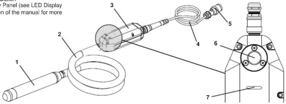
- Pour the concrete evenly, into the form work, in 300-500 mm thick layers. Do not use the poker convertor to spread the concrete.
- Vibrate the concrete systematically. Make 300-500 mm vertical insertions at intervals of 8 - 10 times the tube diameter. Where possible, push the poker convertor about 150 mm into the previous layer of the concrete, this will help obtain the best level of bonding between the two layers.
The concrete has been thoroughly vibrated when the surface around the poker is shiny and no large air bubbles rise to the surface of the concrete. This normally takes 10 - 20 seconds at each location of the poker.
-
Withdraw the poker slowly so that the concrete can flow into the void left by the poker.
-
Do not push or force the convertor against the reinforcement. Keep a distance of 70 mm minimum from the walls.
-
Always remove the poker vertically, so the concrete fills the empty space again. Do not switch off until the poker is withdrawn. The speed of removal is approximately 80 mm per second. When the convertor is almost out, extract quickly to avoid shaking the surface.
text_image
8-10 x Ø 300-500mm 150mmService & Maintenance
The Altrad Belle ‘Vibratech+’ is designed to give many years of trouble free operation. It is, however, important that the simple regular maintenance listed in this section is carried out.
It is recommended that an approved Altrad Belle dealer carries out all major maintenance and repairs. Always use genuine Altrad Belle replacement parts, the use of spurious parts may void your warranty.
Because of various risks with regards to cleanliness we advise against washing and then applying new grease onto used and dismantled bearings during maintenance works and assembling them again. We recommend instead the use of original and new grooved ball bearings or Poker bearings from Altrad Belle; these are already greased as required.
Service, connection and assembly may be accomplished only on the condition that:-
- The electrical installation is dead.
- Protected against reconnection.
- All drives are in the STOP position.
In switch-on position, electrical installations and machinery contain live, naked wires or rotating parts. This could result in personal injury and material damage should the covers and protection devices be removed contrary to regulations. This could also happen under wrong handling and maintenance or misapplication. Dealing with devices equipped with power electronics the expert might come across another uncommon danger which so far he may not have encountered, i.e. the device still contains electrical voltage even after the supply voltage has been cut off.

WARNING
Observe the waiting period before opening the 'Vibratech+' Poker. In addition to the time of discharge, which is about 90 seconds, wait and check for any residual voltage prior to starting work. The waiting period is at least 2 minutes after the plug has been disconnected.
- During clamping work on the terminal board, the Poker must be dead.
- According to EC standards concerning the electro-magnetic compatibility, the electro-magnetic interferences are to be reduced by using cable screens, cable section 1.5mm ^2 . Cable screening must be done on both sides.
Periodic Maintenance
- Only a qualified electrician should work on the electrical parts.
- Disconnect the Poker from the power supply before conducting any maintenance.
- In all maintenance operations, original parts will be used.
- If you have replaced the switch, ensure the bolts are tightened and the box is watertight.
- After maintenance jobs all the parts must be assembled correctly.
- Every 12 month or more frequently, depending on the use, it is recommended an inspection be conducted by an authorised dealer.
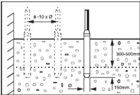
- Monitor the wear of the poker by measuring the outside diameter (B) and length (A). Replace the housing or cap when the diameter or length, in the smallest point, is less than the dimension specified in the table according to the model:
text_image
A BDIMENSIONS OF WEAR FOR DIAMETERS AND LENGTHS OF THE POKER
a. The minimum dimensions are printed in bold.
b. The dimensions in brackets are the original dimensions.
c. Replace the housing when it reaches the minimum diameter.
d. Replace the tip when it reaches the minimum length.
| Model Diameter (mm) Length (mm) | |
| 38 36.5 (38) 325 (330) | |
| 42 40.5 (42) 343 (348) | |
| 52 50.5 (52) 378 (382) | |
| 58 56.5 (58) 405 (410) | |
Troubleshooting Guide
| Problem Cause / Solution | |
| The poker is not working | 1. Verify if there is current |
| 2. Plug in bad conditions | |
| 3. Defective switch | |
| 4. Connections in bad conditions | |
| The poker works correctly but it overheats | 1. Check the poker in not working out of concrete |
| 2. Verify the output voltage of the Poker | |
| 3. Bearing in bad condition or without grease. | |
| The poker works slowly and it overheats | 1. Verify the out put voltage and frequency of the Poker |
| 2. Check the specifications of the extensions cables | |
| The motor is noisy 1. Bearing are not in good conditions | |

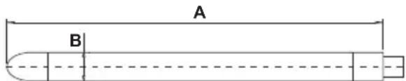
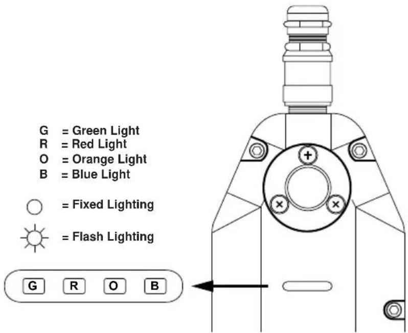
LED Display Panel
| No. Power On | G |
| 1 Action |  |
| 2 Short Circuit | [0849] |
| 3 Overvoltage |  |
| 4 Current Leaking |  |
| 5 Overheating |  |
| 6 Overcharge | |
| 7 Phase |
text_image
G = Green Light R = Red Light O = Orange Light B = Blue Light = Fixed Lighting = Flash Lighting G R O BG = Green Light
R = Red Light
O = Orange Light
B = Blue Light

= Fixed Lighting

= Flash Lighting


Storage
When it is not used for long periods of time, store the Poker in a clean, dry and protected environment.

Transportation
When transporting, ensure the Poker is safe against damage occurring as a result of slipping, overturning and sudden impact.
Your new Altrad Belle Vibratech+ Poker is warranted to the original purchaser for a period of one-year (12 months) from the original date of purchase. The Altrad Belle warranty is against defects in design, materials and workmanship.
The following are not covered under the Altrad Belle warranty:
- Damage caused by abuse, misuse, dropping or other similar damage caused by or as a result of failure to follow assembly, operation or user maintenance instructions.
- Alterations, additions or repairs carried out by persons other than Altrad Belle or their recognised agents.
- Transportation or shipment costs to and from Altrad Belle or their recognised agents, for repair or assessment against a warranty claim, on any machine.
- Materials and/or labour costs to renew, repair or replace components due to fair wear and tear.
Altrad Belle and/or their recognised agents, directors, employees or insurers will not be held liable for consequential or other damages, losses or expenses in connection with or by reason of or the inability to use the machine for any purpose.
Warranty Claims
All warranty claims should firstly be directed to Altrad Belle, either by telephone, by Fax, by Email, or in writing.
For Warranty Claims:
Tel: +44 (0)1298 84606 Fax: +44 (0)1298 84073 Email : warranty@belle-group.co.uk
Write to:
Altrad Belle Warranty Department, Sheen, Nr. Buxton, Derbyshire, SK17 0EU, England.
Warranty Registration:
In the bid for ALTRAD Belle to become greener and more eco friendly, we have now introduced online Warranty registration. To access the registration page of our website, please use the following address:-
http://www.bellegroup.com/index.php?p=warranty_registration
Alternatively, please scan the adjacent QR Code (Quick Response Code) using your smartphone to access the registration page.

Altrad Belle Warranty Department, Sheen, Nr. Buxton, Derbyshire, SK17 0EU, England.
text_image
8-10 x Ø 300-500mm 150mmService & Wartung
Altrad Belle Warranty Department, Sheen, Nr. Buxton, Derbyshire, SK17 0EU, England
text_image
QR code image containing encoded data, no visible human-readable textTel: +44(0)1298 84606 Fax: +44(0)1298 84073 E-post: Warranty@belle-group.co.uk
Postadresse:
Garantiavdelingen i Altrad Belle, Sheen, Nr. Buxton, Derbyshire, SK17 0EU, England
Garantiregistrering:
text_image
QR code image containing encoded data, no visible human-readable texttext_image
8 -10 x Ø 300-500mm 150mmAltrad Belle Warranty Department, Sheen, Nr. Buxton Derbyshire SK17 0EU England
text_image
QR code image containing encoded data, no visible human-readable texttext_image
8 -10 x Ø 300-500mm 150mmAltrad Belle Warranty Department Sheen, Nr. Buxton, Derbyshire, SK17 0EU, England.
text_image
QR code image containing encoded data, no visible human-readable textVibratech+ High Frequency Converter
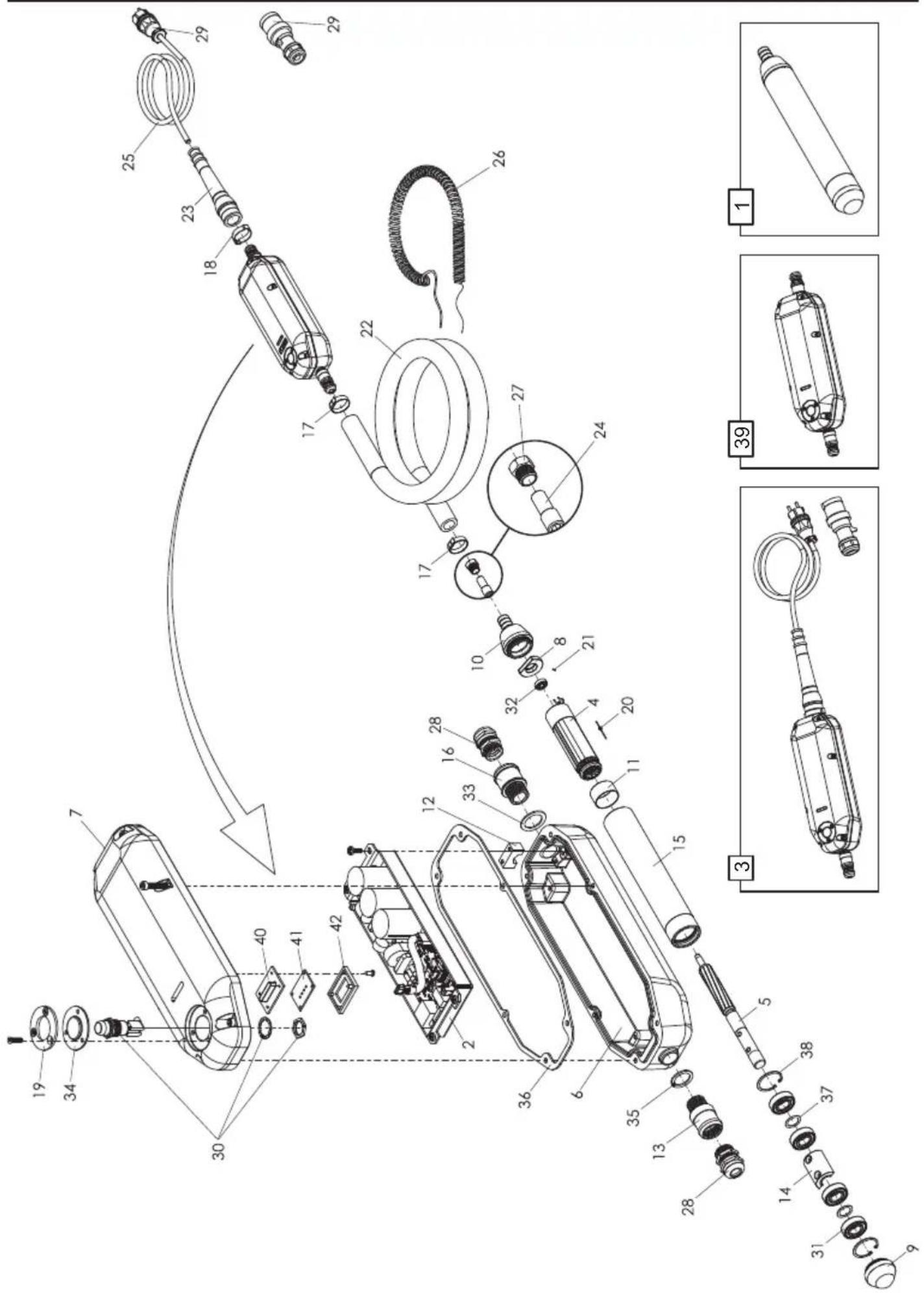
text_image
Exploded view diagram of a mechanical device with numbered parts and exploded viewsVibratech+ High Frequency Converter
| Item 38 42 52 58 Description Qty | ||||||
| 1 | 972/99700 | 972/99701 | 972/99702 | 972/99703 | Poker Head - 230v (cw Thermal) | 1 |
| 1 | 972/99706 | 972/99707 | 972/99708 | 972/99709 | Poker Head - 110v (cw Thermal) | 1 |
| 1 | N/A | N/A | 972/99704 | 972/99705 | Poker Head - 230v (cw Rubber Cap & Thermal) | 1 |
| 1 | N/A | N/A | 972/99710 | 972/99711 | Poker Head - 110v (cw Rubber Cap & Thermal) | 1 |
| 2 | 972/99712 | 972/99712 | 972/99712 | 972/99712 | Electronic Plate & Bracket - 230v | 1 |
| 2 | 972/99713 | 972/99713 | 972/99713 | 972/99713 | Electronic Plate & Bracket - 110v | 1 |
| 3 | 972/99714 | 972/99715 | 972/99715 | 972/99715 | Converte Set - 230v | 1 |
| 3 | 972/99716 | 972/99717 | 972/99717 | 972/99717 | Converte Set - 110v | 1 |
| 4 | 972/99718 | 972/99718 | 972/99719 | 972/99720 | Stator Assembly - 230v | 1 |
| 4 | 972/99721 | 972/99721 | 972/99722 | 972/99723 | Stator Assembly - 110v | 1 |
| 5 | 972/99724 | 972/99725 | 245/99611 | 245/99587 | Rotor Assembly | 1 |
| 6 | 972/99840 | 972/99840 | 972/99840 | 972/99840 | Switch Housing | 1 |
| 7 | 972/99726 | 972/99726 | 972/99726 | 972/99726 | Switch Housing Cover - 230v | 1 |
| 7 | 972/99727 | 972/99727 | 972/99727 | 972/99727 | Switch Housing Cover - 110v | 1 |
| 8 | 245/99518 | 245/99518 | 972/99728 | B-245/99517 | Bearing Support | 1 |
| 9 | 245/99537 | 244/99550 | 245/99583 | 245/99582 | Cylinder Tap Nut | 1 |
| 9 | N/A | N/A | 245/99540 | 245/99541 | Cylinder Tap Nut (cw Rubber Cap | 1 |
| 10 | 245/99536 | 245/99535 | 972/99729 | 245/99527 | Link Hose Nut | 1 |
| 11 | 245/99539 | 245/99539 | 972/99730 | 245/99528 | Distance Collar | 1 |
| 12 | 972/99731 | 972/99731 | 972/99731 | 972/99731 | Clamp Fixing Cable Connection | 1 |
| 13 | 972/99842 | 972/99843 | 972/99843 | 972/99843 | Poker Head Connector | 1 |
| 14 | 972/99844 | 972/99732 | 972/99845 | 245/99588 | Eccentric | 1 |
| 15 | 972/99733 | 972/99734 | 245/99612 | 245/99589 | Cylinder Motor Housing | 1 |
| 16 | 972/99847 | 972/99847 | 972/99847 | 972/99847 | Flex Hose Connector | 1 |
| 17 | 245/99544 | 245/99545 | 245/99545 | 245/99545 | Hose Clamp | 2 |
| 18 | 972/99848 | 972/99848 | 972/99848 | 972/99848 | Sleeve Clamp | 1 |
| 19 | 972/99735 | 972/99735 | 972/99735 | 972/99735 | Flat Washer | 1 |
| 20 | 245/99546 | 245/99546 | 245/99546 | 245/99546 | Stator Cylinder Pin | 1 |
| 21 | 245/99547 | 245/99547 | 245/99549 | 245/99548 | Bearing Support Pin | 1 |
| 22 | 972/99850 | 972/99851 | 972/99851 | 972/99851 | Rubber Hose - 7m | 1 |
| 22 | 972/99873 | 972/99874 | 972/99874 | 972/99874 | Rubber Hose - 10m | 1 |
| 23 | 972/99852 | 972/99852 | 972/99852 | 972/99852 | Rubber Sleeve | 1 |
| 24 | 972/99736 | 972/99853 | 972/99853 | 972/99853 | Connector | 1 |
| 25 | 972/99855 | 972/99855 | 972/99855 | 972/99855 | Connection Cable | 1 |
| 26 | 972/99737 | 972/99739 | 972/99739 | 972/99739 | Interior Connection Cable - 7M | 1 |
| 26 | 972/99738 | 972/99740 | 972/99740 | 972/99740 | Interior Connection Cable - 10M | 1 |
| 27 | 972/99741 | 972/99857 | 972/99857 | 972/99857 | Nut Connector | 1 |
| 28 | 245/99558 | 245/99558 | 245/99558 | 245/99558 | Housing Connector | 2 |
| 29 | 972/99858 | 972/99858 | 972/99858 | 972/99858 | Schuko Plug - 230v | 1 |
| 29 | 244/99576 | 244/99576 | 244/99576 | 244/99576 | Schuko Plug - 110v | 1 |
| 30 | 972/99860 | 972/99860 | 972/99860 | 972/99860 | On / Off Button | 1 |
| 31 | 972/99861 | 244/99567 | 972/99862 | 972/99863 | Bearing | 3 |
| 32 | 245/99563 | 245/99563 | 245/99564 | 245/99564 | Bearing | 1 |
| 33 | 972/99865 | 972/99865 | 972/99865 | 972/99865 | Washer | 1 |
| 34 | 972/99742 | 972/99742 | 972/99742 | 972/99742 | On / Off Button Seal | 1 |
| 35 | 972/99867 | 972/99867 | 972/99867 | 972/99867 | Washer | 1 |
| 36 | 972/99868 972/99868 | 972/99868 | 972/99868 Housing Seal | 1 | ||
| 37 | 972/99743 | 245/99630 | 245/99570 | 245/99570 | Friction Washer | 2 |
| 38 | 245/99574 245/99633 245/99573 | 245/99575 Seeger Ring | 2 | |||
| 39 | 972/99744 972/99745 972/99745 | 972/99745 Converter - 230v | 1 | |||
| 39 | 972/99746 972/99747 972/99747 | 972/99747 Converter - 110v | 1 | |||
| 40 | 972/99748 972/99748 972/99748 | 972/99748 LED Circuit Seal | 1 | |||
| 41 | 972/99749 972/99749 972/99749 | 972/99749 LED Circuit | 1 | |||
| 42 | 972/99750 972/99750 972/99750 | 972/99750 LED Circuit Bracket | 1 | |||
| - | 244/99578 244/99578 244/99578 | 244/99578 300v Varistor - 230v | 1 | |||
| - | 244/99579 244/99579 244/99579 | 244/99579 175v Varistor - 110v | 1 | |||