PD 250/E - Metal Lathe PROXXON - Free user manual and instructions
Find the device manual for free PD 250/E PROXXON in PDF.
| Product type | Metal lathe |
| Brand | PROXXON |
| Model | PD 250/E |
| Distance between centers | 250 mm |
| Height of centers | 70 mm |
| Height above bed | 43 mm |
| Clamping capacity (internal jaws) | 2 – 27 mm (max. 75 mm) |
| Clamping capacity (external jaws) | 25 – 71 mm |
| Cross slide travel | 60 mm |
| Top slide travel | 45 mm |
| Rotational speed | 400 – 1600 rpm (adjustable by belt) |
| Automatic feed | 0.05 or 0.1 mm/rev (depending on gears) |
| Metric threading | Pitch: 0.5 ; 0.625 ; 0.7 ; 0.75 ; 0.8 ; 1.0 ; 1.25 ; 1.5 mm |
| Bed material | Ribbed grey cast iron with polished prismatic guides |
| Chuck | 3-jaw (standard capacity 35 mm, max 68 mm with reversed jaws) |
| Tailstock | Yes, with MK1 taper |
| Chuck guard | With automatic motor cut-off |
| Noise level | May exceed 85 dB(A) – wear hearing protection |
| Included accessories | Rotating tailstock center, tool holder, tool set, set of change gears, timing belt |
| Power supply | Mains (230 V ~ 50 Hz estimated) |
Frequently Asked Questions - PD 250/E PROXXON
User questions about PD 250/E PROXXON
0 question about this device. Answer the ones you know or ask your own.
Ask a new question about this device
Download the instructions for your Metal Lathe in PDF format for free! Find your manual PD 250/E - PROXXON and take your electronic device back in hand. On this page are published all the documents necessary for the use of your device. PD 250/E by PROXXON.
USER MANUAL PD 250/E PROXXON
natural_image
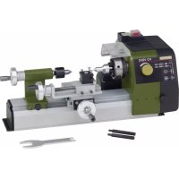
3D rendering of a Proxxon lathe machine with visible gears and housing (no text or symbols)Manual
Deutsch 6
Fold on the picture pages when reading the user instructions.
Français 26
natural_image
Mechanical device with labeled parts (1 and 2), no visible text or symbols beyond labelsFig. 2
natural_image
Mechanical assembly diagram showing a lathe machine with labeled parts (no text or symbols beyond labels)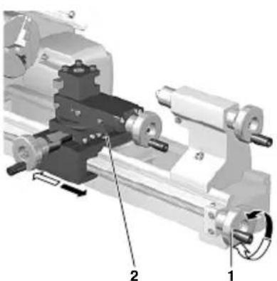
natural_image
Mechanical assembly diagram showing a lathe with two labeled parts (1 and 2), no readable text or symbols present.Fig. 4
natural_image
Mechanical assembly diagram showing a rotating component with labeled parts (no text or symbols present)Fig. 5
natural_image
Mechanical assembly diagram showing a lathe with labeled parts (0, 1) and no readable text or symbols beyond labelsFig. 6
text_image
1 2 35 4 Fig. 7Fig. 7
text_image
a f e d c bFig. 8
text_image
Technical diagram of a mechanical assembly with numbered components labeled 1, 2, and 3.Fig. 9
natural_image
Mechanical assembly diagram showing gears and shafts in a mechanical component (no text or symbols visible)Fig. 10
natural_image
Three abstract black-and-white line patterns with no text or symbolstext_image
L = 3 x D ΦD 1 2Fig. 12
natural_image
Two mechanical clamping components with numbered parts, no visible text or symbolsFig. 13
text_image
Technical diagram of a lathe machine with numbered components for identificationFig. 14
text_image
Technical diagram of a mechanical assembly with labeled parts 1 and 2, showing internal components and directional arrow.Fig. 15
text_image
Technical diagram of a mechanical assembly with labeled parts 1 and 2, showing components like gears and a central component.Fig. 16
text_image
Technical diagram of a mechanical assembly with numbered components labeled 1 to 4Fig. 17
text_image
Technical diagram of a mechanical assembly with numbered components labeled 1 to 5Fig. 18
text_image
W 2 Z₁/Z₂ 3 L 1 4Fig. 19
text_image
Technical diagram of a lathe machining setup with numbered components and an inset showing a detailed view of the machining process.Fig. 20
natural_image
Mechanical gear assembly diagram showing gears and shafts with numbered components (no text or labels visible)Fig. 21
natural_image
Mechanical assembly diagram showing a rotating disk and housing components (no text or labels visible)Fig. 22 Fig. 23
natural_image
Mechanical assembly diagram showing a rotating shaft and housing with numbered components (no text or symbols)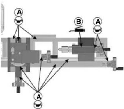
flowchart
graph TD
    A1["Component A"] --> A2["Component A"]
    A2 --> A3["Component A"]
    A3 --> B1["Component B"]
    B1 --> A4["Component A"]
    A4 --> B2["Component B"]
    B2 --> A5["Component A"]
    A5 --> B3["Component B"]
    B3 --> A6["Component A"]
    A6 --> B4["Component B"]
    B4 --> A7["Component A"]
    A7 --> B5["Component B"]
    B5 --> A8["Component A"]
    A8 --> B6["Component B"]
    B6 --> A9["Component A"]
    A9 --> B7["Component B"]
    B7 --> A10["Component A"]
Fig. 26
text_image
1 2 3 5 4Fig. 24
text_image
Technical diagram of a mechanical assembly with numbered components labeled 1, 2, 3, and 4Fig. 25
text_image
1 112 2Fig. 27
text_image
2 1 1 2Fig. 28
natural_image
3D mechanical assembly diagram showing two labeled components (1 and 2) with no visible text or symbolsFig. 29
• We chose In arment.
text_image
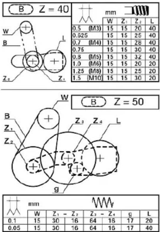
B Z = 40 W + B L Z₀ Z₁| mm | ||||
| W | Z_1 | Z_2 | L | |
| 0.5 (M3) | 15 | 15 | 20 | 40 |
| 0.625 | 15 | 15 | 25 | 40 |
| 0.7 (M4) | 15 | 15 | 28 | 40 |
| 0.75 | 15 | 15 | 30 | 40 |
| 0.8 (M5) | 15 | 15 | 32 | 40 |
| 1.0 (M6) | 15 | 15 | 20 | 20 |
| 1.25 (M8) | 15 | 15 | 25 | 20 |
| 1.5 (M10) | 15 | 15 | 30 | 20 |
text_image
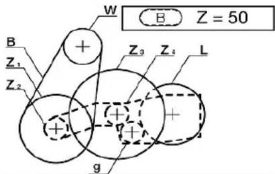
B Z = 50 W Z₁ Z₂ + Z₃ Z₄ L g| mm | |||||||
| W | Z_1 - Z_2 | Z_3 - Z_4 | g | L | |||
| 0.1 | 15 | 30 | 16 | 64 | 16 | 17 | 20 |
| 0.05 | 15 | 30 | 16 | 64 | 16 | 17 | 40 |
Stehlünette (No. 24010)
Translation of the Original Operating Instructions
Foreword
Dear Customer,
By purchasing your PROXXON Lathe PD 250/E, you have chosen a good-quality, high-grade machine. The latest production and testing methods guarantee a high level of reliability for this machine.
This instruction manual covers:
- safety regulations
- o peration and maintenance
• s pare p arts list
Please read carefully!
Using this instruction manual will
- make it easier for you to get used to the machine,
- help prevent faults occurring due to improper use and
- increase the service life of your machine.
Keep this instruction manual in an easily accessible place.
Only operate this machine if you are qualified to do so and follow the guidelines in this instruction manual.
PROXXON does not accept responsibility for the safe functioning of the machine
- if it is handled in a manner which constitutes improper use,
- if it is used for other purposes which are not specified in the instruction manual,
• if the safety regulations are not observed.
Warranty claims are invalid if
• t he machine is incorrectly operated,
- t he machine has not been sufficiently maintained.
In the interests of your safety, p lease always observe the safety regulations.
Only use genuine PROXXON spare p arts.
We reserve the right to make further alterations for the purpose of technical progress.
We wish you every success with your machine.
PROXXON GmbH
Safety guidelines:
Avoid untidiness in your working area.
An untidy working area always means an increased accident risk. Remember that your working area needs to be cleaned of wood chips from time to time as well as during operation.
Fasten the device to a solid surface and make sure it is even.
Also, always make sure that the device cannot fall down or topple during operation. Drill holes in the base have been provided for this purpose so that the planer can be screwed down to the surface.
Check the device for signs of damage before each use.
Always check the cutting tools, the safety mechanisms, the connecting cable and the plug every time before you start up the planing machine.
Please note: Defective parts, particularly damaged safety mechanisms, may only be replaced by a specialist or the PROXXON customer service. Only use original Proxxon spare parts.
Do not manipulate your machine!
Do not make any changes to the machine and do not manipulate anything! Changes or manipulations could impair the mechanical and electrical safety, but your safety in particular would also be at risk due to electric shock and further adverse effects. Injuries and material damage could be the result.
Never work without the designated safety mechanisms.
Make sure in any event that the machine chuck guard is folded down while working and that the motor cutoff operates reliably when the chuck guard is lifted!
Pay attention to environmental effects!
Use the machine only in dry environments and never in the vicinity of combustible liquids or gases. Make sure you have good lighting!
Wear protective goggles!
Wear hearing protection!
The sound pressure level when working with the machine can exceed 85 dB (A), therefore always work with hearing protection!
Wear suitable working clothes!
When working, never wear loose clothing, such as neckties or scarves, as this could get caught in one of the moving parts or the automatically moving workpiece during operation and cause injuries. If you have long hair, wear a hairnet and remove your jewellery.
Do not use any damaged or deformed cutting tools.
Please make absolutely sure the cutting tools are in perfect condition. Visually check for this intact condition before each use!
Keep children and non-participants away from the working area.
Make sure that children and non-participants maintain an appropriate safety distance! Youths below the age of 16 may only use the machine under professional instruction and for purposes of schooling. When not in use, keep the machine out of the reach of children!
Do not overstress your tool.
Of course, you will only achieve optimal work results within the performance range for which the machine is designed! Therefore, avoid making the infeed too large! Do not misuse the machine, and do not use it for work for which it is not intended.
Always be prudent and attentive!
Observe the machine during work and proceed sensibly. Do not use the machine if you are distracted, tired, or if you have consumed alcohol.
Handle the connecting cable with care!
Protect the connecting cable from heat and sharp edges, and lay the cable so that it cannot be damaged. Do not pull on the cable to disconnect the plug from the socket outlet, and do not lift the device by the cable. Ensure cleanliness: Protect the cable from grease and oil!
Clean thoroughly after work!
Disconnect the mains plug!
Always unplug the mains plug when not in use, before maintenance, when changing tools, cleaning or repairing! Removing the chips is also a part of cleaning!
Carefully read the operating instructions before use and keep them in a safe place!
Contents
| Page | |
| Foreword | 1 |
| Safety guidelines 16 | |
| Legend 17 | |
| Description of the machine 18 | |
| Technical data | 18 |
| Installation and setting up | 18 |
| Operating the handwheels | 18 |
| Switching on the automatic feed | 1 |
| Working with the tailstock | 19 |
| Selecting the turning tool | 19 |
| Inserting the cutting tool in the tool post | |
| Setting the spindle speeds | 20 |
| Calculating the maximum spindle speed | 2 |
| Clamping the work piece in the lathe chuck | |
| Exchanging the clamping jaws | 20 |
| Switching on the machine | 20 |
| Longitudinal turning | 21 |
| Face turning | 21 |
| Taper turning | 21 |
| Cutting off a work piece | 2 |
| Machining long work pieces with tailstock and centre | |
| Fitting change gears for thread cutting | 2 |
| Thread cutting with the turning tool | 2 |
| Thread cutting using the top slide | 2 |
| Cutting left threads | 23 |
Accessories for Lathe PD 250/E 23
Installing the centre I athe 23
Removing the centre 23
Four-jaw chuck 23
Collet chuck unit and collet chucks 23
Fastening the drill chuck 24
Fixed steady 24
Repair and Maintenance 24
Cleaning 24
Adjusting the play of the guides 24
Adjusting the play of the handwheels 24
EC Declaration of Conformity 25
Spare p arts list 126
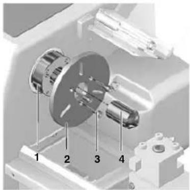
Legend (Fig.1)
- Main spindle
- Lathe chuck
- Turning tool holder
- Rotating centre
- Flange surface for milling unit
- Sleeve
- Clamp screw for sleeve 6
- Tailstock
- Sleeve adjusting handwheel
- Handwheel for leadscrew
- Clamp screw for tailstock
- Leadscrew
- Adjusting handwheel for top slide
- Top s lide
- Support
- Cross-slide
- Adjusting handwheel for cross-slide
- Clutch switch for automatic feed
- Drive gearbox cover with speed table
- Switch for anticlockwise rotation - stop - clockwise rotation
- Main switch
- Function display
- Control
24 Hollow hexagon wrench - Lathe chuck wrench
- Chuck guard
Description of the machine
The PROXON lathe PD 250/E is an extensible system which consists of
• solid shaft electronics for high torques over the entire speed range
• automatic feed
• lathe chuck and
- rotating centre
for machining steel, brass, aluminium and plastics.
It can also be used for face turning, longitudinal turning and thread cutting.
The machine is also suitable for boring, milling work and grooving by using the appropriate accessories.
The ribbed, grey cast iron machine bed with ground prismatic guideways ensures vibration-free work.
Technical data
| Centre distance | 250 mm |
| Centre height | 70 mm |
| Height above support | 43 mm |
| Holding capacity | |
| - Inner jaws | 2 - 27 mm, max. 75 mm |
| - Outer jaws | 25 - 71 mm |
| Cross-side adjustment | 60 mm |
| Top slide adjustment | 45 mm |
| Spindle passage | 10.5 mm |
| Nose support on chuck side | MK2 |
| Tool holder | 8x8 mm |
| Machine dimensions | 560x270x170 mm |
Always work with hearing protection!
We are safety glassed.

Installation and setting up
The standard equipment of the PROXION Lathe PD 250/E consists of the following parts:
- Metal working lathe complete with motor, automatic feed and triple jaw chuck including chuck key and chuck guard and accessories.
- rotating centre
• Stock kit
• change gear kit for thread turning
• tool holder
• Removable toothed belts.
The floor space must be even, vibration-free and stable. The machine must be fastened to a stable work bench using the bones provided.
Important
When lifting the machine, ensure that the plastic cover of the drive gearbox is closed. If it is not, the cap may break.
All naked metal parts are supplied in a corrosion protection preservative.
This preservative must be washed off with paraffin oil before using for the first time.
Subsequently oil all polished guides and spindles well. Fasten the chuck guard with screws.
Operating the handwheels
Important
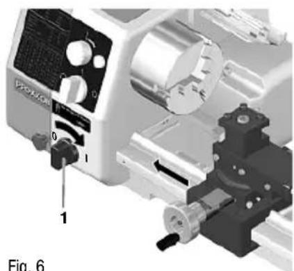
Switching on the automatic feed
Important
Only switch on the feed when the machine is stationary.
- Turn the switch 1 (Fig. 6) to the right.
- Turn the switch to the left to switch off the feed. If stiff, slightly move the handwheel of the leadscrew.
Important
When the automatic feed is switched on, always ensure that the support or turning tool do not collide with the lathe chuck or tailstock.
Note:
When the automatic feed is switched on, the support is pushed by 0.05 or 0.1 mm per turn depending on the gear combination
Please note the sticker on the inside of the drive gearbox when adjusting the feed.
The support always moves from right to left when the spindle is turning normally (clockwise rotation) and the automatic feed is switched on. This is also the normal feed when turning.
Of course, the support can also be moved back to the output position automatically.
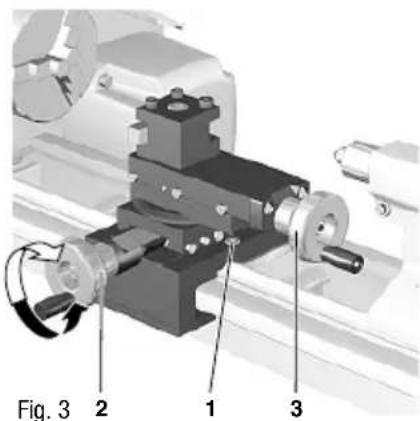
To do so, switch off the machine, slightly draw back the turning tool and then set the switch 2 (Fig. 2) to anticlockwise rotation.
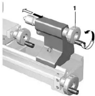
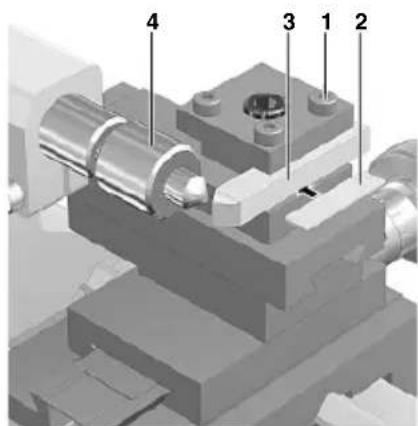
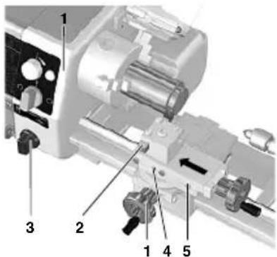
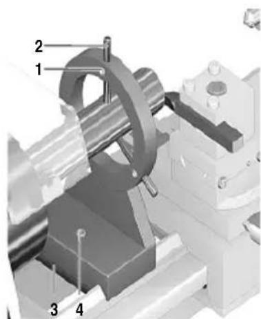
Working with the tailstock
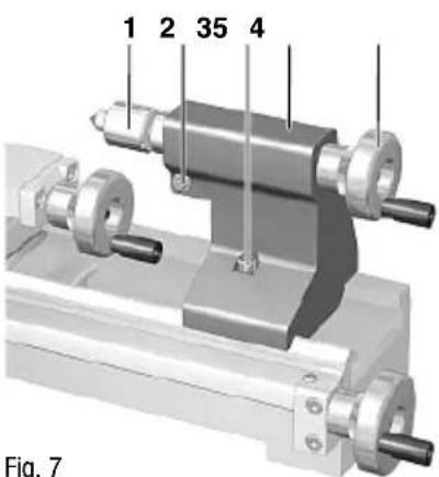
- Release the clamp screw 4 (Fig. 7), push the tailstock 2 on the guide into the required position and re-tighten the clamp screw.
Note:
A mount is located on the sleeve for the drill chuck or rotating centre with morse taper, size MK 1.
Important
Receiving tapers must always be perfectly clean.
Dirt, especially metal chips, affect the precision and can render the sleeve and shank taper unusable.
- To insert a tool, e.g. the centre 1 (Fig. 7), extend the sleeve approx. 10 mm by turning the handwheel 3.
- Firmly push the cone of the lathe center 1 (Fig. 7) by hand into the spindle sleeve. The cone is firmly seated and cannot be pulled out from the front.
- To release an inserted tool, turn handwheel 3 to the left to stop.
- Then turn approx. one further turn against the resistance. The taper is released and can be removed.
Note:
The sleeve can be clamped in any position by tightening the screw 5 (Fig. 7).
Selecting the turning tool
Important
For proper turning, it is essential that:
- the correct turning tool has been selected for the appropriate purpose
• the blade of the turning tool is sharp - the blade of the turning tool sits exactly in the "centre" position
• and is operated at the correct speed.
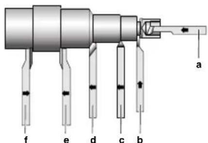
Inside turning tools (a) (Fig. 8)
• are used for interior diameter turning.
Cut-off tools (b)
• for plunge-cutting grooves and cutting off work pieces.
^1 Thread tools (c)
• are used for cutting outer threads.
- are used to achieve a clean surface when removing small chips.
Right side tools (e)
- is used to cut as many turning chips as possible in the right-hand direction of processing regardless of the quality of the work piece surface (so-called "rough-cutting").
Left side tools (f)
- are used to remove as many chips as possible in a short time when machining towards the left, regardless of the surface quality of the work piece.
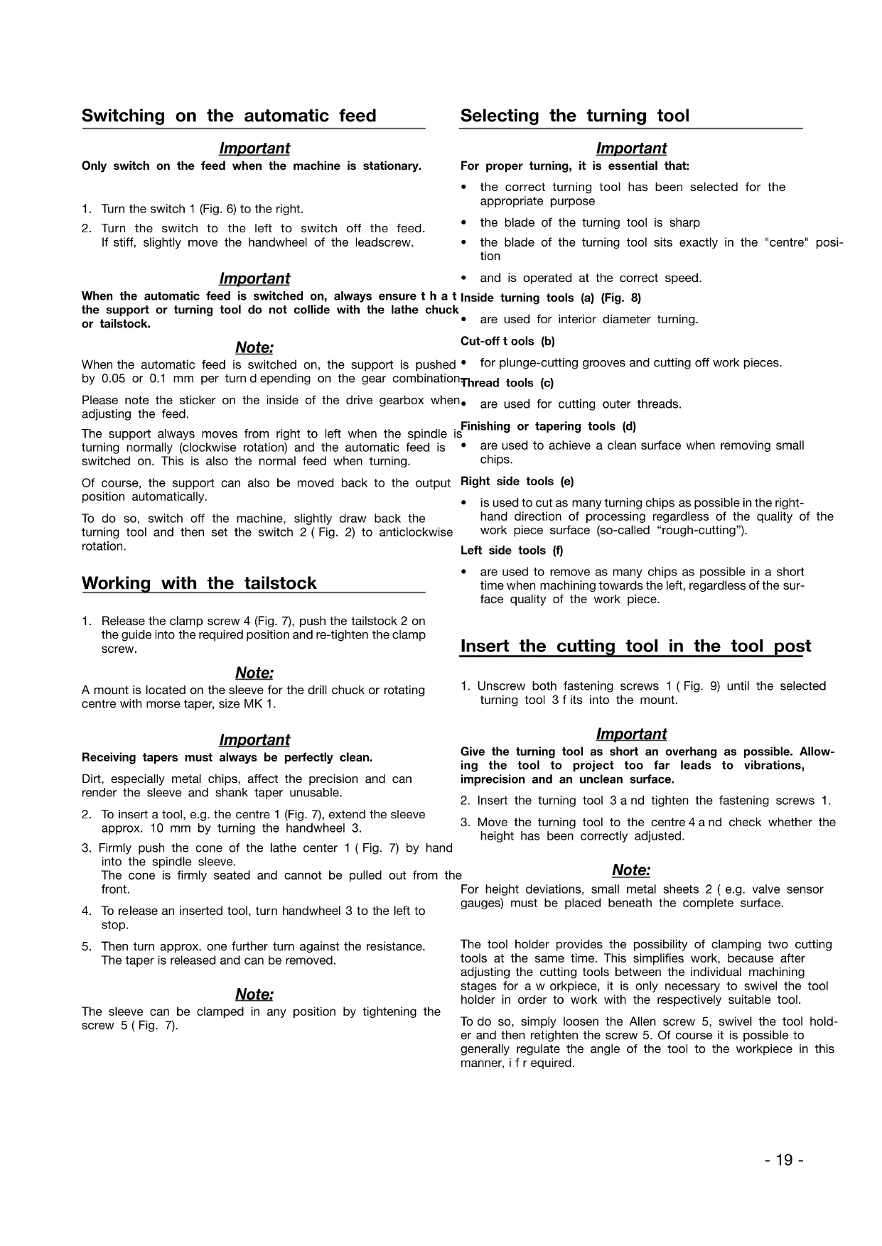
Insert the cutting tool in the tool post
- Unscrew both fastening screws 1 (Fig. 9) until the selected turning tool 3 fits into the mount.
Important
Give the turning tool as short an overhang as possible. Allowing the tool to project too far leads to vibrations, imprecision and an unclean surface.
-
Insert the turning tool 3 and tighten the fastening screws 1.
-
Move the turning tool to the centre 4 and check whether the height has been correctly adjusted.
Note:
For height deviations, small metal sheets 2 (e.g. valve sensor gauges) must be placed beneath the complete surface.
The tool holder provides the possibility of clamping two cutting tools at the same time. This simplifies work, because after adjusting the cutting tools between the individual machining stages for a workpiece, it is only necessary to swivel the tool holder in order to work with the respectively suitable tool.
To do so, simply loosen the Allen screw 5, swivel the tool holder and then retighten the screw 5. Of course it is possible to generally regulate the angle of the tool to the workpiece in this manner, if r required.
Do not leave the wrench in the lathe chuck. Risk of injury.
Important
Always disconnect the mains plug before working on the drive gearbox. Risk of injury.
The spindle speed must be adjusted to suit the work piece material and diameter.
Calculating the maximum spindle speed
The required spindle speed can be calculated when the specified maximum cutting speed for a certain material is known.
Maximum permissible spindle speed
$$ = \frac {\text { Cutting speed } x 1 0 0 0}{\text { Working piece diameter } x 3 . 1 4} $$
Example:
A work piece with a diameter of 20 mm is to be turned at a cutting speed of 50 rpm.
$$ \frac {5 0 \times 1 0 0 0}{2 0 \times 3 . 1 4} = 7 9 6 / \min $$
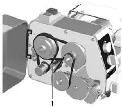
By shifting the V-belt (Fig. 10), set to the next highest speed. In this case, the speed is 1600 rpm. The correct speed is now set via the controls, and here is important to note that the controls cover a speed range of 25% to 100%, i.e. in our example, 400 rpm to 1600 rpm.
- Release the clamp screw from the drive gearbox and open the flap.
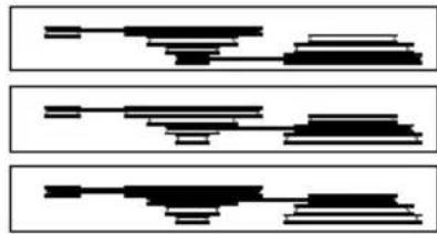
- Release V-belt tensioner 1 (Fig. 10).
- Adjust the relevant speed by shifting the V-belt according to Fig. 11.
- Re-tighten V-belt tensioner. Note the appropriate tension of the V-belt. Overtensioning increases the wear of the belt and bearing and reduces the motor power.
- Close the drive gearbox before commencing turning work.
Clamping the work piece in the lathe chuck
Important
If work pieces are c lamped in the lathe chuck using the tailstock without a steady, the projection (Fig. 12) must not be greater than three times the diameter of the material (L = 3 x D).
Note:
The normal lathe chuck has three steel jaws, which are u ni-formly adjusted and centre round work pieces automatically.
In the normal position, work pieces can be clamped up to a diameter of 35 mm. After turning the jaws, it is possible to clamp up to a diameter of 68 mm.
-
Turn the lathe chuck 2 (Fig. 12) using the wrench 1 until the work piece fits in the mount.
-
Clamp the work piece tightly and remove the wrench from the chuck.
- Check the running of the work piece and correct if necessary.
Important
Clamping a longer work piece which has been guided through the spindle and is projecting to the left increases the risk of injury. In this case, be particularly careful to ensure that no objects are caught in the rotating shaft. Protect this zone separately by fuse.
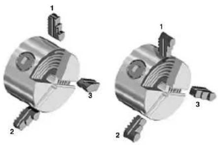
Exchanging the clamping jaws (Fig. 13)
Important
Remove mains plug.
Important
Do not clamp work pieces with a diameter greater than 68 mm. The clamping force of the jaws is then too small and the work piece may become loose. Danger of accident.
In order to clamp work pieces externally (e.g. for clamping solid steel bars with greater diameters, the included outside jaws must be inserted into the chuck instead of the factory-mounted inside jaws.
STo reverse or exchange the jaws, please proceed as follows:
- Disconnect the mains plug to prevent the machine from starting up unintentionally.
- Use the chuck key to screw out the jaws as far as possible so that they can be removed from the chuck.
- Reverse or exchange the jaws and reinsert. During the procedure, please pay attention to the identification: Numbers (1, 2, 3) have been imprinted on the jaws!
- Screw down the chuck with the chuck key and check the centricity of the jaws. If required, correct the position of the jaws by reinserting in the chuck body so that the jaws grip the spiral in the correct position.
- If you want to work with the inside jaw chuck again, repeat the steps described above in the reverse order, i.e. first insert jaw nos. 1 and 2, and then 3.
Switching on the machine
Important
Before switching on the machine, ensure that the jaw chuck wrench is not in the chuck, the jaws are not protruding and that there is no-one in the danger zone.
Activation of the machine while clamping pins are in the chuck holes can fling these out or lead to jamming during starting. Danger: Serious injuries or material damage may result as a consequence of this!
Only switch on the machine when the part to be turned is clamped in the chuck, as otherwise the jaws could become loose and cause injury.
Caution:
Always work within the intended performance range! Avoid spindle blockages caused by overloading. In the event of the
spindle blocking during operation, please switch off the machine immediately and configure the feed and infeed for further machining to avoid overloading of the machine.
Caution!
Before inserting the mains plug, please check if the information on the rating plate matches the local conditions of your mains supply. If they do not match, then damage or hazards during work could be result!
Caution!
Always wear hearing protection and protective goggles while working!
Caution!
Avoid abnormal body posture! Make sure you stand securely and can keep your balance.
Caution!
Please comply with the following when commissioning and working with the PD 250/E: Your machine is equipped with an automatic safety shutdown and can only be operated when the chuck guard is folded down! As soon as the chuck guard is folded up during operation, the motor will shut off a automatically! Only work with a folded down chuck guard! If the guard is defective, the machine may no longer be operated!
Avoid unnatural body positions. Ensure that you are standing in a safe position and keep your balance.
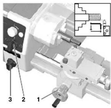
- Set selection switch 2 (Fig. 2) to "0" position.
- Switch on main switch 1. The function display should now illuminate.
- Turn the selection switch 2 to the right for normal turning.
- Turn the selection switch to the left for anti-clockwise rotation.
Important
Only switch on when the machine is stationary.
- When you have finished working, switch off the machine again using the main switch. Only then is the machine completely disconnected from the mains.
Longitudinal turning
Note:
Turning parallel to the rotational axis and machining cylindrical objects are the main uses of a lathe.
- Select the spindle speed according to the table on your lathe.
- Adjust the required speed by shifting the belt in the drive gearbox (see previous section).
- Clamp a right side tool 2 (Fig. 14) in the tool holder (see previous section).
- Switch off the automatic feed 3.
- Move the support from the right to the left of the work
- Adjust the cutting depth using the cross-slide 1.
Important
Before switching on the machine, manually check whether the spindle, chuck and work piece are running free. Do not allow the support or turning tool to collide with the lathe chuck.
- Switch on the machine (clockwise rotation).
- Manually feed or switch on the automatic feed 3, do not overload the machine.
Note:
If the top slide is not necessary, it is advisable to clamp it with the screw 4 (Fig. 14). The turning performance is improved by eliminating play.
Face turning
Note:
This method of working is used to turn off the face of a work piece.
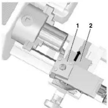
- Adjust the right side tool by approx. 2^ to 3^ (Fig. 15).
- Move the cross-slide from outside inwards (to the centre) with the turning tool.
Important
The cutting speed from outside inwards differs considerably for work pieces with larger diameters. Therefore, push the cross-slide slowly and sensitively.
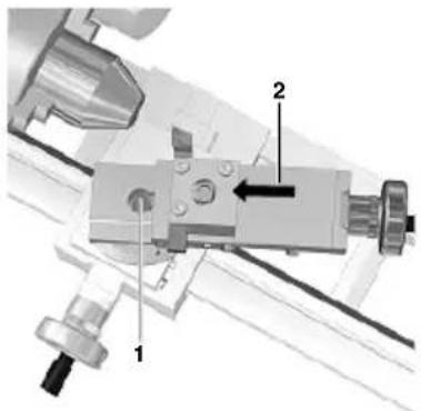
Taper turning
The top slide (Fig. 16) is equipped with a scale and can be swivelled by 45^ on either side of zero for taper turning. To do so, release fastening screw 1, adjust top slide and then re-tighten.
Cutting off a work piece
- Clamp the cut-off tool at right angles in the tool holder.
Important
Give the cut-off tool as short an overhang as possible (half of the diameter of the work piece + 1 mm). Similarly, give the work piece as short an overhang as possible.
Note the exact centre height of the cut-off tool. Work at low speeds and cool blade as often as possible.
- Sensitively move the cross-slide from outside inwards (to the centre) with the turning tool.
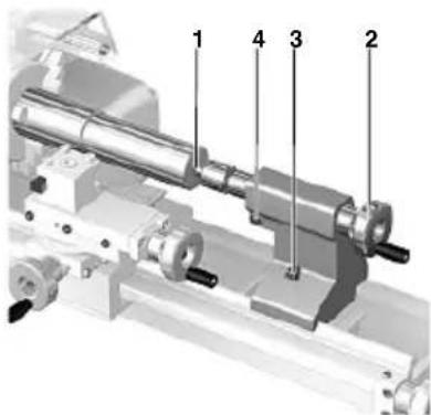
Machining longer work pieces with tail-stock and centre
Important
If the chuck projection is greater than three times the diameter of the work piece, the work piece must be held at the right end by the tailstock and centre.
For this purpose, a centre bore must be drilled on the right side of the work piece.
- Face turn the right face.
-
Insert the drill chuck (accessories) in the tailstock and clamp the centring drill.
-
Move the tailstock with drill chuck and centring drill up to the face of the work piece.
- Switch on the machine and drill centre bore using the sleeve feed.
- Replace the drill chuck with the rotating centre 1 (Fig. 17).
- Insert the centre in the centre bore and clamp the tailstock 3 s eecurely.
- Advance the sleeve 2 u ntil all play is eliminated.
- Secure the sleeve using a set screw 4.
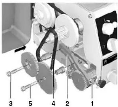
Fitting change gears for thread cutting
Note:
The PROXXON Lathe PD 250/E can be used to cut metric threads with a pitch of: 0.5 (M3), 0.625, 0.7 (M4), 0.75, 0.8 (M5), 1.0 (M6), 1.25 (M8), and 1.5 (M10).
The PD 250/E is supplied with installed gear arm and the change gear combination for the automatic feed of 0.05 mm/revolution. It is only necessary to replace the change gears installed on the gear arm for thread cutting.
- Release the clamp screw 1 (Fig. 18) and tilt the gear arm 2 slightly upwards to remove the toothed belt 4.
- Remove the fastening screws 3 and 5 from the normal gears for the automatic feed.
Note:
The number of teeth is imprinted on all change gears.
For example, if cutting a thread with a pitch of 1.0 mm, the table on the drive gearbox will show the following data:
text_image
B Z = 40 mm W Z1 Z2 L 0.5 (M3) 15 15 20 40 0.625 15 15 25 40 0.7 (M4) 15 15 28 40 0.75 15 15 30 40 0.8 (M5) 15 15 32 40 1.0 (M6) 15 15 20 20 1.25 (M8) 15 15 25 20 1.5 (M10) 15 15 30 20 B Z = 50 W Z1 Z2 L Z3 Z4 L g mm W Z1 - Z2 Z3 - Z4 g L 0.1 15 30 16 64 16 17 20 0.05 15 30 16 64 16 17 40W 15 - gear on the main spindle with 15 teeth. This gear is already installed on the shaft and must not be replaced.
Z_1 15 - Z_2 20 - Intermediate gear for the toothed belt of the main spindle with 15 teeth and permanently linked gear for the leadscrew with 20 teeth.
L20 - I eadscrew gear with 20 teeth.
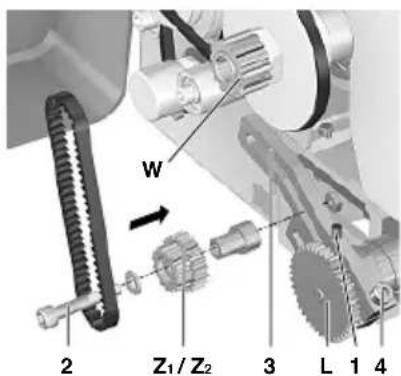
- Fasten the change gear "1ZZ2" with 15/20 teeth (Fig. 19) to the gear arm 3 using the screw 2, pulley, reduction sleeve and nut.
Note:
Do not yet tighten the fastening screw nut 2 (off-centre adjustment must still be possible).
The change gear "ZZ2" runs freely between pulley and sleeve.
The washer prevents the toothed belt from becoming detached from the gear "Z.
- Release the set screw 1, remove the change gear "L40" and replace with the change gear "L20".
Note:
The grain of the leadscrew change "L" must always point to the lathe chuck.
The set screw 1 must be clamped onto the flattened part of the shaft.
Important
To ensure that there is sufficient play between the change gears, always insert a s trip of newspaper between the teeth when pushing the change gears together. The thickness of the newspaper should correspond to the required tooth play.
- Push the axle of the change gear "1Z2" onto the arm so that it contacts the leadscrew gear "L" and then tighten the fastening screw nut 2.
- Position the short toothed belt for the connection between the gears "W" and "Z on the main spindles.
- Push the gear arm 3 downwards and tighten the clamp screw 4.
Thread cutting with the turning tool
Note:
For the following operations, the work piece must be machined completely and have the correct thread outer diameter. It is advisable to work out a c hamfer at the beginning of the thread. The thread turning tool must be clamped at an angle of 90° exactly.
- Clamp the work piece.
- Switch off the automatic feed and set the turning tool to the starting position.
Important
Use the lowest speed when cutting threads and proceed with utmost caution.
- Press button 2 (Fig. 20) to switch on the machine (clockwise rotation).
- Advance the turning tool on the cross-slide 1 and engage feed 3.
- Switch off the machine when the required thread length has been reached 2.
Important
The automatic feed must remain switched on until completion of the thread. Disengaging between individual steps renders further work impossible.
Only switch over the motor switch once the lathe chuck has come to a complete standstill. Switching over immediately increases wear and reduces the service life of the motor.
- Move back the turning tool slightly with the cross-slide.
- Move the support back to the output position. To do so, switch over the turning direction of the main spindle.
-
Advance the turning tool and repeat the steps described above until the required thread depth is reached.
-
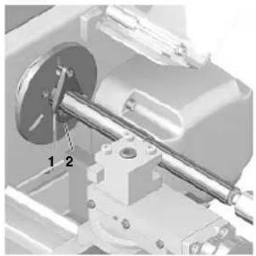
Insert the centre 4 (Fig. 22) in the fit 1 of the main spindle.
- Fit the driving disc 2 and fasten with three screws 3.
- On the left side, insert driving pin in one of the three long holes on the driving disc and the centre in the centre bore.
- Push the lathe carrier 1 (Fig. 23) onto the work piece (driving pin outwards) and tighten the fastening screw 2.
- On the right side, attach the work piece using the tailstock and fixed or rotating centre.
Important
When using a centre fixed to the tailstock, regular lubrication of the centre and centre bore is necessary to prevent the temper from loosening.
Thread cutting using the top slide
A perfect, good-quality thread can only be cut by using the top8. Guide a suitable aluminium or brass rod through the main slide. spindle from left to right.
Advancing the thread tool is performed using the cross-slide as 9. Hold the centre and release by lightly tapping the rod. described above.
However, t his causes the top slide to shift by 0.025 mm to the left and the same distance to the right.
The chip in the thread is therefore always only removed from one side.
Once the full thread depth has been reached, a final full cut is made by advancing slightly.
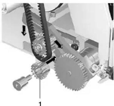
Cutting left threads
To cut left threads, the intermediate gear 1 (Fig. 21) must be installed between "Z-Z" and the leadscrew gear "L1".
In doing so, the turning direction of the leadscrew is reversed. The support runs from right to left when the chuck is turning clockwise.
Installation and operation are a s d described above.
Accessories for Lathe PD 250/E
Note:
The following accessories are not included in the standard equipment.
Installing the centre I athe (No. 24014)
Note:
Longer work pieces are c lamped between the brad points of the main spindle and tailstock.
The work piece must have a centre bore on both faces.
An exact cylindrical work piece is only achieved if the points align in the horizontal position.
- Remove three fastening screws from the three-jaw chuck and remove chuck.
- Thoroughly clean the fit for the driving disc and centre and its fit in the main spindle.
Removing the centre
- Guide a suitable aluminium or brass rod through the main spindle from left to right.
- Hold the centre and release by lightly tapping the rod.
Four-jaw chuck (No. 24036)
Note:
Round, oval, square and irregularly shaped work pieces can be clamped as it is possible to adjust the jaws individually.
Centric or eccentric clamping is possible.
Unlike the three-jaw chuck, centring of the work piece must be performed manually.
Important
Remove mains plug.
- Detach the three-jaw chuck and attach the four-jaw chuck.
- Open the four jaws, clean the contact faces and clamp the work piece lightly according to visual estimation.
- Move the support and turning tool onto the plane surface of the work piece.
- Turn the chuck by hand to establish symmetrical deviations.
- Adjust by opening one of the jaws and re-set the opposite jaw accordingly.
- Tighten all four jaws evenly, a lternating crosswise.
Important
In the normal clamping jaw position, only work pieces with an edge of up to max. 30 mm long can be clamped. The maximum length is 80 mm in the reverse position.
Larger work pieces are not securely held. Danger of accident.
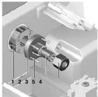
Collet chuck unit and collet chucks (No. 24038)
Note:
The collet chuck unit is especially suitable for processing round parts with great precision. The truth of running is
considerably greater than when working with a jaw chuck.
Important
Remove mains plug.
- Remove three fastening screws from the three-jaw chuck and remove chuck.
- Thoroughly clean the fit for the collet chuck mount 2 (Fig. 24) and the fit in the main spindle 1.
- Attach the collet chuck mount 2 u sing four fastening screws
Important
Always use the correct collet chuck to suit the work piece. Chucks with an oversized diameter are destroyed.
- Insert the collet chuck 6 and loosely screw in the union nut
Important
Never tighten the union nut when there is no work piece inserted.
- Insert the appropriate work piece in the collet chuck and tighten the union nut 5 u sing the tool pins 4.
Fastening the drill chuck (No. 24020)
- Remove the rotating centre from the sleeve. Thoroughly clean the grease and dirt from the shank taper and chuck bore.
- Insert the journal in the sleeve and firmly push onto the drill chuck.
Note:
Releasing the drill chuck is performed in the same way as the rotating centre.
Fixed steady (No. 24010)
The steady is particularly suitable for hollowing out long work pieces with diameters up to 40 mm.
- Release the fastening screw 4 (Fig. 25) and position retaining plate 3 c rosswise.
- Place the steady on the bed guide and set to the required position.
- Swivel the retaining plate 3 parallel to the steady base and tighten fastening screw 4.
- Release all clamp screws 1 and drive the individual retaining jaws 2 onto the work piece
Important
The jaws 2 must only touch the work piece and must not jam. Otherwise there is a risk of the work piece surface becoming scratched and the motor becoming overloaded.
If the work piece is not round and smooth at the support point, it must first be turned round.
Lubricate the jaws and work piece regularly when turning.
- Check that the work piece is positioned in the steady free of play and re-tighten clamp screws 1.
Repair and Maintenance
Cleaning
Caution!
Always disconnect the mains plug for all adjustment and maintenance work! Risk of serious injuries or damage due to inadvertent starting up of the device, or hazard due to electric shock!
- After use, thoroughly clean all chips from the machine using a brush or handbrush. Do not use compressed air for cleaning.
- Regularly lubricate or oil all moving parts, spindles and guides!
The outside of the housing can be cleaned with a soft, dry or damp cloth. It is possible to use mild soap or other suitable cleaning agent here. Solvents or cleaning agents containing alcohol (e.g. petrol, cleaning alcohol etc.) should be avoided, since these can attack the plastic housing casings as well as wash off the lubricants.
Please observe:
Changing the power supply cord may only be carried out by our Proxxon-Service-Department or a qualified specialist!
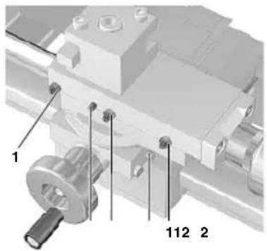
Adjusting the play of the guides (Fig. 27)
Note:
Even if the guides are regularly lubricated or oiled, it is unavoidable that the guides will exhibit play after some time due to wear.
The procedure described here using the example of the upper carriage is the same for all guides, therefore it applies analogously to the other guides on your lathe. For that reason they will not be treated separately here. Adjust the guides according to the motto: As "tightly" as necessary, as easy running as possible!
Please consider: If guides are set too closely, this causes higher operating forces as well as increased wear!
- Release and slightly unscrew the counter nuts 1 of the adjusting screws 2 for the upper carriage 3 using an open-end spanner 5.
- Evenly turn in the adjusting screws 2 with an Allen key 4 until the play is eliminated.
- Retighten the counter nuts 1. In the process, hold the adjusting screws 2 in position with the fixed spanner 5 so that they do not misadjust again.
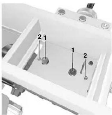
- Turn over the machine and slightly unscrew the set screw 2 (Fig. 28).
- Then check if the support can still be moved easily and if it runs completely without play.
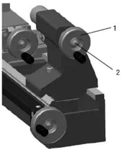
Adjusting the play of the handwheels (Fig. 29):
Just as for the guides, handwheel wear during operation cannot be avoided which ensures that the backlash increases slowly but consistently. To m inimise this again, please proceed as follows:
- Hold on to the handwheel 1 and release the cap nut 2.
- Turn the handwheel slightly to the right.
- Retighten the cap nut while still holding the handwheel.
Please consider here a s w ell:
The complete elimination of the backlash and a too "tight" adjustment for the handwheels is unreasonable: If the handwheels are set too closely, this causes higher operating forces as well as increased wear here a s well!
Disposal:
Please do not dispose of the device in domestic waste! The device contains valuable substances that can be recycled. If you have any questions about this, please contact your local waste management enterprise or other corresponding municipal facilities.
EC Declaration of Conformity
Name and address: PROXXON S.A. 6-10, Härebierg L-6868 Wecker
Product designation: PD 250/E Article No.: 24002
In sole responsibility, we declare that this product conforms to the following directives and normative documents:
EU EMC Directive 2014/30/EC DIN EN 55014-1 / 0 5.2012 DIN EN 55014-2 / 0 6.2009 DIN EN 61000-3-2 / 0 3.2015 DIN EN 61000-3-3 / 0 3.2014
EU Machinery Directive 2006/42/EC DIN EN 61029-1 / 0 1.2010
Date: 17.10.2016

PROXXON S.A. Machine Safety Department
The CE document authorized agent is identical with the signatory.

Lunette fixe (No. 24010)
Dipl.-ing. Jörg Wagner
PROXXON S.A.
Pevná luneta (No. 24010)
Sabit yatak (No. 24010)
text_image
Exploded view diagram of a mechanical assembly with numbered components and Chinese labelstext_image
Technical diagram of a mechanical assembly with numbered components and labeled partstext_image
Exploded view diagram of a mechanical assembly with numbered parts for identificationBaugruppe 03: Support
text_image
Exploded view diagram of a mechanical assembly with numbered parts for identificationAll PROXXON products are thoroughly inspected after production. Should a defect occur nevertheless, please contact the dealer from whom you purchased the product. Only the dealer is responsible for handling all legal warranty claims which refer exclusively to material and manufacturer error.
Improper use, such as capacity overload, damage due to outside influences and normal wear are excluded from the warranty.
You will find further notes regarding "Service and Spare Parts Management" at www.proxxon.com.