
272404 - Heating Hendi - Free user manual and instructions
Find the device manual for free 272404 Hendi in PDF.
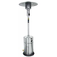
| Product type | Gas patio heater (outdoor heating) |
| Brand | Hendi |
| Model | 272404 |
| Intended use | Outdoors or very well ventilated rooms, professional use |
| Power supply | Butane or propane gas (depending on regulator) |
| Gas pressure (butane) | 50 mbar (remove the flame guard ring) |
| Recommended cylinder type | 9 kg gas cylinder (vertical position) |
| Total height (estimated) | Approximately 2.2 m |
| Weight (estimated) | Approximately 15 kg |
| Main materials | Steel (reflector, burner), glass (tube), metal protective grilles |
| Ignition | Piezoelectric impulse (AAA battery included) |
| Pilot light | Manual ignition with 10-second hold |
| Heat levels | LOW and HIGH, rotary selector |
| Safety | Safety thermocouple (automatic shut-off if pilot goes out), leak detection with soapy water |
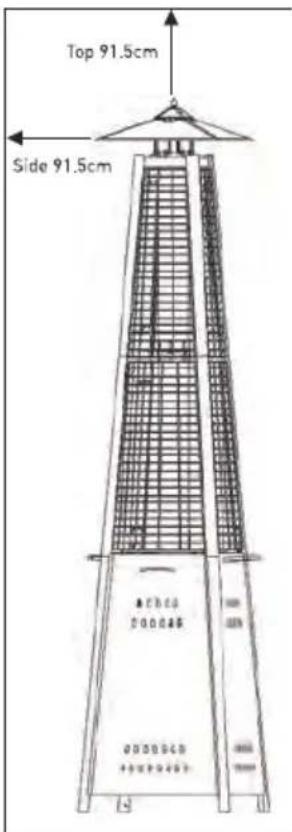
| Safety distance | Minimum 0.9 m from combustible materials |
| Assembly | Requires Phillips screwdriver, estimated time 45 minutes |
| Routine maintenance | Cleaning with warm soapy water, monthly check of hoses |
| Repairability | Spare parts available (reflector, burner, grilles, glass tube, thermocouple, etc.) |
| Warranty | 12 months (manufacturing defects) |
| Storage | Vertical, sheltered from weather, gas cylinder removed |
Frequently Asked Questions - 272404 Hendi
User questions about 272404 Hendi
0 question about this device. Answer the ones you know or ask your own.
Ask a new question about this device
Download the instructions for your Heating in PDF format for free! Find your manual 272404 - Hendi and take your electronic device back in hand. On this page are published all the documents necessary for the use of your device. 272404 by Hendi.
USER MANUAL 272404 Hendi
natural_image
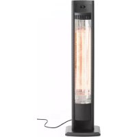
Exterior view of a tall outdoor café with a vertical glass panel and orange flame inside (no text or symbols visible)EN: You should read this user manual carefully before using the appliance.
EN: Keep these instructions with the appliance.
natural_image
Simple house icon with arrow pointing right, labeled 'OUTDOOR' below (no other text or symbols)EN: Use outdoors only.
Thank you for purchasing this Hendi appliance. Read this manual carefully, paying particular attention to the safety regulations outlined below, before installing and using this appliance for the first time.
Safety regulations
- This appliance must be used outdoors or in a well ventilated area, and should not be installed or used indoors.
- Change the gas cylinder in a well ventilated area, away from any inflammation sources.
- The cylinder must be stored outdoors or in a well ventilated area.
- Storage this appliance indoors is permissible only if gas cylinder is disconnected and removed from the appliance.
- Do not move this appliance when in operation, or after it has been turned off before the temperature has cooled down.
- Do not attempt to alter the appliance in any manner. Do not paint the radiant screen, control panel or reflector.
- Do not obstruct the ventilation holes of the cylinder housing.
- The appliance must be installed and gas cylinder stored in accordance with local gas fitting regulations.
- Shut off the valve at the gas cylinder or the regulator before moving the appliance.
- Use only the type of gas specified by the manufacturer.
• Repairs should be done by a qualified person.
- In case of violent wind, particular attention must be taken against tilting of the appliance.
- Check that the regulator seal is correctly fitted and able to fulfil its function.
- Close the gas supply at the valve of the gas cylinder or the regulator after use.
- Do not use this appliance until all connections have been leak tested.
- In the event of gas leakage, the appliance shall not be used or if alight, the gas supply shall be shut off and the appliance shall be investigated and rectified before it is used again.
- Checking the tubing or the flexible hose per month and each time the cylinder is changed.
- The tubing or the flexible hose must be changed within the prescribed intervals or with in one year. The flexible hose should not extended than 1.5m according to standard EN16436-1:2014+A3:2020.
- The hose assembly must be replaced prior to the appliance being put into operation if there is evidence of excessive abrasion or wear, or if the hose is damaged, and that the replacement hose assembly shall be that specified by the manufacturer.
- The heater should be inspected before use and at least annually by a qualified service person. More frequent cleaning may be required as necessary. It is imperative that control compartment, burners and circulating air passageways of the appliance be kept clean.
- Shut off and check heater immediately if any of the following conditions exist:
☐ The smell of gas in conjunction with extreme yellow tipping of the burner flames.
☐ Heater does not reach a proper temperature. A temperature less than 5^ C will cause restricted heat flow and the appliance will not work properly.
☐ The appliance starts making popping noises during use (a slight popping noise is normal when the appliance is extinguished).
- The regulator & hose assembly must be located out of pathways where people may trip over it or in area where the hose will not be subject to accidental damage.
- Any guard or other protective device removed for servicing the heater must be replaced before operating the heater.
- Children and adults should be warned of the hazards of high surface temperatures and should stay away to avoid burns or clothing ignition.
- Young children and pets should be carefully supervised when they are in the area of the heater.
- Clothing or other flammable materials should not be hung from the appliance, or placed on or near the appliance.
- Do not place articles on or against this appliance. Certain material or items when stored under or near this appliance will be subjected to radiant heat and could be seriously damaged.
- Do not use or store flammable materials near this appliance.
- Do not spray aerosols in the vicinity of this appliance while it is in operation.
• Always maintain at least 0.9m clearance from combustible materials. - Always position the appliance on a firm level surface. An amply ventilated area must have a minimum of 25% of the surface area open. The surface area is the sum of the walls surface.
- The injector in this appliance is not removable and the injector is only assembled by manufacture. This appliance is forbidden to convert from one gas pressure to another pressure.
- Do not connect the gas cylinder directly to the appliance without regulator.
- The gas cylinder must be fixed by cylinder belt, which is inside the housing, while installation.
Intended use
- The device is intended for professional use and can be operated only by qualified personnel.
- The appliance is designed only for heating outdoors or well ventilated areas. Any other use may lead to damage to the appliance or personal injury.
- Operating the appliance for any other purpose shall be deemed a misuse of the device. The user shall be solely liable for improper use of the device.
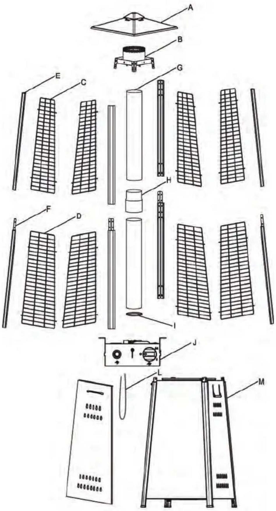
Patio heater part list
| PART # PART | NAME PICTURE QTY | ||
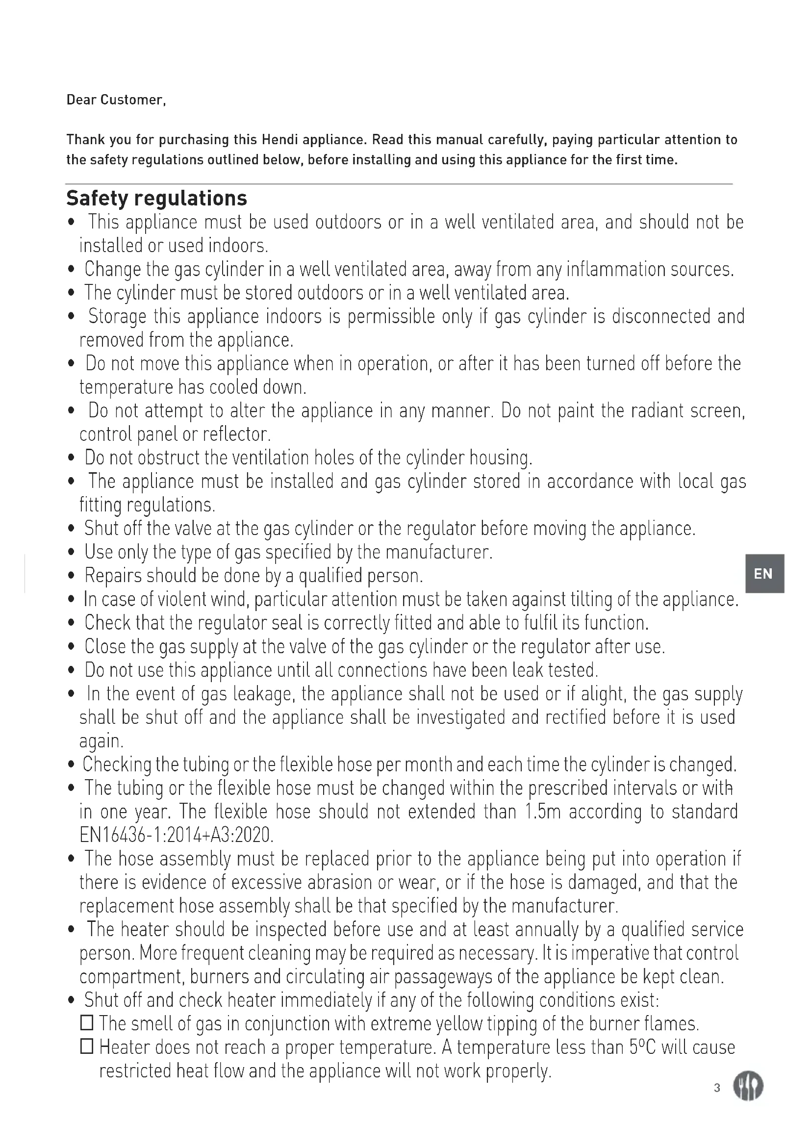
| A Reflector | 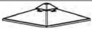 | 1 | |
| B Flame screen | 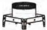 | 1 | |
| C Mesh guard - upper |  | 4 | |
| D Mesh guard - lower | 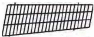 | 4 | |
| E Support bar - upper |  | 4 | |
| F Support bar - lower |  | 4 | |
| G Glass tube | 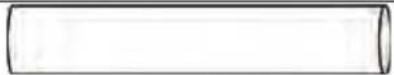 | 2 | |
| H Connection glass tube | 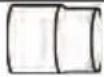 | 1 | |
| I Rubber ring | 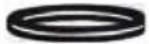 | 1 | |
| J Burner assembly |  | ||
| K Tank housing assembly | 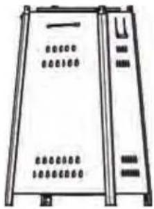 | 1 | |
| L Chain (assembled with door) | 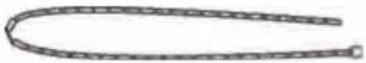 | 1 |
Hardware
| PART # PART | NAME PICTURE QTY DESCRIPTION | |||
| AA M6 cap nut | 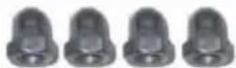 | 4 To connect | reflector and flame screen. | |
| BB | Standard screws & washer | 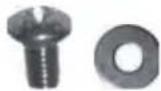 | 4 | M5 x 8 screw & M5 washer.To fix burner assembly on the tank housing assembly. |
Exploded view
Patio heater assembly
Assembly instructions
• List of Required Tools: Philip Screwdriver
- Leak Detection Solution one part detergent and three parts water
- Assemble all nuts and bolts loosely at first. Tighten all connections after completion of assembly. This eases your work and increase the stability of the appliance.
- Before assembly, make sure all packing material and any transmit protection must be removed.
- Small deviations in equipment may occur. This is no lack of quality but subject to improvements.
- If any part is missing or damaged, do not attempt to assembly this product, Contact customer service for replacement parts.
- Assembly should be performed on a flat, level, non-abrasive surface.
• ESTIMATED ASSEMBLY TIME: 45 minutes.
natural_image
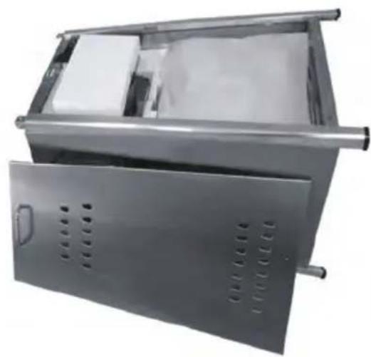
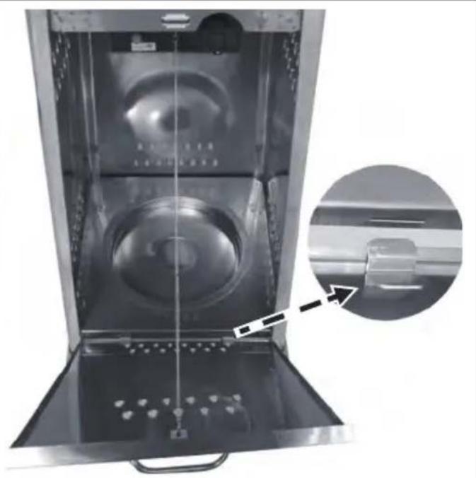
Exterior view of a stainless steel industrial storage unit with ventilation slots and metal frame (no text or symbols visible)STEP 1: Lie down tank housing assembly (K). Open door and take out all parts.
natural_image
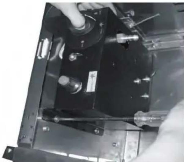
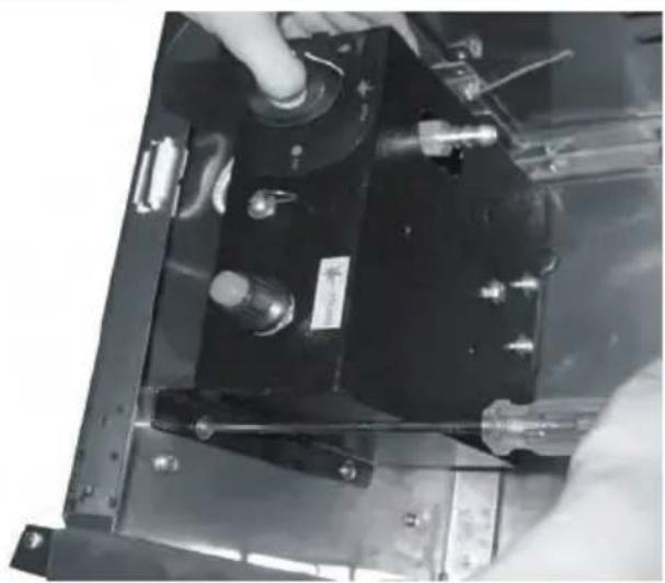
Close-up of a mechanical assembly with a hand adjusting a black component and a screwdriver inserted (no visible text or symbols)STEP 2: Keep tank housing in lie down position. Fix the burner assembly (J) to tank housing by using 4pcs Standard Screws and Washers (BB).

natural_image
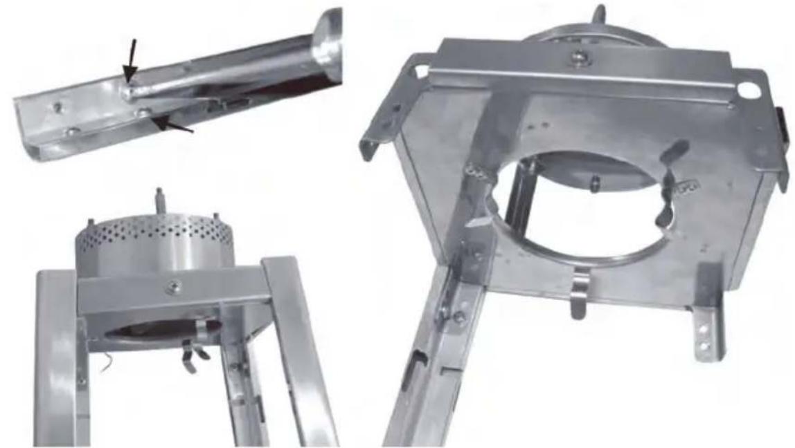
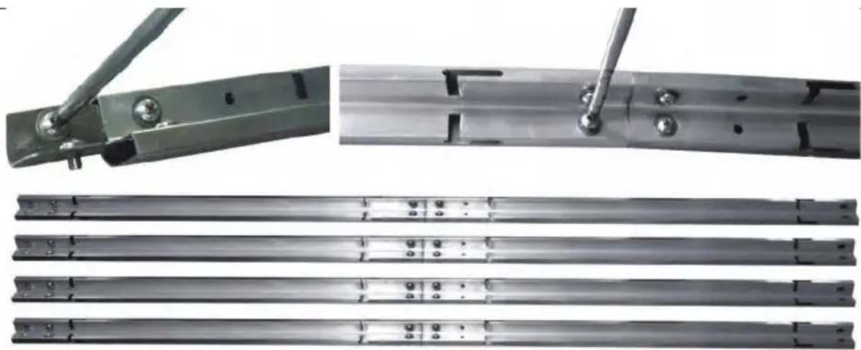
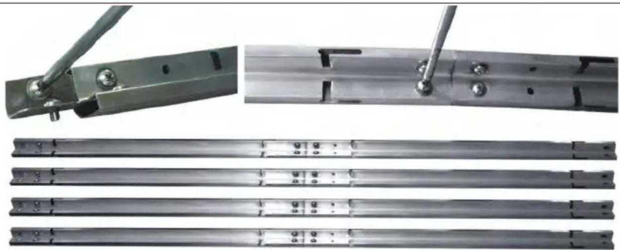
Technical illustrations of metal structural components with fasteners and mounting holes (no text or symbols visible)STEP 3: Unscrews 2pcs Standard screws and washers (BB) from a Support Bar - Lower (F). Insert Support Bar - Upper (E) to Support Bar - Lower (F) and fix by using 2pcs Standard screws and washers (BB). Repeat this step to connect left 3sets support bars.
natural_image
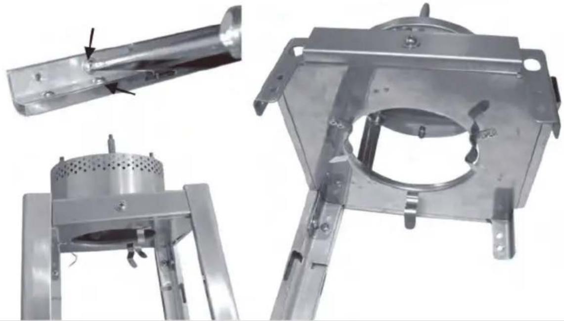
Three views of a metallic mechanical device with mounting brackets and a cylindrical opening (no text or symbols visible)STEP 4: Unscrewing 2pcs Standard Screws and Washers (BB) as arrow showed from Support Bar - UPPER (E). Attach Flame Screen (B) to the top of Whole Support Bar and fix by using 2pcs standard screws and washers. Repeat this step to connect Flame Screen (B) with left 3sets Whole Support Bar.
natural_image
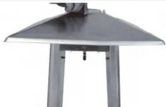
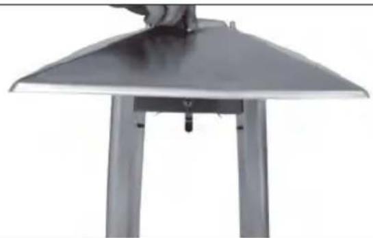
Metal umbrella-shaped table with a hand adjusting the top surface (no text or symbols visible)STEP 5: Place Reflector (A) on the Flame Screen (B) and fix by using 4pcs M6 CAP NUT (AA).
natural_image
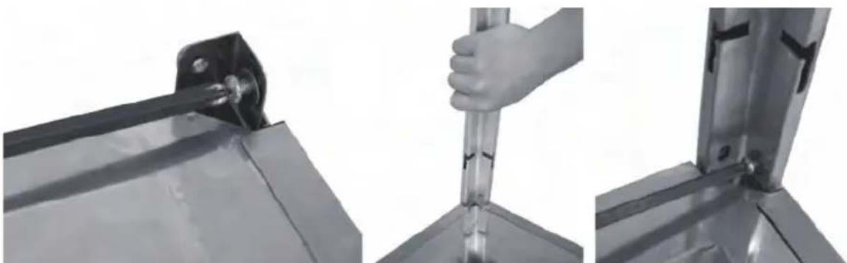
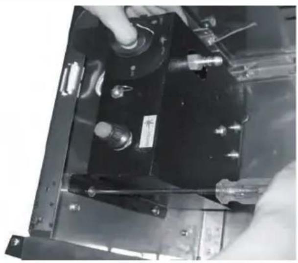
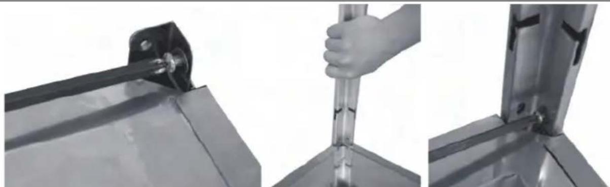
Three-panel image showing a hand holding a tool over a metal bracket, with no visible text or symbols.STEP 6: Unscrews 8pcs Standard Screws and Washers (BB) from top of tank housing assembly (K). Lift the assembled upper parts of heater and place them on the tank housing. Push support bar as photo showed and make sure each support bar inserts into slot. Fix at bottom position by using 8pcs standard screws and washers (BB).
natural_image
Close-up of a metal grid fence structure with two vertical supports and directional arrows indicating measurement or force points (no text or symbols)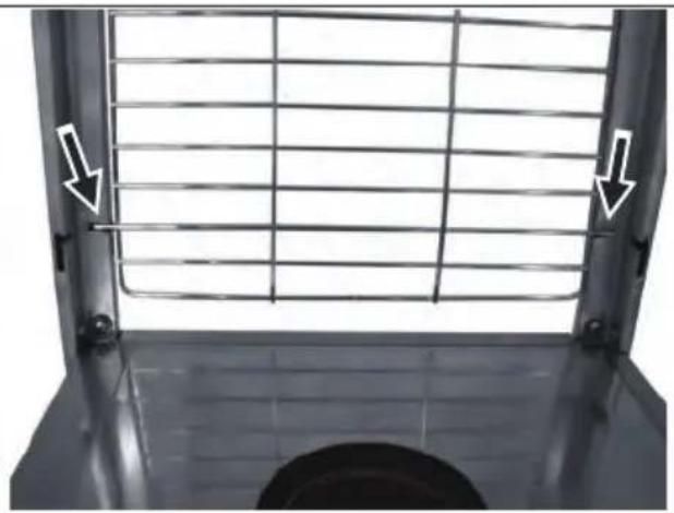
natural_image
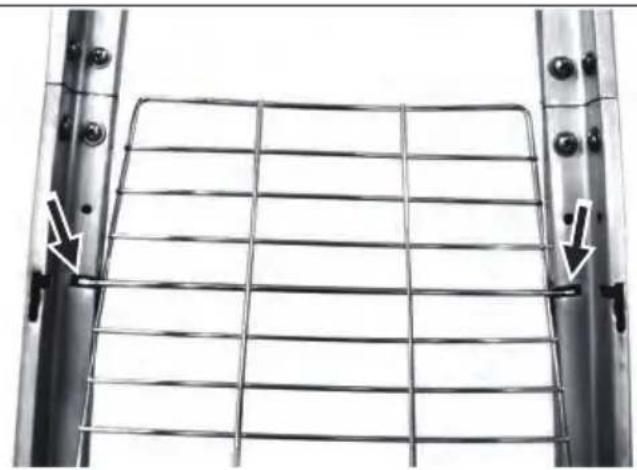
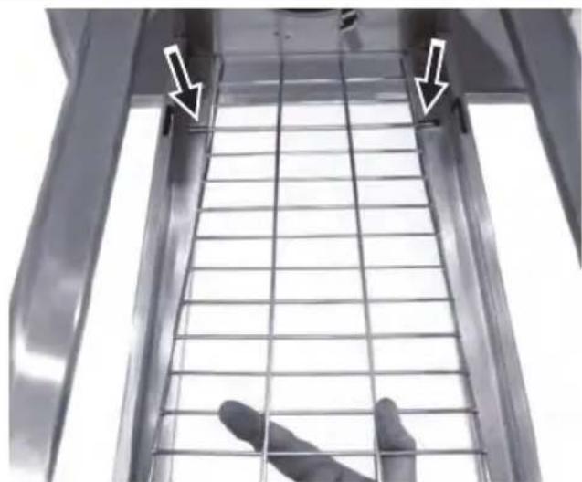
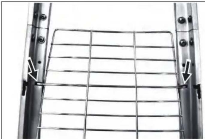
Metal grate with grid pattern and two white arrows pointing to the left side of a window (no text or symbols)STEP 7: Align and insert Mesh Guard - Lower (D) into the inside slots of Support Bar - Lower (F). Repeat this step to insert 2pcs Mesh Guard - Lower (D).
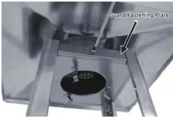
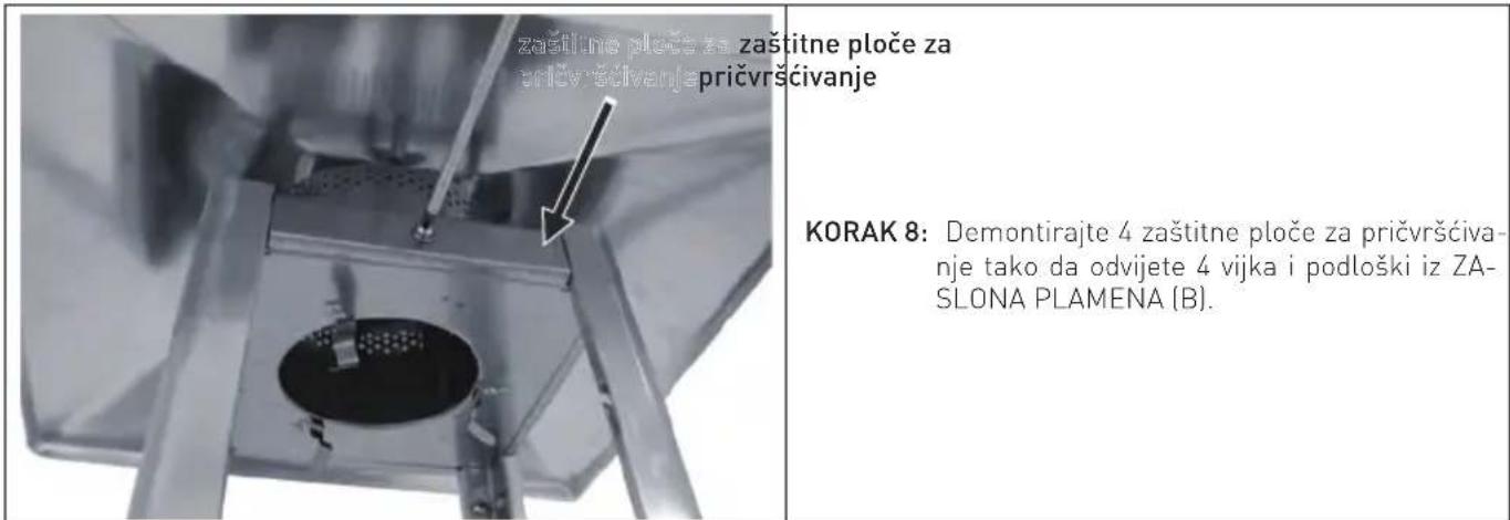
STEP 8: Unload 4PCS Guard Fastening Plates by un screwing 4PCS screws and washers from FLAME SCREEN (B).
natural_image
Close-up of a metal lattice structure with two white arrows pointing to the top edge (no text or symbols visible)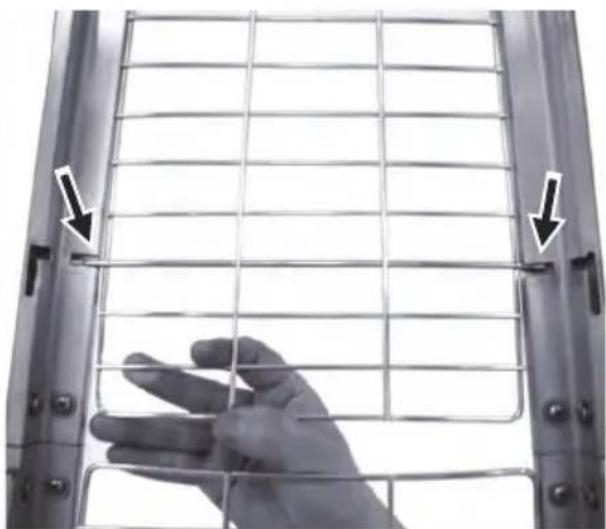
natural_image
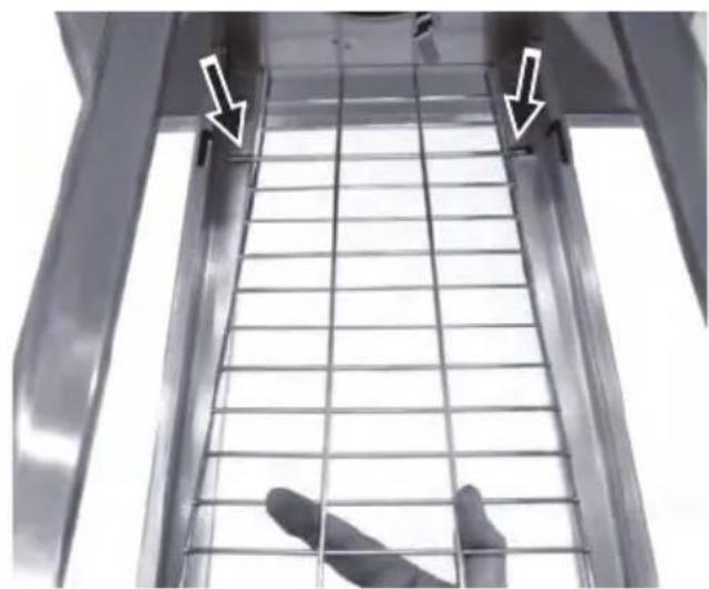
Close-up of a hand holding a metal grid fence, with arrows pointing to the lattice (no text or symbols visible)STEP 9: Same as Step 7 to align and Insert 3pcs Mesh Guard – Upper (C) into the inside slots of 3pcs Support Bar – Upper (E).
natural_image
Close-up of a transparent cylindrical scientific instrument with internal grid structure (no visible text or symbols)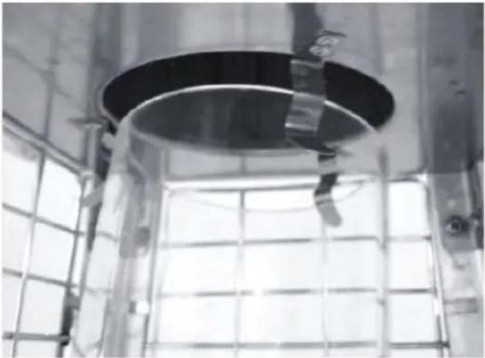
natural_image
Interior view of a large industrial facility with a circular metal tank and grid-patterned structure (no visible text or symbols)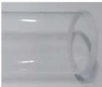
natural_image
Close-up of a transparent cylindrical object with a circular indentation on its side (no text or symbols visible)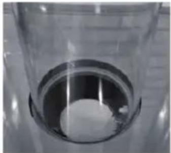
natural_image
Close-up of a transparent cylindrical container with a white circular object inside, no visible text or symbols.STEP 10: Hold Glass Tube (G) and insert one side of Glass Tube into Flame Screen (B) until touching the top of Flame Screen, then Insert another side of Glass Tube (G) into center of Tank Housing (top of Burner Assembly). NOTE: GLASS TUBE IS A FRAGILE PART, ASSEMBLE GLASS TUBE CAREFULLY AND SLOWLY!
natural_image
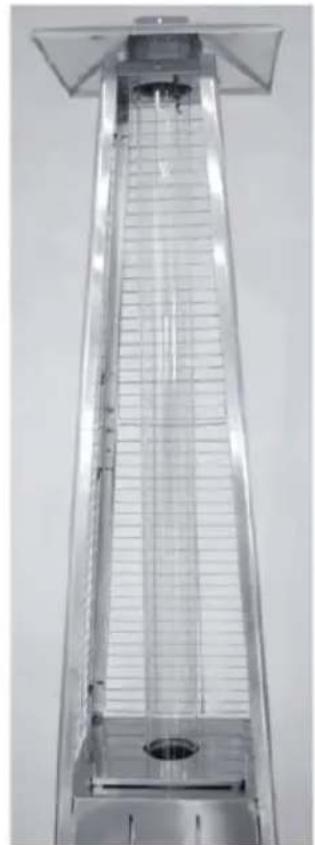
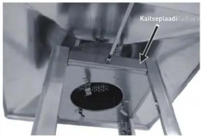
Exterior view of a tall industrial structure with internal grating and a circular opening (no visible text or symbols)STEP 11: Repeat Step 7 and step 9 to assemble the last Mesh Guard - Lower (D) and Mesh Guard - Upper (C). Replace 4pcs Guard Fastening Plates on the FLAME SCREEN (B) used 4pcs screws and washers.
natural_image
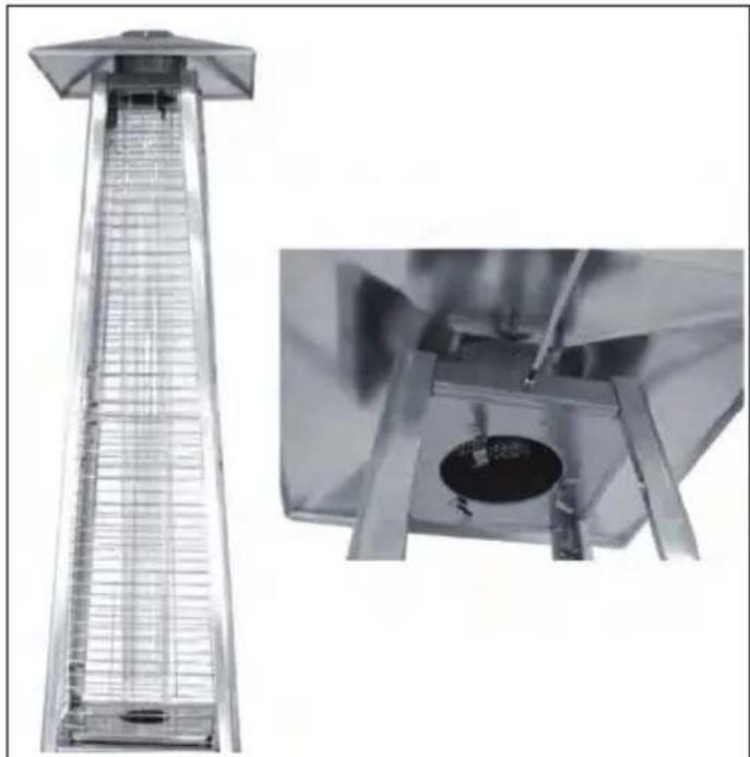
Interior view of a stainless steel appliance with a close-up inset showing internal components (no text or symbols visible)STEP 12: Insert & Fix the door to Tank Housing Assembly (K), then attach the Chain (L) to Burner Assembly (J).
WARNING: when Butune gas is used under the working pressure of 50mbar, the ring of flame screen (part B) must be removed.
Operating instructions
Before first use and after every gas cylinder change, gas delivery system must be purged of air before igniting! To do this, turn the control knob anti-clockwise to the pilot setting. Press knob in and hold for 3 minutes before attempting ignition.
Battery replacement
Remove impulse ignition cap from Burner Assembly (J) by turning cap counterclockwise. Install 1 AAA battery. Negative end of battery goes in first, then replace impulse ignition cap by turning cap clockwise.
To light the pilot
- Check all connections prior to each use.
- Turn on main gas supply at source.
- Press to turn control knob anti-clockwise to PILOT, see right photo.
- Hold knob depressed, press IGNITION button repeatedly until pilot flame is lit, then continue to hold the knob depressed for 10 seconds until the pilot remains it after releasing knob.
- If pilot fails to ignite or alight, press to turn knob clockwise to OFF and repeat.
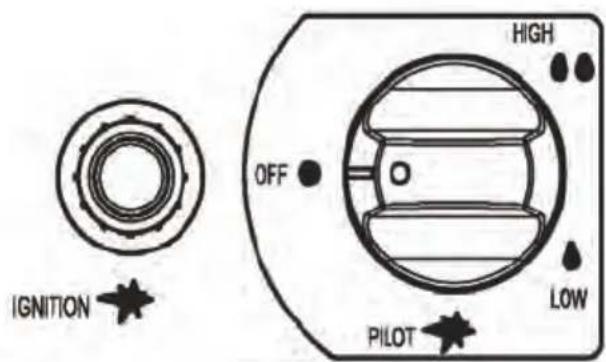
To light the patio heater
• The pilot should be lit and the knob set to PILOT.
- Hold knob depressed gently and turn anti-clockwise to LOW.
- When mesh glows lit, turn knob clockwise from Low to HIGH as needed.
Note: The burner may be noisy when initially turned on. To eliminate excessive noise from the burner, turn the control knob to the pilot position. Then turn the knob to the level of heat desired.
Re-lighting
- Turn Control Knob to OFF.
- Wait at least 5 minutes, to let gas dissipate, before attempting to re-light pilot.
- Repeat the "Lighting" steps.
To extinguish
- Hold knob depressed & turn the knob clockwise to 'OFF'
- Close the valve of the gas cylinder or the regulator after use.
- Close the gas bottle and allow this appliance to cool before moving the appliance.
Note: After use, some discoloration of the emitter screen is normal. Close regulator after use, allow the appliance to cool before moving.
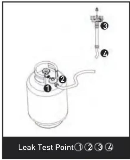
Leak testing
Never use a naked flame to check for leaks.
Never leak test while smoking.
The gas connections on this appliance are leak tested at the factory prior to shipment.
This appliance needs to be periodically checked for leaks and an immediate check is required if the smell of gas is detected.
- Make a soap solution using 1 part of liquid dish-washing soap to 3 parts water. The soap solution can be applied with a soap bottle, brush, or rag to the leak tested points shown in the figure above.
- The valve of the gas cylinder should be in the OFF position at this point of the leak test. Once the soapy solution is applied to the gas connections, the valve of the gas cylinder needs to be turned to the ON position.
- Soap bubbles will begin to form in the soapy solution if a leak is present.
- In case of a leak, turn off the gas supply. Tighten any leaking fittings, then turn the gas supply on and recheck.
Gas requirements
- Never use a gas cylinder with a damaged body, valve, collar, or foot ring. A dented or rusty gas tank may be hazardous and should be checked out by a gas supplier.
-
Never connect this appliance to an unregulated gas source.
-
When the appliance is not in use, turn the gas cylinder OFF.
- Always perform a leak test on gas connections whenever a cylinder is connected. If bubbles form in the leak test solution, do not use. Never use a flame to test for leaks.
Connecting to a gas cylinder
- Recommended to use 9 kg gas cylinder or refer to your gas supplier for suitable gas cylinder.
- Approved gas regulator is used according to appliances categories and countries listed in data plate. Approved flexible hose would be changed when the national conditions require it & consult the local regulations, these may differ.
- WARNING: assembly of the tubing must be conducted by some qualified tuber of destination countries.
-
Only change gas cylinders outdoors or in a well ventilated area away from naked flames and any other source of ignition (candle, cigarettes, other flame producing appliance....).
-
The gas cylinder must always be used in an upright position.
- Close the heater control knob by turning fully clockwise.
- Close the gas cylinder tap and then attach the regulator onto the gas cylinder.
- Tighten all connections firmly and with a spanner where appropriate. The cylinder should be located on the cylinder base.
- The gas cylinder must be fixed by cylinder belt, which is inside the housing, while installation.
- Check for leaks at all joints using soapy water. If a leak is found, tighten the joint and then re-test.
Securing the gas cylinder
natural_image
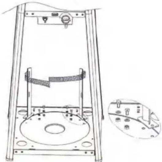
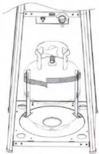
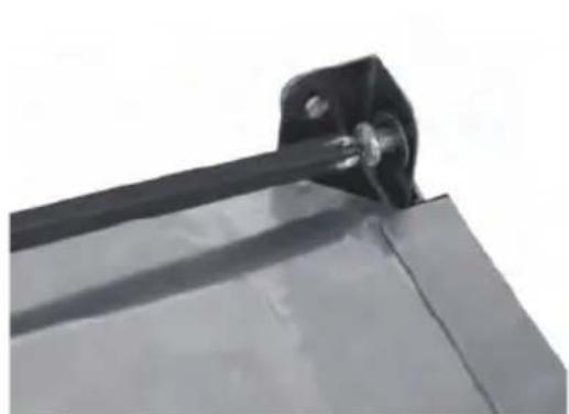
Technical line drawing of a mechanical testing apparatus with a circular base and side view showing internal components (no text or symbols)- Fix both brackets of Velcro tapes onto the base using 4pcs M6*12 bolts, M6 washer and M6 nuts.
- Position a gas cylinder inside the tank housing.
- Connect the gas cylinder with a regulator. Please refer to the instructions attached with the regulator on how to connect a regulator with the gas cylinder.
natural_image
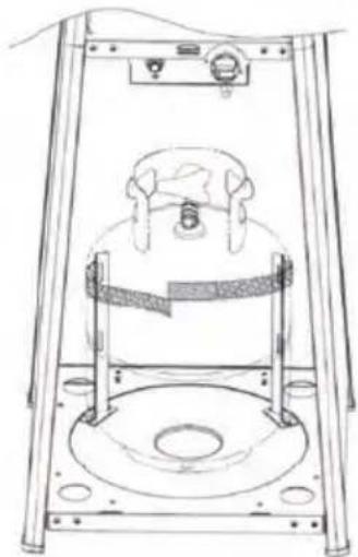
Technical line drawing of a mechanical testing apparatus with a central cylindrical component and mounting base (no text or symbols)- Stick Velcro tapes together as above photo illustrated. The tapes must be in a proper tightness for the gas cylinder.
CAUTION: Please take care that the Velcro tapes. DO NOT strain the regulator assembly.
Important safety rules
For use outdoors or in amply ventilated areas.
An amply ventilated area must have a minimum of 25% of the surface area open. The surface area is the sum of the walls surface.
The use of this appliance in enclosed areas can be dangerous and is PROHIBITED.
Children and adults should be aware of the high operating temperatures of areas above the post when operating this heater. Children should be carefully supervised when in the vicinity of the heater.
NEVER hang anything, including clothes or any other flammable items, on this heater.
DO NOT operate this heater unless it is fully assembled with its reflector in place. Respect the minimum clearances from combustible materials.
Maintenance
To enjoy years of outstanding performance from your heater, make sure you perform the following maintenance activities on a regular basis:
- Keep exterior surfaces clean.
- Use warm soapy water for cleaning. Never use flammable or corrosive cleaning agents.
- While washing your unit, be sure to keep the area around the burner and pilot assembly dry at all times. If the gas control is exposed to water in any way, DO NOT try to use it. It must be replaced.
- Airflow must be unobstructed. Keep controls, burner and circulation air passageways clean. Signs of possible blockage include:
• Gas odor with extreme yellow tipping of flame. - HeaterdoesNOT reach the desired temperature.
• Heater glow is excessively uneven.
• Heater makes popping noises.
- Spiders and insects can nest in burner or orifices. This dangerous condition can damage the heater and render it unsafe for use. Clean burner holes by using a heavy duty pipe cleaner. Compressed air may help clear away smaller particles.
- Carbon deposits may create a fire hazard. If any carbon deposits develop, clean dome and engine with warm soapy water.
Note: in a salt-air environment (such as near the sea), corrosion occurs more quickly than normal. Frequently check the corroded areas and repair them promptly.
Servicing
- Please consult your local dealer for servicing this appliance and replacement of its parts. The servicing of the appliance shall be carried out only by authorised personnel.
- CAUTION: do not use unauthorized parts or
components for this appliance, only use original equipment replacement parts and components. The use of unauthorized parts or components will void the warranty and can create an unsafe condition.
Storage
There is no limitation on the storage of the appliance indoors provided that the cylinder is removed from the appliance.
Between uses:
- Turn control knob OFF.
- Turn gas cylinder OFF.
Store heater upright in an area sheltered from direct contact with inclement weather (such as rain, sleet, hail, snow, dust and debris).
If desired, cover to protect exterior surfaces and to prevent build up in air passages.
Note: Wait until heater is cool before covering.
During periods of extended inactivity or when transporting:
- Turn control knob OFF.
- Disconnect gas cylinder and move to a secure, well ventilated location outdoors. DO NOT store in a location that will exceed 50°C.
Store heater upright in an area sheltered from direct contact with inclement weather (such as rain, sleet, hail, snow, dust and debris).
If desired, cover heater to protect exterior surfaces and to prevent build up in air passages.
Note: Wait until heater is cool before covering.
Troubleshooting
| IF THE PROBLEM IS AND THIS | CONDITION EXISTS THEN DO THIS | |
| Pilot won't light | Cylinder valve is closed Open valve | |
| Blockage in orifice or pilot tube Clean or replace orifice or pilot tube | ||
| Air in the gas line | Open gas line and bleed it (pressing control knob in) for not more than 1-2 minutes or until you smell gas | |
| Low gas pressure | Replace propane gas (disposable) cylinder with a new cylinder | |
| Igniter fails | Use match to light pilot (with match holder, see picture**); obtain new igniter and replace | |
| Pilot won't stay lit | Dirt build up around pilot Clean dirt from | around pilot |
| Connection between gas valve and pilot assembly is loose | Tighten connection and perform leak test | |
| Thermocouple is not operating correctly | Replace thermocouple | |
| Burner won't light | Gas pressure is low | Replace propane gas (disposable) cylinder with a new cylinder |
| Blockage in orifice Clear blockage | ||
| Control knob is not in "ON" position Turn control knob to "ON" position | ||
| Burner flame is lowNote: Do not operate heater below 5°C (40°F) | Gas pressure is low Replace gas cylinder | |
| Outdoor temperature is greater than 5°C (40°F) and tank is less than 25% full | Replace gas cylinder | |
| Supply hose is bent or kinked Straighten | hose and perform leak test on hose | |
| Control knob is fully "ON" | Turn control knob to "OFF", let it cool to room temperature and check burner and orifices for blockage | |
| Emitter glows unevenNote: Bottom 2.5cm of emitter normally does not normally glow | Gas pressure is low Replace gas cylinder | |
| Base is not on a level surface Place heater | on a level surface | |
| Heater not level Level heater | ||
| Carbon build-up Dirt or film | on reflector and emitter Clean reflector and emitter | |
| Thick black smoke Blockage | in burner | Turn control knob to "OFF", let it cool to room temperature and remove blockage and clean burner inside and outside. |
Warranty
Any defect affecting the functionality of the appliance which becomes apparent within one year after purchase will be repaired by free repair or replacement provided the appliance has been used and maintained in accordance with the instructions and has not been abused or misused in any way. Your statutory rights are not affected. If the appliance is claimed under warranty, state where and
when it was purchased and include proof of purchase (e.g. receipt).
In line with our policy of continuous product development we reserve the right to change the product, packaging and documentation specifications without notice.
Discarding & Environment
When decommissioning the appliance, the product must not be disposed of with other household waste. Instead, it is your responsibility to dispose to your waste equipment by handing it over to a designated collection point. Failure to follow this rule may be penalized in accordance with applicable regulations on waste disposal. The separate collection and recycling of your waste equipment at the time of disposal will help conserve natural re-
sources and ensure that it is recycled in a manner that protects human health and the environment.
For more information about where you can drop off your waste for recycling, please contact your local waste collection company. The manufacturers and importers do not take responsibility for recycling, treatment and ecological disposal, either directly or through a public system.
natural_image
Exterior view of a stainless steel filing cabinet with ventilation grilles and metal frame (no text or symbols visible)natural_image
Close-up of a mechanical assembly with visible components and a tool (no text or symbols)natural_image
Two views of a metal mechanical assembly with clamps and bolts (no text or symbols visible)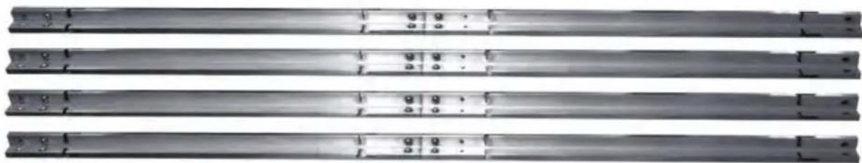
natural_image
Four identical metallic cylindrical rods arranged horizontally, each with a small circular mark on its side (no text or symbols visible)natural_image
Three views of a metallic mechanical device with structural components and mounting holes (no visible text or symbols)natural_image
Simple illustration of a metal table with a curved top and four legs, no text or symbols present.natural_image
Three-panel image showing a hand holding a metal rod, interacting with a metal bracket (no text or symbols visible)natural_image
Close-up of a metal grid fence structure with two vertical supports and directional arrows indicating measurement or alignment points (no text or symbols)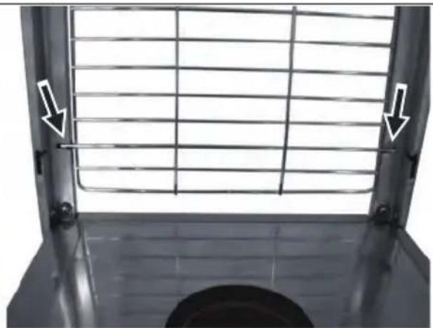
natural_image
Close-up of a metal grate with two white arrows pointing to the left side of the window (no text or symbols visible)natural_image
Close-up of a metal lattice structure with two white arrows pointing to the top edge (no text or symbols visible)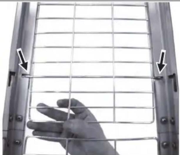
natural_image
Close-up of a hand holding a wire fence, with arrows pointing to the grid (no text or symbols visible)natural_image
Exterior view of a tall industrial vertical structure with internal grating and mounting base (no visible text or symbols)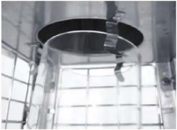
natural_image
Interior view of a large industrial facility with a circular metal structure and grid-patterned walls (no visible text or symbols)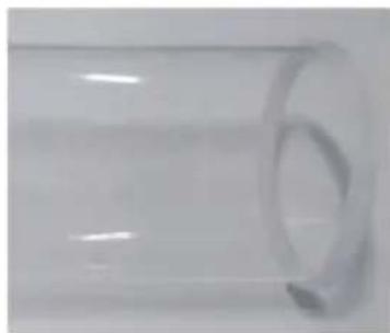
natural_image
Close-up of a transparent cylindrical object with a circular indentation on the side (no text or symbols visible)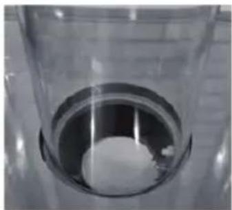
natural_image
Close-up of a transparent cylindrical container with a white spherical object inside, placed on a textured surface (no text or symbols visible)natural_image
Exterior view of a tall, wire-covered metal structure with a flat top (no text or symbols visible)
natural_image
Close-up of a mechanical component with a circular hole and metal supports (no visible text or symbols)natural_image
Interior view of a stainless steel appliance with a close-up inset showing internal components (no text or symbols visible)natural_image
Technical line drawing of a mechanical device with a circular base and mounting holes, shown with an inset detail (no text or symbols)natural_image
Technical line drawing of a mechanical testing apparatus with a central component and mounting base (no text or symbols)Montage terrasverwarming
Montage-instructies
natural_image
Exterior view of a stainless steel filing cabinet with ventilation grilles (no text or symbols visible)natural_image
Close-up of a mechanical assembly with a black component and a tool, no visible text or symbolsnatural_image
Technical illustrations of metal structural components including clamping, bracket assembly, and parallel plates (no text or symbols visible)natural_image
Three views of a metallic mechanical device with mounting brackets and a cylindrical opening (no text or symbols visible)natural_image
Close-up of a metallic table with a curved top and four legs, no visible text or symbolsnatural_image
Three-panel image showing a hand holding a tool over a metal bracket, with no visible text or symbols.natural_image
Metal fence structure with grid lines and mounting holes, no visible text or symbols
natural_image
Close-up of a metal grate structure with white arrows pointing to the side (no text or symbols visible)natural_image
Close-up of a metal lattice structure with two white arrows pointing to the top edge (no text or symbols visible)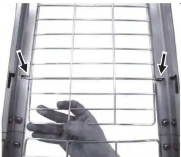
natural_image
Close-up of a hand holding a wire fence inside a metal frame, with arrows pointing to the grid (no text or symbols visible)natural_image
Close-up of a transparent cylindrical scientific instrument with measurement markings and a central hole (no visible text or symbols)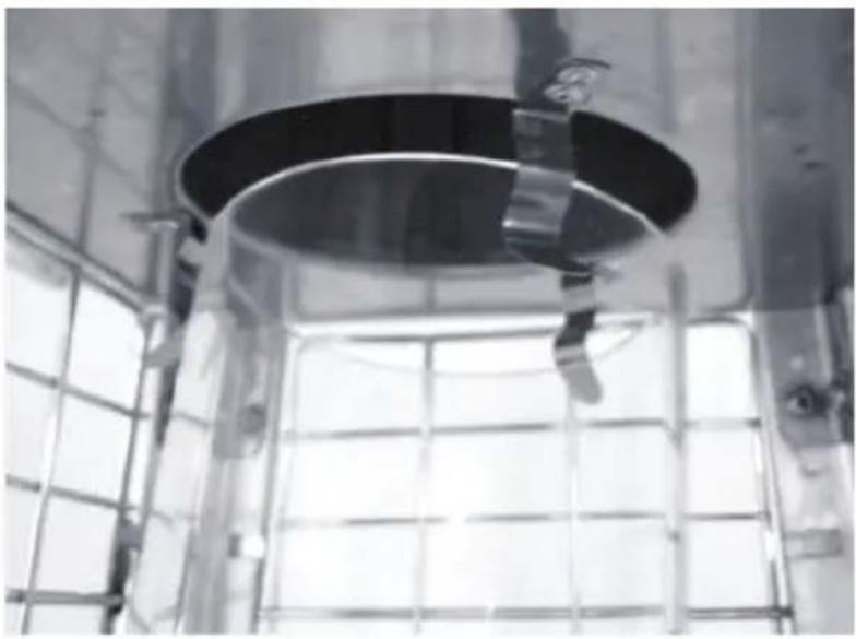
natural_image
Interior view of a stainless steel industrial tank with a circular metal lid and metal grating (no visible text or symbols)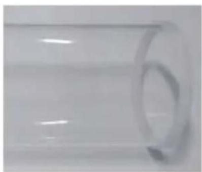
natural_image
Close-up of a transparent cylindrical object with a circular hole, no visible text or symbols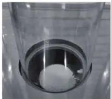
natural_image
Close-up of a transparent cylindrical container with a white spherical object inside, placed on a tiled surface (no text or symbols visible)natural_image
Exterior view of a tall industrial structure with internal grating and a circular opening (no visible text or symbols)natural_image
Interior view of a stainless steel appliance with a close-up inset showing a mechanical component (no text or symbols visible)natural_image
Technical line drawing of a mechanical testing frame with a circular base and internal components, shown alongside by an inset detail (no text or symbols)natural_image
Technical line drawing of a mechanical testing apparatus with a central circular component and mounting base (no text or symbols)natural_image
Exterior view of a stainless steel filing cabinet with ventilation grilles and doorways (no text or symbols visible)natural_image
Close-up of a mechanical assembly with tools and components, no visible text or symbolsnatural_image
Close-up of two metallic mechanical components with screws and fasteners, shown from different angles (no text or symbols visible)
natural_image
Pure electrical circuit lines without any symbols
natural_image
Pure electrical circuit lines without any symbols
natural_image
Pure electrical circuit lines without any symbols
natural_image
Pure electrical circuit lines without any symbolsnatural_image
Three views of a metallic mechanical device with mounting brackets and a cylindrical opening (no text or symbols visible)natural_image
Exterior view of a modern office building (no signage)natural_image
Close-up of a hand holding a test tube inserted into a metal frame, showing mechanical assembly (no text or symbols visible)natural_image
Metal cage structure with grid lines and mounting holes, no visible text or symbols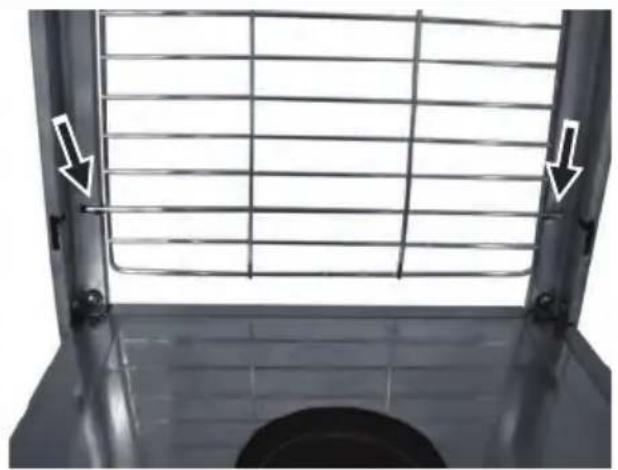
natural_image
Metal grate with grid pattern and two white arrows pointing to the side of the window (no text or symbols)natural_image
Close-up of a metal lattice structure with two white arrows pointing to the top edge (no text or symbols visible)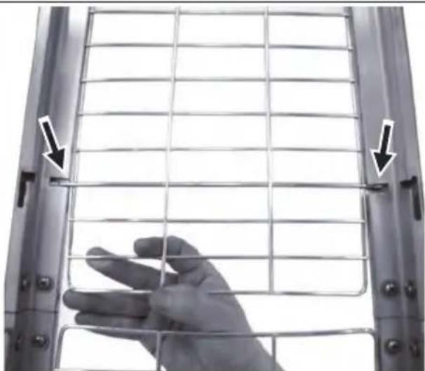
natural_image
Close-up of a hand holding a metal wire fence, with arrows pointing to the grid (no text or symbols visible)natural_image
Close-up of a transparent cylindrical scientific instrument with internal grid structure (no visible text or symbols)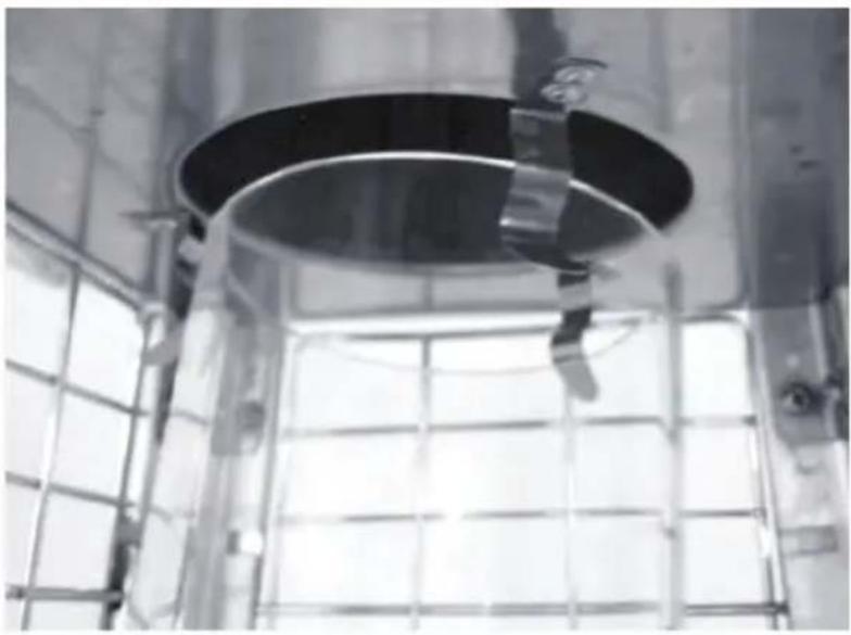
natural_image
Interior view of a large industrial facility with a circular metal ceiling and glass partition (no visible text or symbols)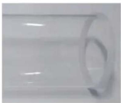
natural_image
Close-up of a transparent cylindrical object with a circular indentation on its side (no text or symbols visible)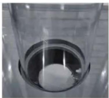
natural_image
Close-up of a transparent cylindrical container with a white circular object inside, placed on a surface (no text or symbols visible)natural_image
Technical line drawing of a mechanical testing apparatus with a circular base and mounting holes, shown alongside by an inset view (no text or symbols)natural_image
Technical line drawing of a mechanical testing apparatus with a central cylindrical component and mounting base (no text or symbols)Assemblage de parasol chauffant
natural_image
Exterior view of a stainless steel filing cabinet with ventilation grilles (no text or symbols visible)natural_image
Close-up of a mechanical assembly with a tool inserted, showing components like a black box and screws (no visible text or symbols)natural_image
Technical illustrations of metal structural components with fasteners and bolts, shown from multiple angles (no text or symbols visible)natural_image
Technical illustration of a metal mechanical device with three views: top view showing a pipe joint, side view showing a perforated base, and front view with a circular opening (no text or symbols visible)natural_image
Close-up of a metallic table with a curved top and four legs, no visible text or symbolsnatural_image
Three-panel image showing a hand holding a tool over a metal bracket, with no visible text or symbols.natural_image
Metal cage structure with grid lines and mounting feet, no visible text or symbols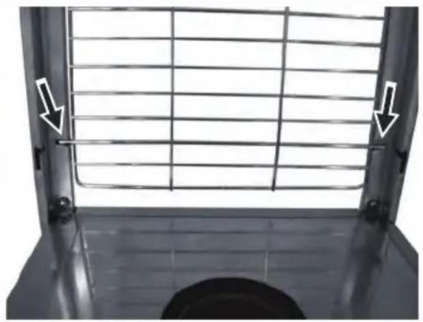
natural_image
Metal grate with grid pattern and two white arrows pointing to the side (no text or symbols)natural_image
Close-up of a metal lattice structure with two white arrows pointing to the top edge (no text or symbols visible)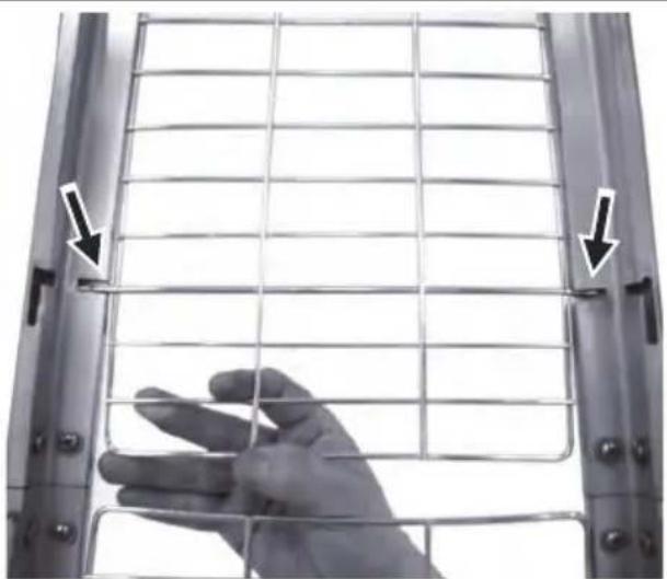
natural_image
Close-up of a hand holding a wire mesh fence, with arrows pointing to the grid (no text or symbols visible)natural_image
Close-up of a transparent cylindrical scientific instrument with internal grid structure and mounting bracket (no visible text or symbols)
natural_image
Interior view of a large industrial facility with a circular metallic ceiling and metal grid structure (no visible text or symbols)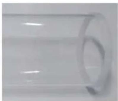
natural_image
Close-up of a transparent cylindrical object with a circular hole, no visible text or symbols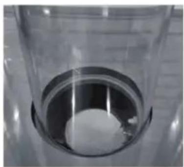
natural_image
Close-up of a transparent cylindrical container with a white spherical object inside, no visible text or symbols.natural_image
Exterior view of a tall industrial chimney with mesh insulation (no signage or text visible)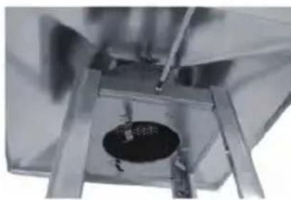
natural_image
Close-up of a metallic mechanical component with a circular hole and metal supports (no visible text or symbols)natural_image
Interior view of a stainless steel appliance with a circular inset showing a mechanical component (no visible text or symbols)natural_image
Technical line drawing of a mechanical testing frame with mounting holes and a close-up inset showing internal components (no text or symbols)natural_image
Technical line drawing of a mechanical testing apparatus with a central circular component and mounting base (no text or symbols)natural_image
Exterior view of a stainless steel industrial storage unit with ventilation slots and metal frame (no text or symbols visible)natural_image
Close-up of a mechanical assembly with tools and components, no visible text or symbolsnatural_image
Technical illustrations of metal structural components including clamping, bracket assembly, and parallel plates (no text or symbols visible)natural_image
Three views of a metallic mechanical device with mounting brackets and a cylindrical opening (no text or symbols visible)natural_image
Metal table with a curved top and four legs, no visible text or symbolsnatural_image
Three-panel image showing a hand holding a metal rod inserted into a metal frame, with no visible text or symbols.natural_image
Metal cage structure with grid lines and mounting feet, no visible text or symbols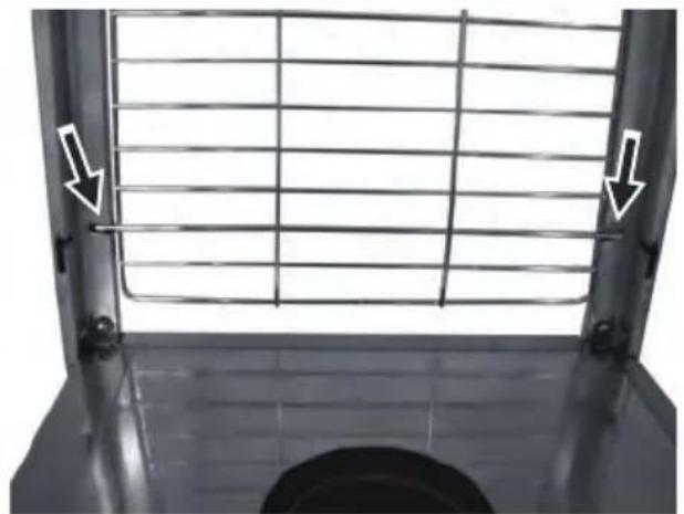
natural_image
Close-up of a metal grate with white arrows pointing to the side of the grate (no text or symbols visible)natural_image
Close-up of a metal lattice structure with two white arrows pointing to the top edge (no text or symbols visible)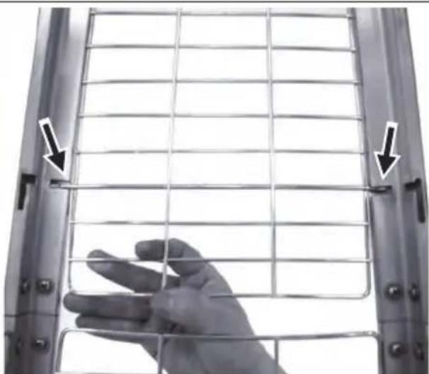
natural_image
Close-up of a hand holding a metal grid fence, with arrows pointing to the structure (no text or symbols visible)natural_image
Close-up of a transparent cylindrical scientific instrument with internal grid structure (no visible text or symbols)
natural_image
Interior view of a large industrial facility with a circular metallic structure and metal grid panel (no visible text or symbols)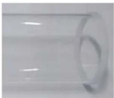
natural_image
Close-up of a transparent cylindrical object with a circular hole, no visible text or symbols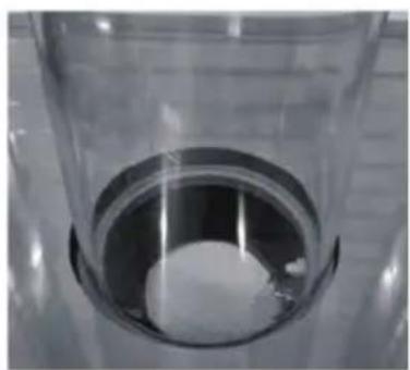
natural_image
Close-up of a transparent cylindrical container with a white spherical object inside, no visible text or symbols.natural_image
Exterior view of a tall industrial chimney with mesh insulation (no text or symbols visible)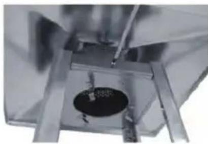
natural_image
Close-up of a metallic mechanical component with a circular hole and metal supports (no visible text or symbols)natural_image
Interior view of a stainless steel kitchen appliance with a close-up inset showing a metal bracket (no text or symbols visible)natural_image
Technical line drawing of a mechanical testing apparatus with a circular base and mounting holes, shown alongside by an inset detail (no text or symbols)natural_image
Technical line drawing of a mechanical testing apparatus with a central cylindrical component and mounting base (no text or symbols)natural_image
Exterior view of a stainless steel filing cabinet with ventilation grilles (no text or symbols visible)natural_image
Close-up of a mechanical assembly with tools and components, no visible text or symbolsnatural_image
Technical illustrations of metal structural components including clamps, brackets, and bolts (no text or symbols visible)natural_image
Three views of a metallic mechanical device with mounting brackets and a cylindrical opening (no text or symbols visible)natural_image
Simple illustration of a metallic table with a curved top and four legs, no text or symbols present.natural_image
Three-panel image showing a hand holding a test tube into a metal bracket, with no visible text or symbols.natural_image
Close-up of a metal grid fence structure with two vertical supports and directional arrows indicating measurement or alignment points (no text or symbols)
natural_image
Exterior view of a metal grate with white arrows pointing to the side panel (no text or symbols)natural_image
Close-up of a metal lattice structure with two white arrows pointing to the top edge and a finger pointing to the bottom (no text or symbols visible)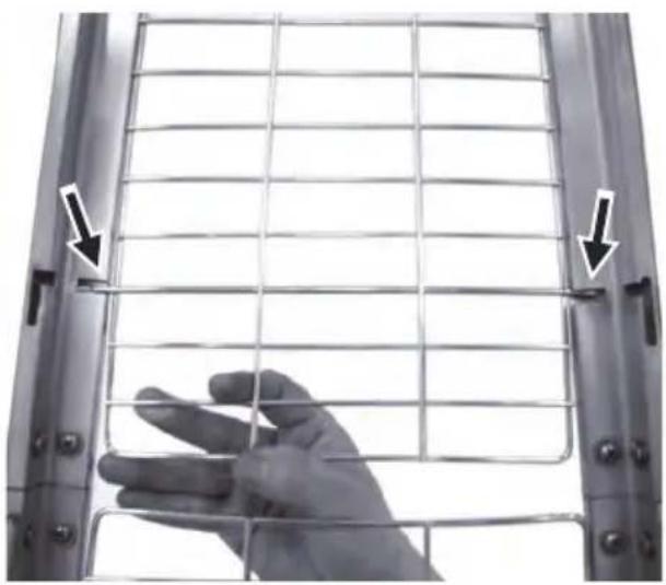
natural_image
Close-up of a hand holding a metal wire fence, with two arrows pointing to the grid (no text or symbols visible)natural_image
Close-up of a transparent cylindrical scientific instrument with internal grid structure (no visible text or symbols)
natural_image
Interior view of a stainless steel industrial facility with a circular tank and metal grating (no visible text or symbols)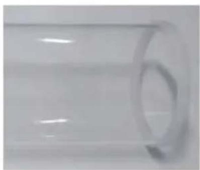
natural_image
Close-up of a transparent cylindrical object with a circular opening, no visible text or symbols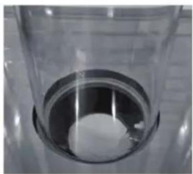
natural_image
Close-up of a transparent cylindrical container with a circular opening, containing a white substance (no text or symbols visible)natural_image
Exterior view of a tall industrial chimney with mesh insulation (no signage or text visible)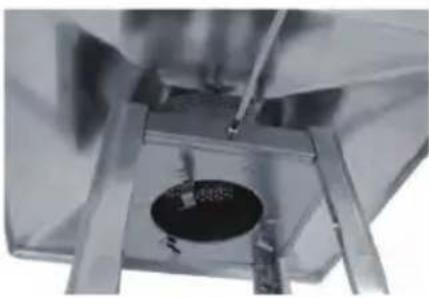
natural_image
Close-up of a mechanical or electronic component with a central circular component and metallic frame (no visible text or symbols)natural_image
Interior view of a stainless steel kitchen appliance with a close-up inset showing a metal bracket detail (no text or symbols visible)natural_image
Technical line drawing of a mechanical testing apparatus with a circular base and mounting holes, shown alongside by an inset detail (no text or symbols)natural_image
Technical line drawing of a mechanical testing apparatus with a central circular component and mounting base (no text or symbols)natural_image
Metallic stainless steel storage cabinet with ventilation slots and metal frame (no visible text or symbols)natural_image
Close-up of a mechanical assembly with metal components and a hand adjusting parts (no visible text or symbols)natural_image
Two views of a metal mechanical component with screws and fasteners (no text or symbols visible)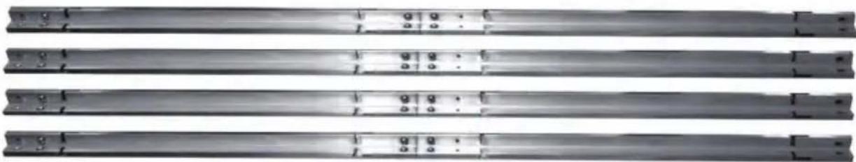
natural_image
Three identical metallic cylindrical rods arranged horizontally, each with a small circular mark and a small hole at the end (no text or symbols visible)natural_image
Three views of a metallic mechanical device with mounting brackets and a cylindrical component, showing structural details (no text or symbols visible)natural_image
Metal table with a curved top and four legs, no visible text or symbolsnatural_image
Three-panel image showing a hand holding a vertical tool, mounted on a metal frame with no visible text or symbols.natural_image
Metal grid fence structure with two vertical supports and directional arrows indicating force or movement (no text or symbols)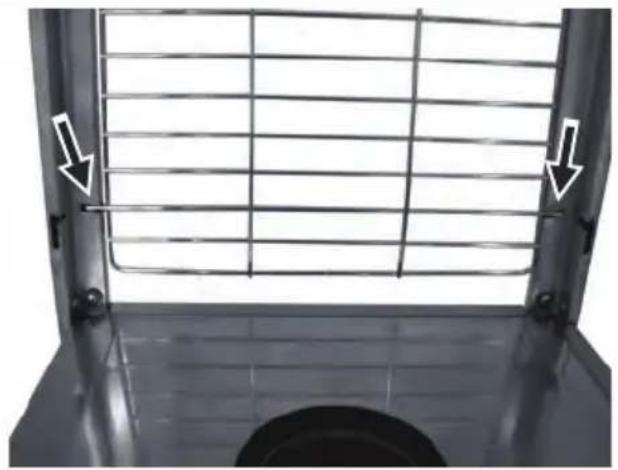
natural_image
Close-up of a metal grate with white arrows pointing to the side of the grille (no text or symbols visible)natural_image
Close-up of a metal lattice structure with two white arrows pointing to the top edge (no text or symbols visible)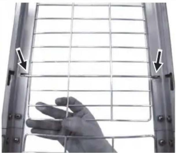
natural_image
Close-up of a hand holding a metal wire fence, with arrows pointing to the grid (no text or symbols visible)natural_image
Close-up of a transparent cylindrical scientific instrument with internal grid structure and mounting bracket (no visible text or symbols)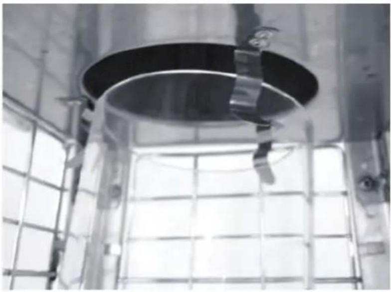
natural_image
Interior view of a large industrial facility with a circular metallic structure and metal grid panel (no visible text or symbols)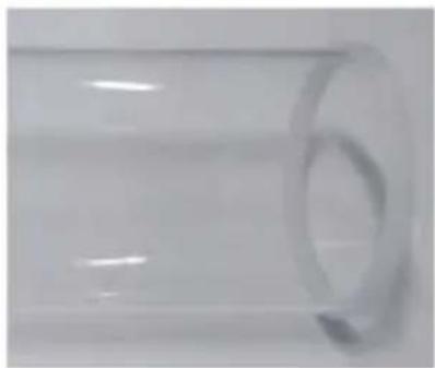
natural_image
Close-up of a transparent cylindrical object with a circular hole, no visible text or symbols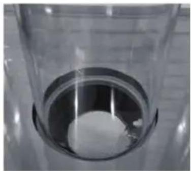
natural_image
Close-up of a metallic cylindrical container with a white spherical object inside, no visible text or symbols.natural_image
Exterior view of a tall, wire-covered metal structure with a flat top (no text or symbols visible)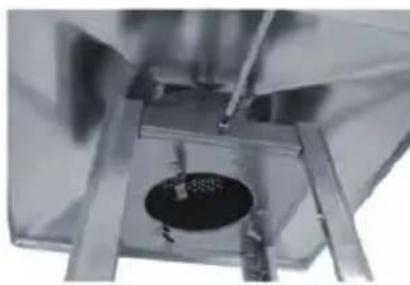
natural_image
Close-up of a metallic mechanical component with a circular hole and internal structure (no visible text or symbols)natural_image
Interior view of a stainless steel appliance with a close-up inset showing internal components (no visible text or symbols)natural_image
Technical line drawing of a mechanical testing frame with a circular base and attached clamping device (no text or symbols)natural_image
Technical line drawing of a mechanical testing apparatus with a central cylindrical component and mounting base (no text or symbols)natural_image
Exterior view of a stainless steel open storage cabinet with ventilation grilles (no text or symbols visible)natural_image
Close-up of a mechanical assembly with visible components and a hand holding a tool (no text or symbols)natural_image
Close-up of two metal mechanical components with bolts and fasteners, shown from different angles (no text or symbols visible)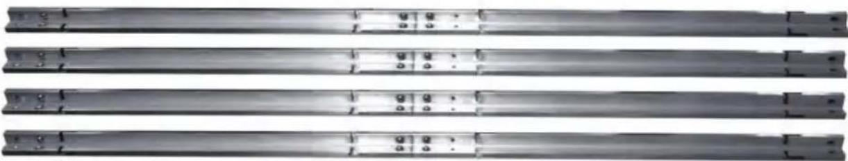
natural_image
Three identical metallic cylindrical rods arranged horizontally, each with a small inset showing internal features (no text or symbols visible)natural_image
Close-up of a metallic mechanical component with two black arrows pointing to features (no visible text or symbols)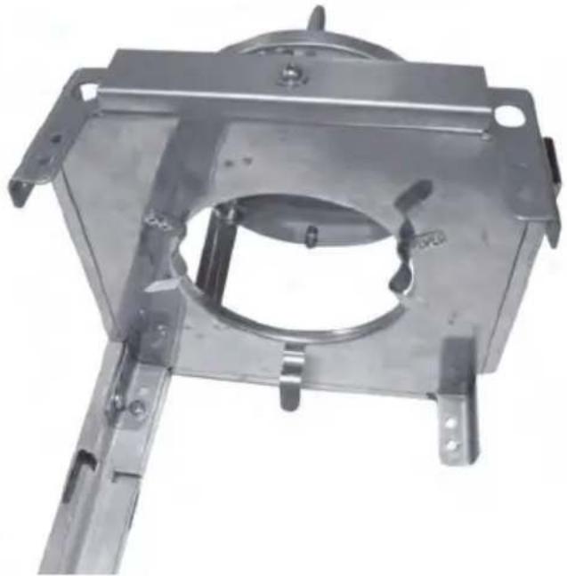
natural_image
Metal mechanical component with mounting flanges and central circular opening (no visible text or symbols)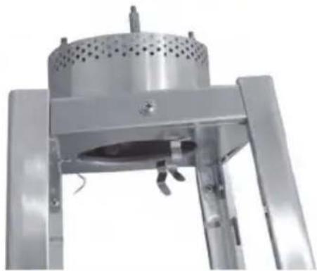
natural_image
Close-up of a metallic industrial device with perforated top and three legs (no visible text or symbols)natural_image
Metal table with a curved top and four legs, no visible text or symbolsnatural_image
Three-panel image showing a hand holding a metal rod, interacting with a metal bracket (no text or symbols visible)natural_image
Metal cage structure with grid lines and mounting holes, no visible text or symbols
natural_image
Metal grate with grid pattern and two white arrows pointing to the right side of a window (no text or symbols)BHMA 8: Unload 4PCS Guard Fastening Plates by unscrewing 4PCS screws and washers from FLAME SCREEN (B).
natural_image
Close-up of a metal lattice structure with two white arrows pointing to the top edge (no text or symbols visible)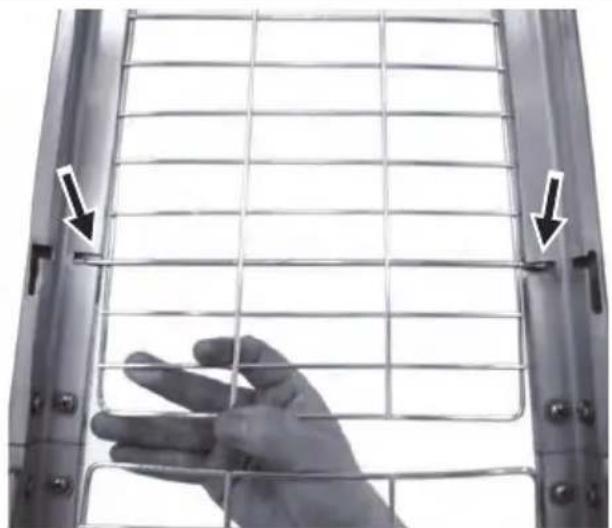
natural_image
Close-up of a hand holding a metal grid fence, with two arrows pointing to the edge (no text or symbols visible)natural_image
Close-up of a vertical metallic thermometer with mesh insulation and mounting bracket (no visible text or symbols)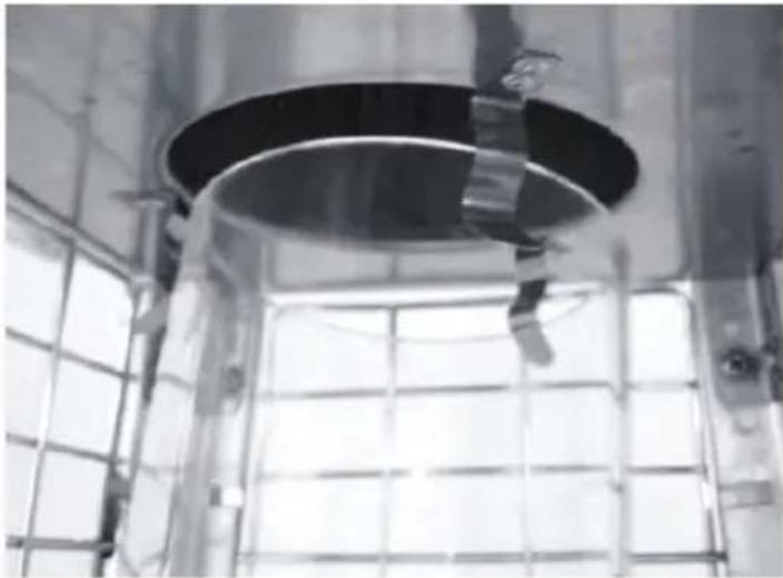
natural_image
Interior view of a large industrial facility with a circular metal structure and grid-patterned windows (no visible text or symbols)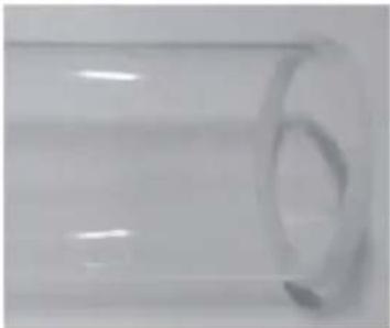
natural_image
Close-up of a transparent cylindrical object with a circular indentation on its side (no text or symbols visible)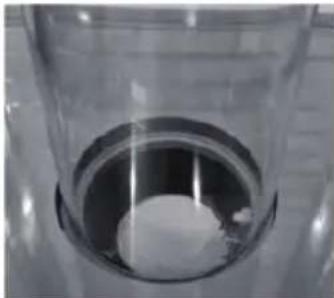
natural_image
Close-up of a glass container with a white substance inside, no visible text or symbolsnatural_image
Exterior view of a tall industrial chimney with metal grating (no signage or text visible)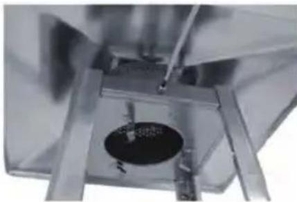
natural_image
Close-up of a metallic mechanical component with a central circular feature and metal plates (no visible text or symbols)natural_image
Interior view of a stainless steel appliance with open lid and internal compartments, showing a close-up inset of a mechanical component (no text or symbols visible)natural_image
Technical line drawing of a mechanical testing apparatus with a circular base and side plate, shown alongside by an inset detail (no text or symbols)natural_image
Technical line drawing of a mechanical testing apparatus with a central component and mounting base (no text or symbols)Montaža podne grijalice
Upute za montažu
- Popis potrebnog alata: Križni odvijač
- Otopina za detekciju curenja od jednog dijela deterdženta i tri dijela vode
- Prvo lagano zavijte sve matice i vijke. Pritegnite sve spojeve nakon završetka montaže. To vam olakšava rad i povećava stabilnost uređaja.
natural_image
Exterior view of a stainless steel filing cabinet with ventilation grilles (no text or symbols visible)KORAK 1: Položite sklop kućišta spremnika (K). Otvorite vrata i izvadite dijelove..
natural_image
Close-up of a mechanical assembly with tools and components, no visible text or symbolsKORAK 2: Držite kućište spremnika u donjem položaju Učvrstite sklop plamenika (J) u kućište spremnika pomoću 4 standardna vijka i podloški (BB).
natural_image
Technical illustrations of metal structural components with mounting holes and fasteners (no text or symbols visible)KORAK 3: Odvijte 2 standardna vijka i podloške (BB) s potporne šipke – donje (F). Umetnite potpornu šipku – gornju (E) na potpornu šipku – donju (F) i učvrstite pomoću 2 standardna vijka i podloške (BB). Ponovite ovaj korak da biste povezali preostala 3 kompleta potpornih šipki
natural_image
Three views of a metallic mechanical device with structural components, showing assembly and mounting details (no visible text or symbols)KORAK 4: Odvijte 2 standardna vijka i podloške (BB) kao što je prikazano strelicom na potpornoj šipki – GORNJOJ (E). Postavite zaslon plamena (B) na vrh cijele potporne šipke i pričvrstite pomoću 2 standardna vijka i podloške. Ponovite ovaj korak za spajanje zaslona s plamenom (B) s preostala 3 kompleta potpornih šipki.
natural_image
Close-up of a metallic table with a curved top and four legs, no visible text or symbolsKORAK 5: Postavite reflektor (A) na zaslon plamena (B) i učvrstite pomoću 4 MATICE S KAPICOM M6 (AA).
natural_image
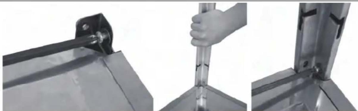
Three-panel image showing a hand holding a metal rod, interacting with a metal bracket (no text or symbols visible)natural_image
Two views of a metal grate structure with arrows pointing to structural details (no text or symbols present)KORAK 7: Poravnajte i umetnite zaštitnu mrežicu – donju (D) u unutrašnje utore potpore šipke – donje (F). Ponovite ovaj korak za umetanje 2 zaštitne mrežice – donje (D).
natural_image
Two-panel black-and-white photo showing hand positioning on a metal lattice panel, with arrows pointing to structural details (no text or symbols visible)natural_image
Exterior view of a vertical metallic structure with internal grid pattern (no text or symbols)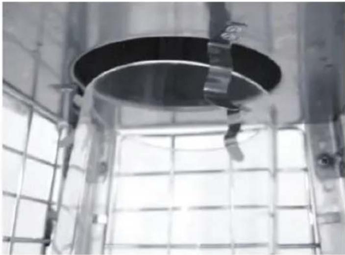
natural_image
Interior view of a large industrial facility with a circular metal ceiling and grid-patterned window (no visible text or symbols)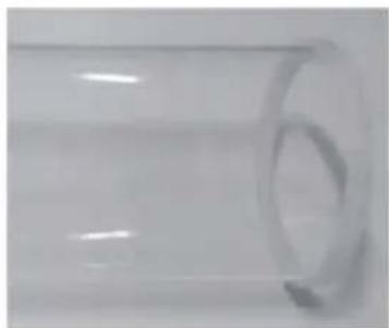
natural_image
Close-up of a transparent cylindrical object with a circular indentation on its side (no text or symbols visible)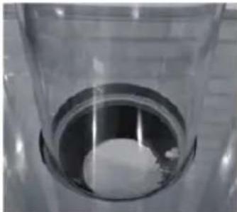
natural_image
Close-up of a glass container with a white substance inside, no visible text or symbolsKORAK 10: Držite staklenu cijev (G) i umetnite jednu stranu staklene cijevi na zaslon plamena (B) sve dok ne dodirnete vrh zaslona plamena, a zatim umetnite drugu stranu staklene cijevi (G) u središte spremnika (vrh sklopa plamenika).
NAPOMENA: STAKLENA CIJEV JE LOMLJIVI DIO, MONTIRAJTE STAKLENU CIJEV PAŽLJIVO I POLAKO!
natural_image
Exterior view of a tall industrial chimney with grid-patterned ventilation (no text or symbols visible)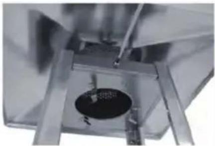
natural_image
Close-up of a metallic mechanical component with a central circular feature and surrounding metal plates (no visible text or symbols)natural_image
Interior view of a stainless steel appliance with a close-up inset showing internal components (no visible text or symbols)KORAK 12: Umetnite i učvrstite vrata na kućište spremnika (K), zatim spojite lanac (L) na sklop plamenika (J).
UPOZORENJE: kada se butan koristi pod radnim tlakom od 50 mbara, mora se ukloniti zaštita prstena za plamen (dio B).
Upute za rukovanje
natural_image
Technical line drawing of a mechanical testing frame with mounting holes and a close-up inset showing internal components (no text or symbols)- Oba držača čičak trake učvrstite na podlogu pomoću 4 vijka M6*12, podložaka M6 i matica M6.
- Postavite plinsku bocu unutar kućišta spremnika.
- Spojite plinsku bocu s regulatorom. Pogledajte upute priložene uz regulator o povezivanju regulatora s plinskom bocom.
natural_image
Technical line drawing of a mechanical testing apparatus with a central component and mounting base (no text or symbols)Sestava ohřívače
Montážní návod
natural_image
Metallic stainless steel storage cabinet with ventilation grilles and lid (no visible text or symbols)natural_image
Close-up of a mechanical assembly with tools and components, no visible text or symbolsnatural_image
Technical illustrations of metal mechanical components with fasteners and fasteners (no text or symbols visible)natural_image
Three views of a metallic mechanical device with mounting brackets and a cylindrical component, showing structural details (no text or symbols visible)natural_image
Close-up of a metallic table with a curved top and four legs, no visible text or symbolsnatural_image
Three-panel image showing a hand holding a metal rod, interacting with a metal bracket (no text or symbols visible)natural_image
Two-panel image showing metal grid structure with arrows pointing to structural elements (no text or symbols)natural_image
Two-panel black-and-white photo showing a hand interacting with a wire mesh fence, with arrows pointing to the components (no text or symbols visible)natural_image
Exterior view of a tall industrial vertical structure with internal grating and mounting base (no visible text or symbols)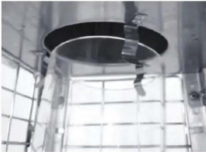
natural_image
Interior view of a large industrial facility with a circular duct and metal frame structure (no visible text or symbols)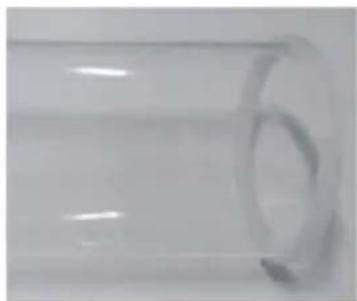
natural_image
Close-up of a transparent cylindrical object with a circular indentation on the side (no text or symbols visible)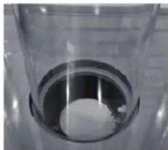
natural_image
Close-up of a glass container with a white cylindrical object inside, no visible text or symbolsnatural_image
Exterior view of a tall industrial chimney with mesh insulation (no signage or text visible)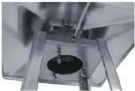
natural_image
Close-up of a metallic mechanical component with a circular dark object inserted into a square base (no visible text or symbols)natural_image
Interior view of a stainless steel kitchen appliance with open door and circular vent, showing internal components and a close-up inset (no text or symbols visible)natural_image
Technical line drawing of a mechanical testing apparatus with mounting holes and a close-up inset showing internal components (no text or symbols)natural_image
Technical line drawing of a mechanical testing apparatus with no visible text or symbolsTeraszfütő egység
natural_image
Metallic stainless steel storage cabinet with ventilation grilles and lid (no visible text or symbols)natural_image
Close-up of a mechanical assembly with tools and components, no visible text or symbolsnatural_image
Technical illustrations of metal frame components including clamps and parallel rods (no text or symbols visible)natural_image
Three views of a metallic mechanical device with mounting brackets and a cylindrical component, showing structural details (no text or symbols visible)natural_image
Close-up of a metallic table with a curved top and four legs, no visible text or symbolsnatural_image
Three-panel image showing a hand holding a metal rod, interacting with a metal bracket (no text or symbols visible)natural_image
Two-panel image showing a metal fence structure with arrows pointing to structural details (no text or symbols present)natural_image
Two-panel black-and-white photo showing hand positioning on a metal grid fence, with arrows pointing to structural details (no text or symbols)natural_image
Exterior view of a vertical metallic heating element with grid pattern and mounting bracket (no text or symbols)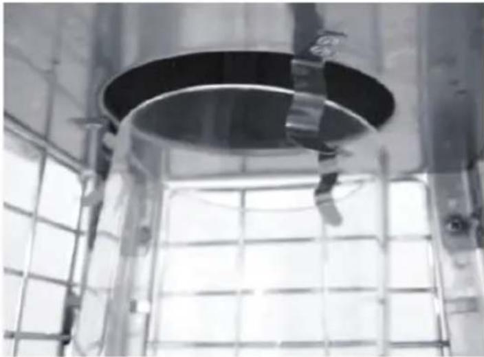
natural_image
Interior view of a large industrial facility with a circular metal structure and grid-patterned walls (no visible text or symbols)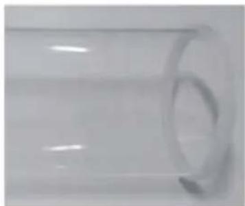
natural_image
Transparent cylindrical object with a circular indentation on its side (no text or symbols visible)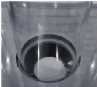
natural_image
Close-up of a transparent cylindrical container with a white substance inside, placed on a surface (no text or symbols visible)natural_image
Exterior view of a tall industrial chimney with mesh insulation (no signage or text visible)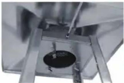
natural_image
Close-up of a mechanical component with a circular hole and metal frame (no visible text or symbols)natural_image
Interior view of a stainless steel appliance with internal compartments and a close-up inset showing a component detail (no text or symbols visible)natural_image
Technical line drawing of a mechanical testing frame with mounting holes and a close-up inset showing internal components (no text or symbols)natural_image
Technical line drawing of a mechanical testing apparatus with a central component and mounting base (no text or symbols)Satio küttesölm
Montaaži juhised
natural_image
Exterior view of a stainless steel industrial cabinet with ventilation grilles and door panel (no text or symbols visible)natural_image
Close-up of a mechanical assembly with visible components and a gloved hand (no text or symbols)natural_image
Technical illustrations of metal structural components including clamping, bracket assembly, and parallel plates (no text or symbols visible)natural_image
Close-up of a metallic mechanical component with two black arrows pointing to features (no visible text or symbols)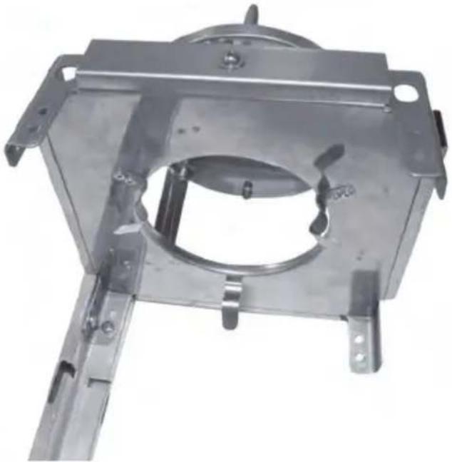
natural_image
Metal mechanical bracket component with mounting flanges and central circular opening (no text or symbols visible)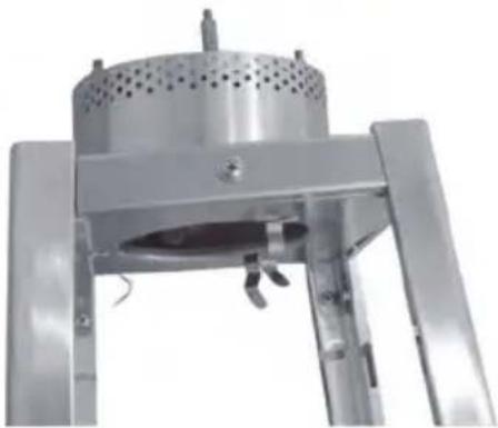
natural_image
Mechanical device with perforated top and metal frame (no visible text or symbols)natural_image
Exterior view of a modern office building (no signage)natural_image
Close-up of a metal bracket with a cylindrical rod inserted, mounted on a flat surface (no text or symbols visible)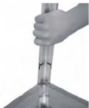
natural_image
Close-up of a hand holding a cylindrical object with a transparent tube inserted, against a plain background (no text or symbols visible)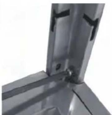
natural_image
Close-up of a metallic mechanical bracket with mounting holes and a central bolt (no text or symbols visible)natural_image
Close-up of a metal grid fence with two vertical supports and directional arrows indicating measurement or force points (no text or symbols)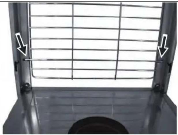
natural_image
Metal grate with grid pattern and two white arrows pointing to the side of the window (no text or symbols)- SAMM: Joondage ja sisestage vörkkaitse – alumine (D) tugilati – alumine (F) sisepiludesse. Korrake seda sammu, et sisestada 2 tk vörkkaitse – alumine (D).
natural_image
Close-up of a metal lattice structure with two arrows pointing to the top edge (no text or symbols visible)
natural_image
Close-up of a hand holding a wire mesh fence, with arrows pointing to the grid (no text or symbols visible)natural_image
Exterior view of a tall, transparent cylindrical structure with internal grid pattern (no text or symbols)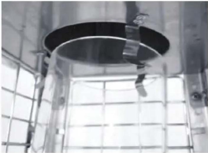
natural_image
Interior view of a large industrial facility with a circular metal ceiling and grid-patterned window (no visible text or symbols)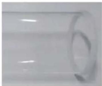
natural_image
Close-up of a transparent cylindrical object with a circular hole, no visible text or symbols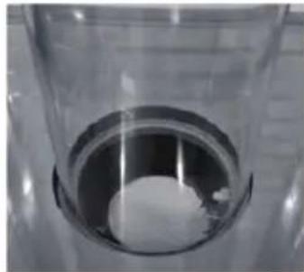
natural_image
Close-up of a transparent cylindrical container with a white spherical object inside, no visible text or symbols.natural_image
Exterior view of a tall industrial chimney with grid-patterned insulation (no text or symbols visible)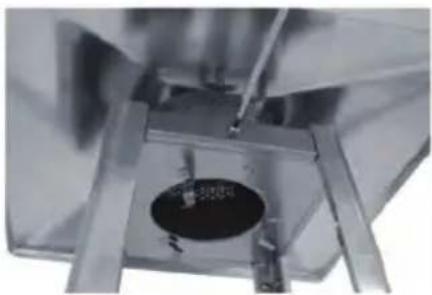
natural_image
Close-up of a mechanical component with a central circular feature and surrounding metal supports (no visible text or symbols)natural_image
Interior view of a stainless steel appliance with internal compartments and a close-up inset showing a component detail (no text or symbols visible)natural_image
Technical line drawing of a mechanical testing frame with mounting holes and a close-up inset showing internal components (no text or symbols)natural_image
Technical line drawing of a mechanical testing apparatus with a central circular component and mounting base (no text or symbols)Olulised ohutusreeglid
natural_image
Metallic stainless steel drawer with ventilation slots and metal frame (no text or symbols visible)- SOLIS: Nolaist tvertnes korpusa mezglu (K). Atveriet durvis un iznemiet visas detalas.
natural_image
Close-up of a mechanical assembly with a tool and component, no visible text or symbols- DARBIBA: Turiet tvertnes korpusu atgulšanas pozicijā. Piestipriniet degla mezglu (J) pie tvertnes korpusa, izmantojot 4 gab. standarta skrūves un paplāksnes (BB).
natural_image
Technical illustrations of metal structural components including clamps, beams, and rods (no text or symbols visible)natural_image
Close-up of a metallic mechanical component with two black arrows pointing to features (no visible text or symbols)
natural_image
Metal mechanical component with mounting flanges and central circular opening (no visible text or symbols)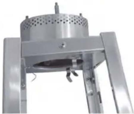
natural_image
Close-up of a metallic industrial device with perforated top and three legs (no visible text or symbols)natural_image
Metal table with a curved top and two legs, no visible text or symbols- SOLIS: Novietojiet reflektoru (A) uz liesmas ekrāna (B) un nostipriniet, izmantojot 4 gab. M6 CAP NUT (AA).

natural_image
Close-up of a metal bracket with a black rod inserted, mounted on a flat surface (no text or symbols visible)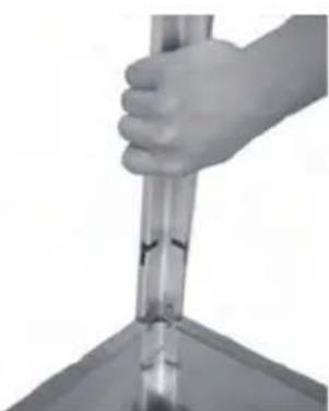
natural_image
Close-up of a hand holding a transparent cylindrical object over a surface (no text or symbols visible)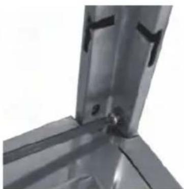
natural_image
Close-up of a metallic structural joint or bracket component (no visible text or symbols)natural_image
Exterior view of a vertical metallic structure with internal grid pattern (no text or symbols)
natural_image
Interior view of a large industrial facility with a circular metal ceiling and grid-patterned window (no visible text or symbols)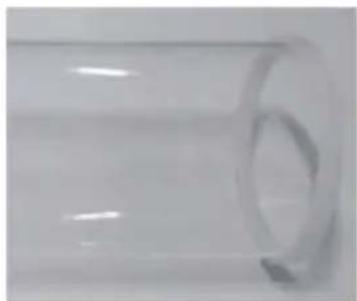
natural_image
Close-up of a transparent cylindrical object with a circular indentation on the side (no text or symbols visible)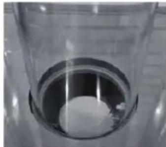
natural_image
Close-up of a transparent cylindrical container with a white spherical object inside, no visible text or symbols.natural_image
Exterior view of a tall industrial chimney with mesh insulation (no signage or text visible)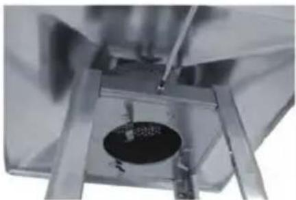
natural_image
Close-up of a metallic mechanical component with a central circular feature and a tool inserted (no visible text or symbols)natural_image
Interior view of a stainless steel appliance with internal compartments and a close-up inset showing a mechanical component (no text or symbols visible)- DARBIBA: levietojiet un nostipriniet durvis pie tvertnes korpusa mezgla (K), tad pievienojiet kēdi (L) pie degla mezgla (J).
natural_image
Technical line drawing of a mechanical testing frame with mounting holes and a close-up inset showing internal components (no text or symbols)natural_image
Technical line drawing of a mechanical testing apparatus with a central component and mounting base (no text or symbols)natural_image
Exterior view of a stainless steel filing cabinet with ventilation grilles (no text or symbols visible)natural_image
Close-up of a mechanical assembly with tools and components, no visible text or symbolsnatural_image
Technical illustrations of metal structural components including clamps, brackets, and bolts (no text or symbols visible)natural_image
Close-up of a metallic mechanical component with two black arrows pointing to features (no visible text or symbols)
natural_image
Metal mechanical component with mounting flanges and central circular opening (no visible text or symbols)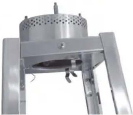
natural_image
Metallic industrial device with perforated top and side legs, no visible text or symbolsnatural_image
Metal table with a curved top and four legs, no visible text or symbols5 ETAPAS: Istatykite reflektoriy (A) j liepsnos tinklelj (B) ir pritvirtinkite naudodami 4 vnt. M6 CAP NUT (AA).
natural_image
Close-up of a metal bracket with a black cable inserted, mounted on a flat surface (no text or symbols visible)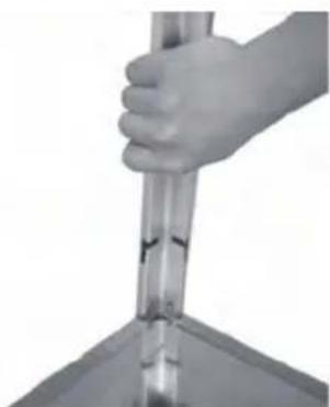
natural_image
Close-up of a hand holding a transparent cylindrical object over a surface (no text or symbols visible)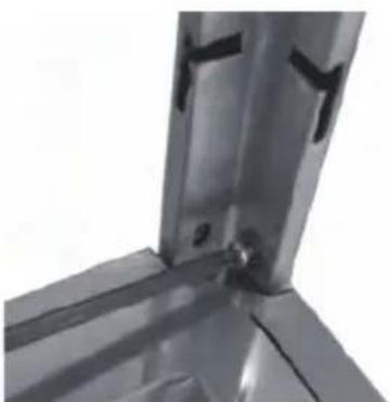
natural_image
Close-up of a metallic structural joint or bracket component (no visible text or symbols)natural_image
Exterior view of a tall, transparent cylindrical structure with internal grid pattern (no text or symbols)
natural_image
Interior view of a large industrial facility with a circular metal ceiling and grid-patterned window (no visible text or symbols)
natural_image
Close-up of a transparent cylindrical object with a circular hole, no visible text or symbols
natural_image
Close-up of a transparent cylindrical container with a white circular opening, containing a small white object inside (no text or symbols visible)natural_image
Exterior view of a tall industrial chimney with grid-patterned insulation (no text or symbols visible)
natural_image
Close-up of a mechanical component with a central circular feature and surrounding metal supports (no visible text or symbols)natural_image
Interior view of a stainless steel appliance with internal compartments and a close-up inset showing a component detail (no text or symbols visible)Operating instructions
natural_image
Technical line drawing of a mechanical testing frame with mounting holes and a close-up inset showing internal components (no text or symbols)natural_image
Technical line drawing of a mechanical testing apparatus with a central circular component and mounting base (no text or symbols)Zostava horáka Patio
Návod na montáž
natural_image
Exterior view of a stainless steel filing cabinet with ventilation grilles and doorways (no text or symbols visible)natural_image
Close-up of a mechanical assembly with a tool inserted, showing components like bolts and a black component (no visible text or symbols)natural_image
Technical illustrations of metal structural components including clamps, brackets, and bolts (no text or symbols visible)natural_image
Three views of a metallic mechanical device with structural components and mounting holes (no visible text or symbols)natural_image
Close-up of a metallic table with a curved top and four legs, no visible text or symbolsKROK 5: Reflektor (A) umiestnite na rozptylovaciu mriežku plameňa a upevnite ho pomocou 4 UZAVRETÝCH MATÍC M6 (AA).
natural_image
Three-panel image showing a hand holding a metal rod, interacting with a metal bracket (no text or symbols visible)KROK 6: Z hornej časti zostavy plášta zásobníka (K) vyskrutkujte 8 štandardných skrutiek s podložkami (BB). Zmontované horné diely ohrievača zdvihnite a umiestnite ich na plášť zásobníka. Nosnú lištu zatlačte, ako je to znázornené na obrázku, a uistite sa, že každá nosná lišta je zasunutá do otvoru. Na spodku ich upevnite pomocou 8 štandardných skrutiek s podložkami (BB).
natural_image
Close-up of a metal grid fence with two vertical supports and directional arrows indicating measurement or force (no text or symbols)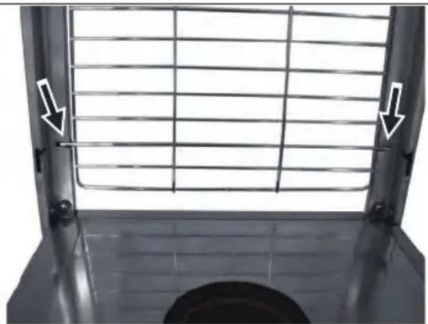
natural_image
Close-up of a metal grate with white arrows pointing to the side of the window (no text or symbols visible)natural_image
Close-up of a metal lattice structure with two white arrows pointing to the top edge, and a finger partially visible below (no text or symbols)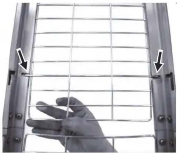
natural_image
Close-up of a hand holding a wire mesh fence, with arrows pointing to the grid (no text or symbols visible)natural_image
Close-up of a transparent cylindrical device with internal grid structure and mounting bracket (no visible text or symbols)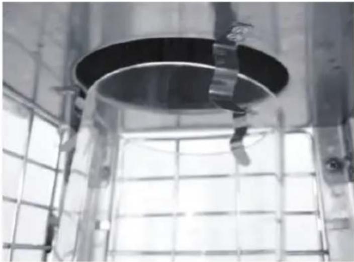
natural_image
Interior view of a large industrial facility with a circular metal structure and grid-patterned walls (no visible text or symbols)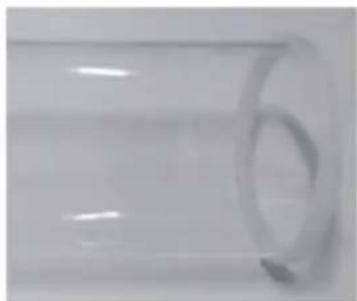
natural_image
Close-up of a transparent cylindrical object with a circular indentation on the side (no text or symbols visible)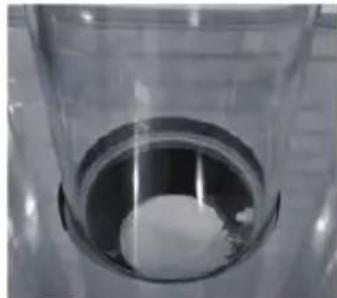
natural_image
Close-up of a transparent cylindrical container with a white spherical object inside, placed on a tiled surface (no text or symbols visible)natural_image
Exterior view of a tall industrial chimney with grid-patterned ventilation (no text or symbols visible)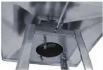
natural_image
Close-up of a metallic mechanical component with a circular hole and internal structure (no visible text or symbols)natural_image
Interior view of a stainless steel kitchen appliance with a close-up inset showing a component detail (no text or symbols visible)natural_image
Technical line drawing of a mechanical testing apparatus with mounting holes and a close-up inset showing internal components (no text or symbols)natural_image
Technical line drawing of a mechanical testing apparatus with no visible text or symbolsHendi Food Service Equipment GmbH
Ehring 15
Hendi Food Service Equipment Romania S.R.L.
PKS Hendi South East Europe SA
5 Metsovou Str.
18346 Moschato, Athens, Greece
Tel: +30 210 4839700
Email: info@pks-hendi.com
Hendi Italia S.R.L.
Via Leonardo da Vinci 4
39100 Bolzano (BZ), Italy
Tel: +39 800 727 438
Email: office.italy@hendi.eu
Hendi HK Ltd.
1208, 12/F Exchange Tower
33 Wang Chiu Road, Kowloon Bay, Hong Kong
Tel: +852 2154 2618
Email: info-hk@hendi.eu
Find Hendi on internet:
www.hendi.eu
www.facebook.com/HendiToolsforChefs
www.linkedin.com/company/hendi-food-service-equipment-b.v.
www.youtube.com/HendiEquipment
- EN: Changes, printing and typesetting errors reserved.

- Safety regulations
- Intended use
- Exploded view
- Patio heater assembly
- Assembly instructions
- Operating instructions
- Battery replacement
- To light the pilot
- To light the patio heater
- Re-lighting
- To extinguish
- Leak testing
- Never leak test while smoking.
- Gas requirements
- Connecting to a gas cylinder
- Securing the gas cylinder
- Important safety rules
- Maintenance
- Servicing
- Storage
- Warranty
- Discarding & Environment
- Montage terrasverwarming
- Montage-instructies
- Assemblage de parasol chauffant
- Montaža podne grijalice
- Upute za montažu
- Upute za rukovanje
- Sestava ohřívače
- Montážní návod
- Teraszfütő egység
- Satio küttesölm
- Montaaži juhised
- Olulised ohutusreeglid
- Zostava horáka Patio
- Návod na montáž
- Hendi Food Service Equipment GmbH
- Hendi Food Service Equipment Romania S.R.L.
- PKS Hendi South East Europe SA
- Hendi Italia S.R.L.
- Hendi HK Ltd.
- Find Hendi on internet:
Brand : Hendi
Model : 272404
Category : Heating