
272602 - Heating Hendi - Free user manual and instructions
Find the device manual for free 272602 Hendi in PDF.
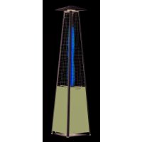
| Product type | Outdoor heater (patio heater) |
| Brand | Hendi |
| Model | 272602 |
| Usage | Outdoors or very well-ventilated spaces (at least 25% open surface) |
| Energy source | Gas (propane/butane) |
| Recommended gas bottle | 9 kg, must be secured with strap |
| Max flexible hose length | 1.5 m (compliant with EN16436:2014) |
| Ignition | Piezo (ignition button) or match via match holder |
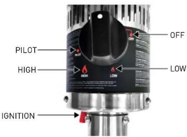
| Heat regulation | Positions OFF, PILOT, HIGH, LOW |
| Safety | Thermocouple, safety shut-off, leak protection, safety distance 0.9 m |
| Minimum operating temperature | 5°C |
| Main material | Steel, aluminum reflector |
| Deployed height (approx.) | Approximately 220 cm (retractable) |
| Weight (approx.) | Approximately 15 kg |
| Maintenance | Clean with soapy water, check leaks regularly, clean burner and orifices |
| Repairability | Original parts only, intervention by qualified technician |
| Warranty | 12 months from date of purchase |
Frequently Asked Questions - 272602 Hendi
User questions about 272602 Hendi
0 question about this device. Answer the ones you know or ask your own.
Ask a new question about this device
Download the instructions for your Heating in PDF format for free! Find your manual 272602 - Hendi and take your electronic device back in hand. On this page are published all the documents necessary for the use of your device. 272602 by Hendi.
USER MANUAL 272602 Hendi
You should read this user manual carefully before using the appliance.
Keep these instructions with the appliance.
XpaHntb pyKOBOCTBO BmecTe C yCtpoCTBOM.
ΦaAεTe aute cti odyiec μaiz e tm ouakeun.
Thank you for purchasing this Hendi appliance. Please read this manual carefully before connecting the appliance in order to prevent damage due to incorrect use. Read the safety regulations in particular very carefully.
Safety regulations
- This appliance must be used outdoors or in a well ventilated area, and should not be installed or used indoors.
- Change the gas cylinder in a well ventilated area, away from any inflammation sources.
- The cylinder must be stored outdoors or in a well ventilated area.
- Storage this appliance indoors is permissible only if gas cylinder is disconnected and removed from the appliance.
- Do not move this appliance when in operation, or after it has been turned off before the temperature has cooled down.
- Do not attempt to alter the appliance in any manner. Do not paint the radiant screen, control panel or reflector.
- Do not obstruct the ventilation holes of the cylinder housing.
- The appliance must be installed and gas cylinder stored in accordance with local gas fitting regulations.
- Shut off the valve at the gas cylinder or the regulator before moving the appliance.
- Use only the type of gas specified by the manufacturer.
- Repairs should be done by a qualified person.
- In case of violent wind, particular attention must be taken against tilting of the appliance.
- Check that the regulator seal is correctly fitted and able to fulfil its function.
- Close the gas supply at the valve of the gas cylinder or the regulator after use.
- Do not use this appliance until all connections have been leak tested.
- In the event of gas leakage, the appliance shall not be used or if alight, the gas supply shall be shut off and the appliance shall be investigated and rectified before it is used again.
- Checking the tubing or the flexible hose per month and each time the cylinder is changed.
- The tubing or the flexible hose must be changed within the prescribed intervals or with in one year. The flexible hose should not extended than 1.5m according to standard EN16436:2014.
- The hose assembly must be replaced prior to the appliance being put into operation if there is evidence of excessive abrasion or wear, or if the hose is damaged, and that the replacement hose assembly shall be that specified by the manufacturer.
- The heater should be inspected before use and at least annually by a qualified service person. More frequent cleaning may be required as necessary. It is imperative that control compartment, burners and circulating air passageways of the appliance be kept clean.
- Shut off and check heater immediately if any of the following conditions exist:
- The smell of gas in conjunction with extreme yellow tipping of the burner flames.
□ Heater does not reach a proper temperature. A temperature less than 5^ will cause restricted heat flow and the appliance will not work properly.
The appliance starts making popping noises during use (a slight popping noise is normal when the appliance is extinguished).
- The regulator & hose assembly must be located out of pathways where people may trip over it or in area where the hose will not be subject to accidental damage.
- Any guard or other protective device removed for servicing the heater must be replaced before operating the heater.
- Children and adults should be warned of the hazards of high surface temperatures and should stay away to avoid burns or clothing ignition.
- Young children and pets should be carefully supervised when they are in the area of the heater.
- Clothing or other flammable materials should not be hung from the appliance, or placed on or near the appliance.
- Do not place articles on or against this appliance. Certain material or items when stored under or near this appliance will be subjected to radiant heat and could be seriously damaged.
- Do not use or store flammable materials near this appliance.
- Do not spray aerosols in the vicinity of this appliance while it is in operation.
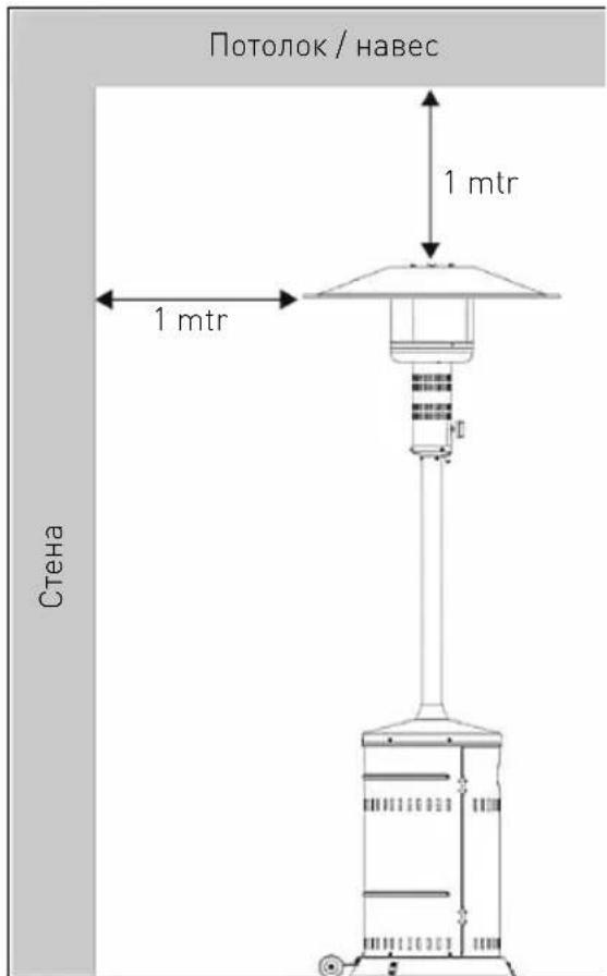
- Always maintain at least 0.9m clearance from combustible materials.
- Always position the appliance on a firm level surface. An amply ventilated area must have a minimum of 25% of the surface area open. The surface area is the sum of the walls surface.
- The injector in this appliance is not removable and the injector is only assembled by manufacture. This appliance is forbidden to convert from one gas pressure to another pressure.
- Do not connect the gas cylinder directly to the appliance without regulator.
- The gas cylinder must be fixed by cylinder belt, which is inside the housing, while installation.
Intended use
- The device is intended for professional use and can be operated only by qualified personnel.
- The appliance is designed only for heating outdoors or well ventilated areas. Any other use may
lead to damage to the appliance or personal injury.
- Operating the appliance for any other purpose shall be deemed a misuse of the device. The user shall be solely liable for improper use of the device.
Part List
Assembly parts supplied:
- 5pcs bolts M5 x 12 and 5pcs washers M5 for rear panel of housing and base.
- 5pcs bolts M5 x 12 and 5pcs washers M5 for rear panel of housing and housing lid.
- 3pcs bolts M5 x 12 and 3pcs washers M5 for connection of post assembly.
- 4pcs bolts M6 x 12 and 4pcs washers M6 for the post and housing lid.
- 9pcs bolts M6 x 8, 12pcs wing nuts M6 and 12pcs washers M6 for reflector.
- 3pcs bolts M5 x 10 and 3pcs washers M5 for main burner and the post.
- 6pcs bolts M5 x 12 and 6pcs washers M5 for base stands and base.
- 2pcs bolts M8 x 12, 4pcs washers M8 and 2pcs M8 nuts for wheels assembly.
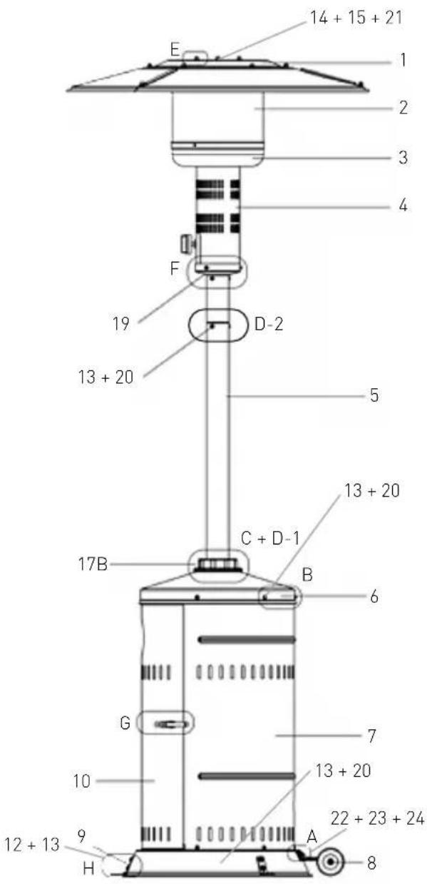
Patio heater part:
| Item No | Description |
| 1 Reflector assembly | |
| 2 Burner | screen |
| 3 Lower | tray of burner |
| 4 Lower | screen cone as- sembly |
| 5 Post assembly | |
| 6 Housing lid | |
| 7 Rear panel of housing | |
| 8 Wheel | |
| 9 Base | |
| 10 Door | |
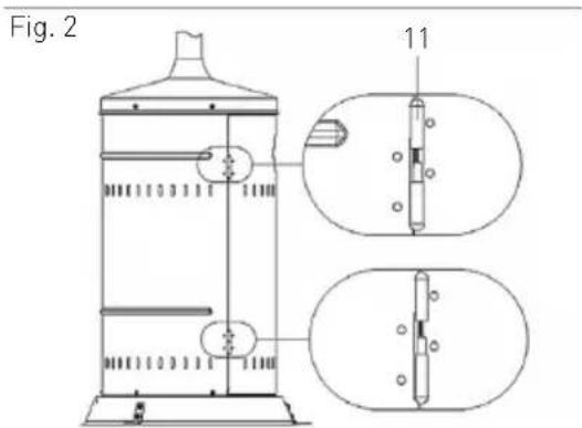
| 11 Hinge | |
| 12 Assembly Bolts M5x10 | |
| 13 Washers M5 | |
| 14 Bolts M6x8 | |
| 15 Wing Nut M6 | |
| 16 Lock | |
| 17 Plastic cover | |
| 18 Inner pipe | |
| 19 Igniter | |
| 20 Assembly bolts M5x12 | |
| 21 Washer M6 | |
| 22 Bolts M8x12 | |
| 23 Washer M8 | |
| 24 Nut M8 | |
| 25 Bolts M6x12 | |
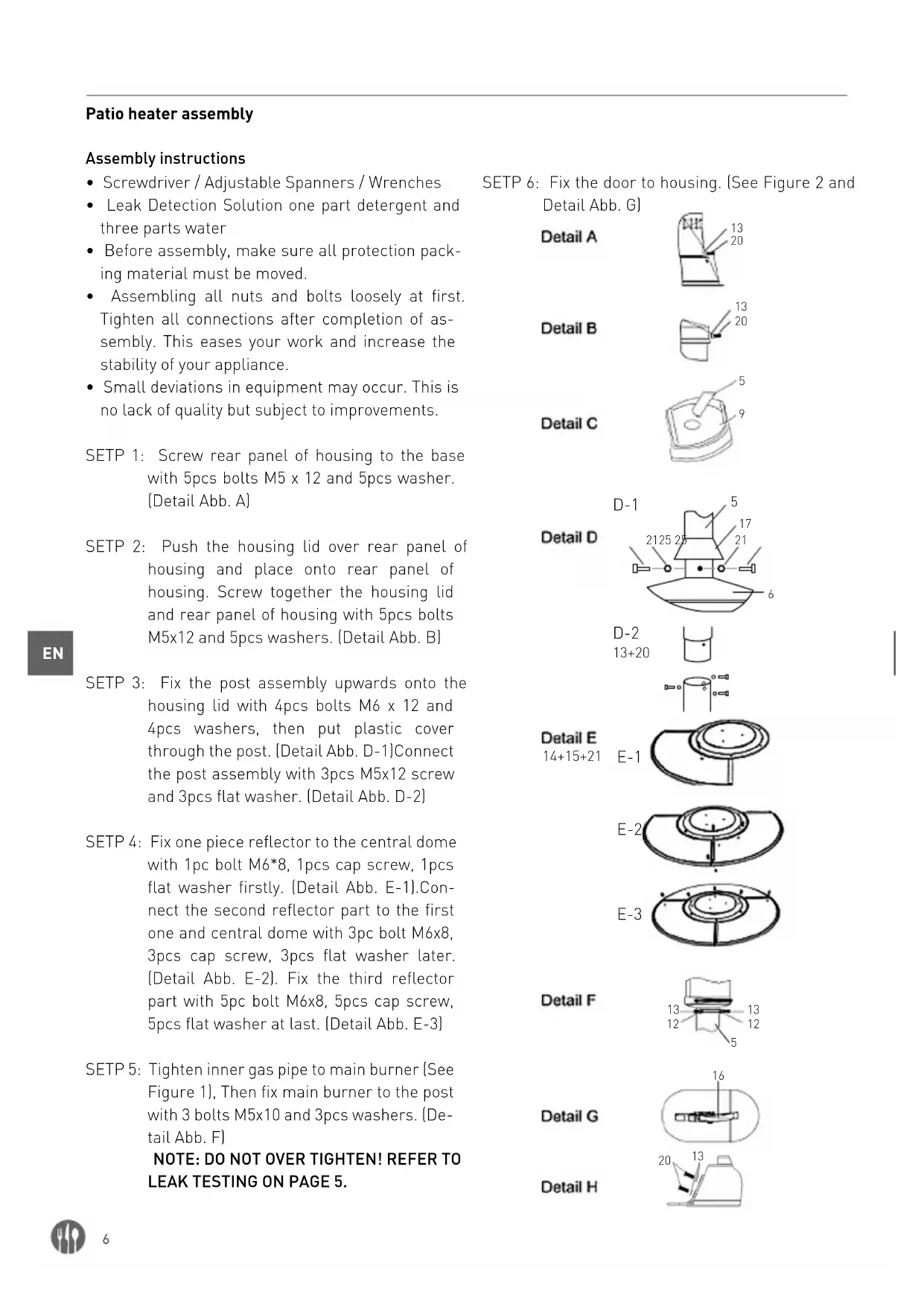
Patio heater assembly
Assembly instructions
- Screwdriver / Adjustable Spanners / Wrenches
- Leak Detection Solution one part detergent and three parts water
- Before assembly, make sure all protection packing material must be moved.
- Assembling all nuts and bolts loosely at first. Tighten all connections after completion of assembly. This eases your work and increase the stability of your appliance.
- Small deviations in equipment may occur. This is no lack of quality but subject to improvements.
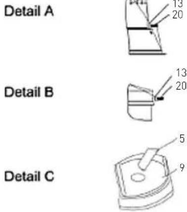
SETP 1: Screw rear panel of housing to the base with 5pcs bolts M5 x 12 and 5pcs washer. (Detail Abb. A)
SETP 2: Push the housing lid over rear panel of housing and place onto rear panel of housing. Screw together the housing lid and rear panel of housing with 5pcs bolts M5x12 and 5pcs washers. (Detail Abb. B)
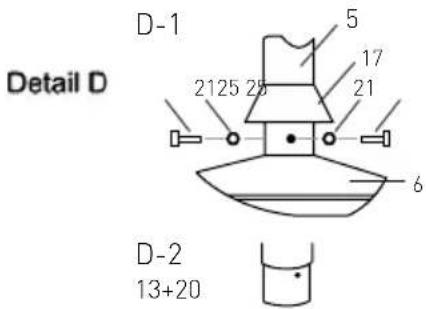
SETP 3: Fix the post assembly upwards onto the housing lid with 4pcs bolts M6 x 12 and 4pcs washers, then put plastic cover through the post. (Detail Abb. D-1)Connect the post assembly with 3pcs M5x12 screw and 3pcs flat washer. (Detail Abb. D-2)
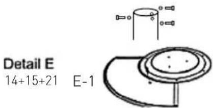
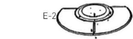
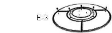
SETP 4: Fix one piece reflector to the central dome with 1pc bolt M6*8, 1pcs cap screw, 1pcs flat washer firstly. (Detail Abb. E-1). Connect the second reflector part to the first one and central dome with 3pc bolt M6x8, 3pcs cap screw, 3pcs flat washer later. (Detail Abb. E-2). Fix the third reflector part with 5pc bolt M6x8, 5pcs cap screw, 5pcs flat washer at last. (Detail Abb. E-3)
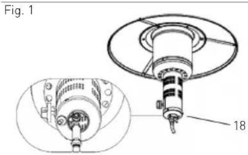
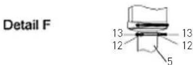
SETP 5: Tighten inner gas pipe to main burner (See Figure 1), Then fix main burner to the post with 3 bolts M5x10 and 3pcs washers. [Detail Abb. F]
NOTE: DO NOT OVER TIGHTEN! REFER TO LEAK TESTING ON PAGE 5.
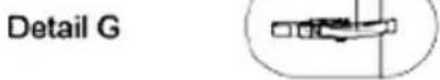
SETP 6: Fix the door to housing. (See Figure 2 and Detail Abb. G)

Optional base stand
Base stand assembly parts: 6pcs bolts M5 x 12 and 6pcs washers for base stands and base.
Attach 3pcs stands to the base.
Buy suitable hook bolts or rawlbolts from your lo
cal market to insert them into the ground or floor through base stand holes for this appliance stability. (See Figure 3)
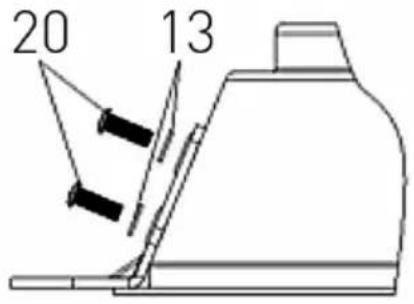
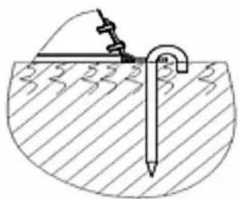
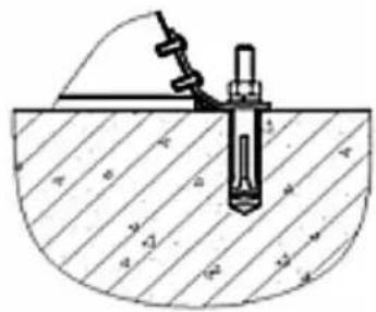
Fig. 3
Optional wheels
Wheels assembly parts: 2pcs bolts, 4pcs washers and 2pcs nuts for wheels assembly.
Collect wheels parts together and fix wheels to the base. (See Figure 4)
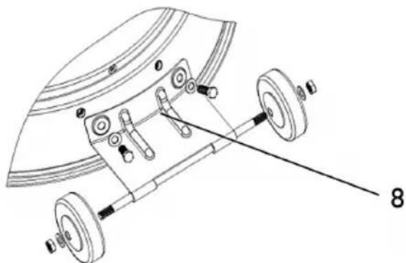
Fig. 4

Operating instructions
Before first use and after every gas cylinder change, gas delivery system must be purged of air before igniting! To do this, turn the control knob counter-clockwise to the pilot setting. Press knob in and hold for 3 minutes before attempting ignition.
To light the pilot
- Check all connections prior to each use.
- Turn on main gas supply.
- Press to turn control knob counter-clockwise to PILOT, see right photo.
- Hold knob depressed, press IGNITION button repeatedly until pilot flame is lit, then continue to hold the knob depressed for 10 seconds until the pilot remains it after releasing knob.
- If pilot fails to ignite or alight, press to turn knob clockwise to OFF and repeat.

To light the patio heater
- The pilot should be lit and the knob set to PILOT.
- Press the knob 3mm and turn anti-clockwise to HIGH.
- When mesh glows lit, turn knob clockwise from HIGH to LOW as needed.
Note: The burner may be noisy when initially turned on. To eliminate excessive noise from the burner, turn the control knob to the pilot position. Then, turn the knob to the level of heat desired.
Re-lighting
Note: For your safety, Control Knob cannot be turned OFF without first depressing Control Knob in PILOT position and then rotating it to OFF.
- Turn Control Knob to OFF.
-
Wait at least 5 minutes, to let gas dissipate, before attempting to re-light pilot.
-
Repeat the "Lighting" steps
To extinguish
- Hold knob depressed & turn the knob clockwise to 'OFF'
-
Close the valve of the gas cylinder or the regulator after use.
-
Allow this appliance to cool before moving. Note: After use, some discoloration of the emitter screen is normal.
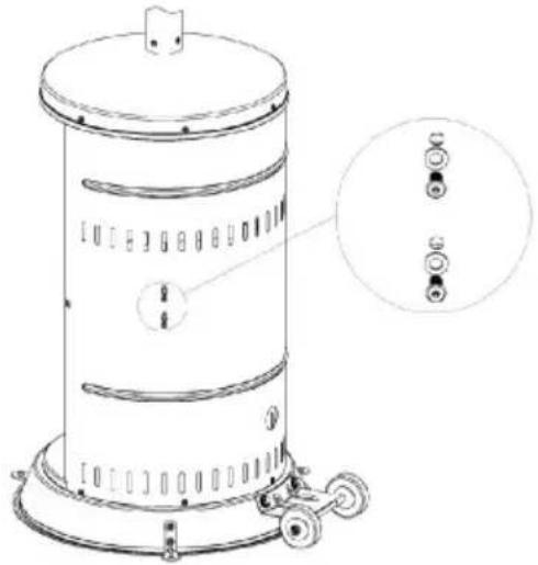
Leak testing

The gas connections on this appliance are leak tested at the factory prior to shipment.
This appliance needs to be periodically checked for leaks and an immediate check is required if the smell of gas is detected.
Make a soap solution using 1 part of liquid dish-washing soap to 3 parts water. The soap solution can be applied with a soap bottle, brush, or rag to the leak tested points shown in the figure above.
- The valve of the gas cylinder should be in the OFF position at this point of the leak test. Once the soapy solution is applied to the gas connections, the valve of the gas cylinder needs to be turned to the ON position.
- Soap bubbles will begin to form in the soapy solution if a leak is present.
- In case of a leak, turn off the gas supply. Tighten any leaking fittings, then turn the gas supply on and recheck.
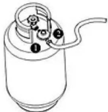
Leak Test Point ①②
Gas requirements
- The pressure regulator and hose assembly to be used must conform to local standard codes.
- Never use a gas cylinder with a damaged body, valve, collar, or foot ring.
- A dented or rusty gas tank may be hazardous and should be checked out by a gas supplier.
-
Never connect this appliance to an unregulated gas source.
-
When the appliance is not in use, turn the gas cylinder OFF.
Always perform a leak test on gas connections whenever a cylinder is connected. If bubbles form in the leak test solution, do not use. Never use a flame to test for leaks.
Connecting to a gas cylinder
- Recommend to use 9kg gas cylinder or refer to your gas supplier for suitable gas cylinder.
- Approved gas regulator is used according to appliances categories and countries listed in data plate. Approved flexible hose would be changed when the national conditions require it & consult the local regulations, these may differ.
- Warning: assembly of the tubing must be conducted by some qualified tuber of destination countries.
Refer to your gas supplier for instructions on the use of your gas cylinder. -
Only change gas cylinders outdoors or in a well ventilated area away from naked flames and any other source of ignition.
-
The gas cylinder must always be used in an upright position.
- Close the heater control knob by turning fully clockwise.
- Close the gas cylinder tap and then attach the regulator onto the gas cylinder.
- Tighten all connections firmly and with a spanner where appropriate. The cylinder should be located on the cylinder base.
- The gas cylinder must be fixed by cylinder belt, which is inside the housing, while installation.
- Check for leaks at all joints using soapy water. If a leak is found, tighten the joint and then re-test.
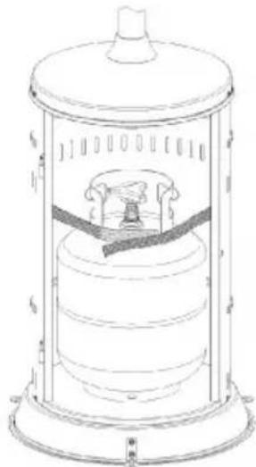
Securing the gas cylinder
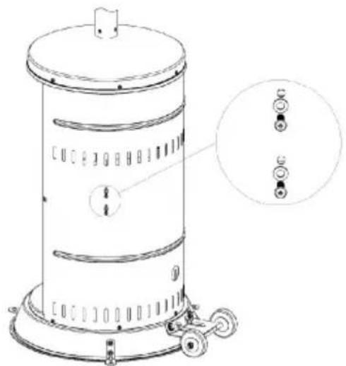
Fix both brackets of Velcro tapes onto the base using 4pcs M6*12 bolts, M6 washer and M6nuts.
- Position a gas cylinder inside the tank housing.
- Connect the gas cylinder with a regulator. Please refer to the instructions attached with the regulator on how to connect a regulator with the gas cylinder.
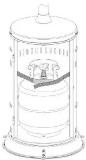
- Stick Velcro tapes together as above photo illustrated. The tapes must be in a proper tightness for the gas cylinder.
Caution: Please take care that the Velcro tapes. DO NOT strain the regulator assembly.
Important safety rules
For use outdoors or in amply ventilated areas. An amply ventilated area must have a minimum 25% of the surface area open. The surface area is the sum of the walls surface
The use of this appliance in enclosed areas can be dangerous and is PROHIBITED.
Children and adults should be aware of the high operating temperatures of areas above the post when operating this heater. Children should be carefully supervised when in the vicinity of the heater.
NEVER hang anything, including clothes or any other flammable items, on this heater.
DO NOT operate this heater unless it is fully assembled with its reflector in place. Respect the minimum clearances from combustible materials.
The length of the gas hose may not exceed 1,5 meters.

EN
Maintenance
To enjoy years of outstanding performance from your heater, make sure you perform the following maintenance activities on a regular basis:
- Keep exterior surfaces clean.
- Use warm soapy water for cleaning. Never use flammable or corrosive cleaning agents.
While washing your unit, be sure to keep the area around the burner and pilot assembly dry at all times. If the gas control is exposed to water in any way, DO NOT try to use it. It must be replaced.
Airflow must be unobstructed. Keep controls burner and circulation air passageways clean. Signs of possible blockage include:
Gas odor with extreme yellow tipping of flame. -
Heater does NOT reach the desired temperature.
-
Heater glow is excessively uneven.
- Heater makes popping noises.
- Spiders and insects can nest in burner or orifices. This dangerous condition can damage the heater and render it unsafe for use. Clean burner holes by using a heavy duty pipe cleaner. Compressed air may help clear away smaller particles.
- Carbon deposits may create a fire hazard. If any carbon deposits develop, clean dome and engine with warm soapy water.
Note: in a salt-air environment (such as near the sea), corrosion occurs more quickly than normal. Frequently check the corroded areas and repair them promptly.
Servicing
-
Please consult your local dealer for servicing this appliance and replacement of its parts. The servicing of the appliance shall be carried out only by authorised personnel.
-
Caution: do not use unauthorized parts or components for this appliance, only use original equipment replacement parts and components. The use of unauthorized parts or components will void the warranty and can create an unsafe condition.
Storage
Between uses:
Turn control knob OFF
Turn gas cylinder OFF
Store Heater upright in an area sheltered from direct contact with inclement weather (such as rain, sleet, hail, snow, dust and debris).
If desired, cover to protect exterior surfaces and to prevent build up in air passages.
Note: Wait until heater is cool before covering.
During periods of extended inactivity or when transporting:
Turn control knob OFF.
Disconnect gas cylinder and move to a secure, well ventilated location outdoors. DO NOT store in a location that will exceed 50^ .
Store heater upright in an area sheltered from direct contact with inclement weather (such as rain, sleet, hail, snow, dust and debris).
If desired, cover heater to protect exterior surfaces and to prevent build up in air passages.
Note: Wait until heater is cool before covering
CAUTION: DO NOT USE UNAUTHORIZED PARTS OR COMPONENT FOR THIS APPLIANCE. ONLY USE ORIGINAL EQUIPMENT REPLACEMENT PARTS AND COMPONENTS.
To retract the heater (272701 only)
Retracting the heater makes storage much easier. Loose the plastic screw [17] properly. Pull up the main post vertically until it encounters housing lid. Turn the main post clockwise and lower it until it has reached the desired level. To lock the main post on the desired level pull up the main post just
a little and turn it counter clockwise. Then lower it until the main post stands on its screws. Tighten the plastic screw to keep the heater stable.
Note: Mind your head. Wait until heater is cool before retracting.
Troubleshooting
| PROBLEM AND THIS CONDITION | Cylinder valve is closed Open valve | |
| Blockage in orifice or pilot tube | Clean or replace orifice or pilot tube. | |
| Air in the gas line | Open gas line and bleed it (pressing control knob in) for not more than 1-2 minutes or until you smell gas. | |
| Low gas pressure | Replace propane gas (disposable) cylinder with a new cylinder | |
| Igniter fails | Use match to light pilot (with match holder, see picture**); obtain new igniter and replace | |
| Pilot won't stay lit | Dirt build up around pilot Clean | dir t from around pilot |
| Connection between gas valve and pilot assembly is loose | Tighten connection and perform leak test | |
| Thermocouple is not operating correctly | Replace thermocouple | |
| Burner won't light | Gas pressure is low | Replace propane gas (disposable) cylinder with a new cylinder |
| Blockage in orifice Clear blockage | ||
| Control knob is not in "ON" position | Turn control knob to "ON" position | |
| Burner flame is low Note: Do not operate heat-er below 5°C (40°F) | Gas pressure is low | Replace propane gas (disposable) cylinder with a new cylinder |
| Outdoor temperature is greater than 40°F and tank is less than 25% full | Replace propane gas (disposable) cylinder with a new cylinder | |
| Supply hose is bent or kinked | Straighten hose and per for m leak test on hose | |
| Control knob is fully " ON" | Turn control knob to " OFF", let cool to room temperature and check burner and orifices for blockage | |
| Emitter glows uneven Note: Bottom 1 inch of emitter normally does not glow | Gas pressure is low | Replace propane gas (disposable) cylinder with a new cylinder |
| Base is not on a level surface Place heater on a level surface | ||
| Heater is level Clean burner | ||
| Carbon build-up | Dirt or film on reflector and emitter | Clean reflector and emitter |
| Thick black smoke Blockage | in burner | Turn control knob to "OFF", let cool to room temperature and remove blockage and clean burner inside and outside. |
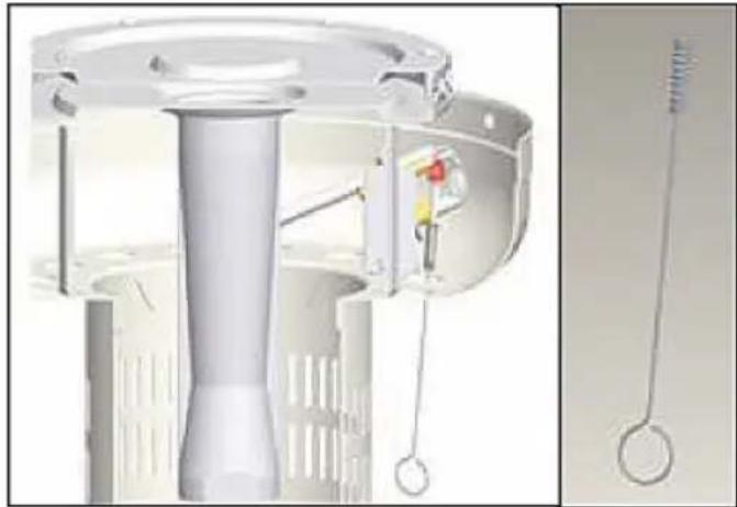
If for some reasons your ignition fails to deliver a spark, the heater can be started by inserting a lit match using supplied match holder through the burner hole (see left photo) while pushing the control knob in the "PILOT" position.
IN THE EVENT OF ANY PROBLEM, PLEASE ALWAYS CONSULT YOUR LOCAL DEALER.
Warranty
Any defect affecting the functionality of the appliance which becomes apparent within one year after purchase will be repaired by free repair or replacement provided the appliance has been used and maintained in accordance with the instructions and has not been abused or misused in any way. Your statutory rights are not affected. If the appliance is claimed under warranty, state where and
when it was purchased and include proof of purchase (e.g. receipt).
In line with our policy of continuous product development we reserve the right to change the product, packaging and documentation specifications without notice.
Discarding & Environment
When decommissioning the appliance, the product must not be disposed of with other household waste. Instead, it is your responsibility to dispose to your waste equipment by handing it over to a designated collection point. Failure to follow this rule may be penalized in accordance with applicable regulations on waste disposal. The separate collection and recycling of your waste equipment at the time of disposal will help conserve natural re
sources and ensure that it is recycled in a manner that protects human health and the environment. For more information about where you can drop off your waste for recycling, please contact your local waste collection company. The manufacturers and importers do not take responsibility for recycling, treatment and ecological disposal, either directly or through a public system.
PoiKJIoueHne ra3oBOro 6aJIIOHa
- PekomeHnyetcnaNoB30BaTb ra3OBbI 6aIIoH 9Kr nn 6aIIIOH, pekomeHIOBaHHbI NOCTaBUNKOMra3a.
- IcnoJb3yETcra Odo6peHHbI peYnTOp ra3a COOTBcTCTBm C KATEropnM yCTpoNCTB n CTpaHAMn, yKa3aHHbIMn B NaCnOptHO TabnUKe. Odo6peHHbI r6kN m JnaHr cJeDyET 3ameHATb B COOTBcTCTBm C Tpe6oBaHnMn HaunOHalbHbIX perlAmeHTOB IMecTHbIX peIamEHTOB, KOtOpbIE MOryT OTnUaTbcR.
- PnpdynpexkdeHne. C6opka Tpy6 doJxHa ocUeCTBnTbCRA KBaINΦuNpOBAHHbIM cneuaJIInCTOM B COOTBeTCTByIOSeI CTpaHe.
-
RykoBoDCTBO no 3KcNlyatauHra30BOro 6aIloHa ДоЖен NOCTaBHTb NOCTaBUnK ra3a.
3aMeHnTe ra3OBbI 6aJIIOH Ha OTKpbITOM B03- DyXe, B XopoIo BeHTNIpyEMOM MecTe, BdJI N OT OTKpbIToRo PImaMeHN IpyrNX NCTOCHNKOB BOCPnAmHeHn. -
Ra3OBbI 6aIIIOH IOJIKeH 3KcNlyaTInpoBaTbcr Nc-KIIOHTeBHO B BepTNKaIbHOM NOJIOKeHN.
3akpynte pyky peynilpoBkn oborpeBaTeJn, noBopauHBa e do ynpa no yacoboi cTpeKe. - PerekpoTe BeHTnIb ra3oBoro 6aIINoHa n npncOeHNHTe K Hei peDyKTop.
Xopo0o 3aTAHnTe coeINHeHHn, nCNoJIb3yInTe KJIouB CJIyuae Heo6xOdUmocTn. NocTaBbTe 6aI- loH Ha OCHOBaHN. - Пи установке ra30воро 6алноа erо Heo6хODIMO npinkpenTb C nOMOьpo peMHЯ BHyTpNi KOpnyca.
- ПоберпгБе Вс coeHHeHЯ Ha rePMeTnUHocTb, И спользУЯ BODу CMbIOM.Еси Bbl ObHApYKHTe yTeKY, 3aTЯнITE coeHHeHЯ И пobeДNTe пobepKy eш pa3.
3aunTa ra30BbIX 6aJIIOHOB
-Прикpeniteоба конца lentы Ha Лпунчke Koc-HOBaHnO C nOMOuIb 4 BnHTOB M6*12,waN6M6 n raeK M6.
- IomeCTIte ra3OBbI 6aJIIOH B KOpNyc KOHTeHepa.
- PoiocoeHnHTe ra3OBbI 6aJIIOH K peDyKTOpy. IpoHTte HnCTpykU, npJlaRaemble K peDyKTOpy, yTo6bl npOBepuTb, KaK PoiocoeHNHTb Ra3OBbI 6aJIIOH.
3akpennte IInnyk, KaK noka3aHO Bblwe. JeHTbI DOJXHbI 6blb 3akpenJIeHbI TaKIM 06pa3OM, YTO-6blra3OBbl 6aIIIOH 6bl HaJeXHo 3akpenNeH.
Ipimechane: He 36ydbTe coxpaHnTb IInnyuKn. HE 3aRpykaTe peDyKTop B c6ope.
RU
OchOBhble npaBnla TexHKn 6e30nacHoCTn
IINcnoJb30BaHnHaOTKpbITOM Bo3dyXe INN B XopoOIO npOBETpNBaEmBX NOMEueHnx.
MecTo C xopoWei BeHTnIaIeN DoJIxHO 6bITb OT-KpbIto KaK MInHmym Ha 25%.
3TO OTHOCHTCA K 25% OT o6uE NOBEPXHOCTN CTEH.
IcnoJb3OBAHne 3Toro 06OpyIOBaHnB 3aMKHyTom npoctpaHCTBe MoKet 6bIb onacHo n 3APELEHO.
IeTN B3pOcNbIe IOnXHbI 6bITb OCBeDOMneHbOBbICOKo TEMnepaType HAd CTOn6B MKNIOUeHHOR06OrpeBaTeJI. DeTei, HaxOJaUncB HENOCPeJCTBeHHOH 6JIIN3OCTN OT HaPeBaTeJI, HYKHO BHIMaTeJIbHO KOHTPOIpOpBaTb
Ha o6orpbeBateJe HNKoIa HeIb3a HnUero Be- WAtb, BkIOuOa OeKdy NIn JERKOBCnAmEHO- UneCnpeDMeTbl.
HE nCnoJb3yIte o6oRpeBaTeIb, noka OH He 6ydet NOnHOCTbIO CO6paH I OTPaXaTeIb NOMEuEHN HcBOe MeCTO. Co6JIoJaIte MInHIMaJIbHOe paCtToHnE OT ROpUOx MaTePnaIOB.
IINHa r3oBOrO npoBoJa He MoKeT npeBbIaTb 1,5M.
TexHnueckoe o6cnyKuBaHne
YTo6bHa npotjXeHm MHornx neT paOBAtbcn OTnueHon pa60To n 6oRpeBaTeIa, peryIpaHO BblnoHnYe cneNyUoIe DeIcTBnNo TexHnueckomy 6cbnyKnBaHHIO:
- PoiDnepKuBaIeB uHcTote BHeuHne noBepxHocTn.
-ДяоунгИСПОЛБ3УTe TEПЛYIO BODy C MblOM. HNKOrda He IcNoIb3Ute JERKOBocnlaMeHЯIO-UIneCЯи eKne YNCTaUne cpeDCTBa. - 06paaIte BHNMaHHe, yTo6bI BO Bpemr OunchKn ycTpoiCTBa He HAMoUHTb npocTpaHCTBa BOKpyr ropeKN nn KOHTpoJIbHOrO nlaMeHN. B cnyae KaKoro-Jn6o KOHTaPeYJrTopa ra3a C BoIo, HE npo6yIte ero nCNoJIb3ObaTb. Ero cneJeYETaMeHNTb.
He nepekpbyaIte noTOK BO3dyxa. IOpIepKuBaIte B uNCTOTE ynpabLeHne, rOpEKNy N KaHaJIbI CuNPkyJauCnB03dyxa. PpN3HaKn BO3MOxHOn 3a-KyIopKn BkIIOUaIOT:
3anaxra3aN60nbune,yeMobbHNOXeIbte 0KoHuaHnIpaMeHn.
- oborpbebatenb HE docturaet hyxhoi temepa-typbl.
- HakaonoborpeBaTeIaHepaBHomepHbI
- 06orpeBaTeIb n3daeT noTpeckKBAIOUne 3Bykn.
- Pnykn Hacekombie Moryr rHe3nTbcB R opeKe nn OTBepctnx. 3To MoKet NOBpeNTb 6oTgeBaTeJIb nn npNBecTN K TOMy, yTO nM 6ydet onacHO noIb30BaTbcR. OunuAte OTBepCTNra RopeKn, nCnoJb3yra HaJeKhbl INHcTpymeHT dJa ouNCTKn npBOOob. MeKne uactNu bMOxHo ydaJIb T CKaTbIM Bo3dyXOM.
- Harap moxket co3daTb onaCHOCTb BO3HnKHOBEHn noXapa. Ecnn noBRTcKaKne-Jn6o OTnoXeHn caXn, ouNCTte Kynon n DvraTeIb TeIIOB BODOn CMbIOM.
3aMeuHHe: B cpeE C BbICOKoC oJeHoCTbIO (Ha npmep, Ha Mope) Kopp03nI pOncXoJNT 6bICTpee, Yem 06bIyHO. YaCTO npOBepaTe KoppoDnPoBaHHbIe yUaCTKN I HeMeJIeHNO IpOBoJNTe Heo6XoDNMbI peMOHT.
CepBnC
- IoxaanyiCTa, o6paTntecb K MeCTHOMy nOCTaunKy OTHOCHTeNbHO TexHNueCKOrO 6cnyKbAHnY cTpoNCTBa N 3aMeHb erO qacte. TexHNueCKoe 6cnyKbAHne yCTpOInCTBa dONXhbl npoBOdntb NCKJIOnHTeNbHO yNoJHOMoEHhbIe JNuca.
3ameuHHe: He noIb3yItecb HeopnHaJIbHbIMn qactmN n DetanMn. IcnoJb3yIte Tolbko opnHaJIbHbIe 3aIacHbIe qactn N KOMNoHEtbl. IcNoJb3OBAHne HeopnHaJIbHbIX qacte Nnn KOMNoHEtOB npIBeTe K aHHynpoBaHIO rapaHTn N MoKet 6bITb OaChbIM dIra Notpe6nteJe.
XPAHEHNE
B nepepbIbax, kOrda yCToPcTBo He nCNoJIb3YeTeC: NOBepHnTe pyuKy ynpaBHeNn B noJoxKeHne OFF. 3AKPYTITE ra30b6aIIIOH.
XpaHnte o6oRpeBaTeIb B BeptnKaIbHOM nOLOKeHnn, B MeCTe, rIe OH He NoBBePraEtc Bo3DeiCTBIO He6laIopnpTbIX NOrOhbIX ycNoBn [Ha npImep, Doxbl, MOKpbI cHer, rpaI, CHer, nbIb nnrpr3b]. B cnUyae Heo6xOIMocTn HakpoiTyeCTpOJCTBO dJa 3aunbl BHeuHnx NobepxHocte I dJa PpeIoTbPaueHnnaCopeHnKanAoB cInpKyJIaCnN BO3dYxa.
BHHMaHHe: Npeed HaKpbItnem 6oBorpeBaTeJr, noDoxkndTe, noka OH octbIHeT.
Bcnyae 6oJee dIInTeIbHOro nepepbIBa HcNoIb30-BAHN yCTpOINCTBa INN BO BpeM TpaHCnOpTnpOBKn: NOBepHIne pyky peylnpOBKn B noLoXeHne OFF. OToeHNHe ra3OBbI 6aIIOnH n NomecHTte erO chapxN B 6e3oNaChOM MeCe C xopoWe BeHTnJIaueH. HE xpAnHe erO B MceTe, rIe Tempepatypa npebblaaet 50^
XpaHnte o6orpeBaTeIb B BepTnKaIbHOM noLoXeHNB MeCTe, 3aunuEHHOM OT He6laonpnaTHbIX nOrOdHbIX ycNoBn (HaNPmEp, DoxDb, MOKpbI cHer, rpaI, cHer, nbIb I rpy3b).
B clyuae Heo6xOJMoCTn HAKPOIte yCTpoiCTBO dIa3aunTbI BHeUHnx NOBepXHocTe N dIe IpeDoTbpa- ⅢeHnra 3acopeHnra KaHaNoB cIpKyJauuN Bo3dyxa.
BHHMaHHe: npeH haKpbItnem o6orpeBaTeIe noDoXkDnte, noka OH octbIHeT.
BHIMAHNE: HE NOJIb3YITECb HEOPINHAlbHbIMN YACTMNI JETAJMI. IcNoJIb3YIte TOJIb-KO OPINHAlbHbIE 3ANACHbIE YACTN KOMNOHEHTbl.
Ykpblne o6orpeBaTeIa (ToIbko 272701)
CklaabbaHne TeNIOBOrO 3oHTnKa 3NaHTeJIbHO 06-nerHaet erO xpaHHeHne.ДЯ 3TOrO HxKHo npaBnIbHO OCBo6OnIb PnactIKOBbI BnHT (17).NotAHnte BepTKaJIbHO rJaBHyIO CTOnKy, nOKa OHa He KocHeTcraAaHTHO KpbIshKn Kopnyca. NObepHnte rJaBHyIO CTOnKy no HaprabLeHnIO YacOBoN CTpeJKN I ONyCTInTe eE noka OHa He DoCTnIRET HyXHOrO yPoBHa.ДЯ TOrO, qTo6bl 3a6NoKupOBaTb rJaBHyIO CTOnKy Do HxKHorO yPoBHa, NotAHnte BBepx, a NOTOM NobepHnte npOTNB
yacobon CTpeKn. 3aTeM onyctnte e, noka rnaBnaCToikae He 6ydet cTOrb Ha CBOnx BnHTax. 3aTaNtepnnactMaCCOBbl BNHT, yTo6bl TeNIOBOI 3OHTNK 6bl CtaBnBhI.
3aMeuHHe: OcToPOxHo, 6epeRrTe rOIOBy. Ipeed NaIOM cKlaIbIbAHn, nOIOXdIte, noka o6orpeBaTeJIb OCTbIHet.
YcTaPaeHHe HeCnPaBHOcte
| ПОНБЛЕМВОЗМоЖ | НА ПИЧИHA PELSEЕНЕ | |
| He можно заочець контrolьно пламен | 3атян't вентлиь 6аллona. 0TKpyтinte вentлиь. | |
| Заблакорован bixiod ivii shilaig kontrolьно пламен. | Очирпite ivii zamehite bixiodhoe OTberpсITE ivii shilaig kontrolьно пламен. | |
| Воздух в ratовий установке. | ОTkpytnte ra3obuyu yctanobky u bivnyctnte hemhoro ra3a (нaximая ручу ретулрови) в чechени мбк. 1-2 minHyt ivii noka he novybctbye ra3. | |
| Hizskoe давлие ra3a. 3amehite 6alnoh (odnhopazobу) | i c npoapanom ha nobiy. | |
| He Dei'stebyet zaxinralka. | Icnpolb3yite cnilchki,чтобу zaxeyb kohtrolbhoe пламя; (дя заю пользуITE спесиалынй deprжателдя спчek(сm. рисунok**) Зakajite u yctahobite HObyIO 3axinralky. | |
| Контrolьно пламя rachatET | Bokpyr kontrolьно ratopelknck scollnilaceb griazb. Ouchstte | Te przib bokpyr kontrolьно ratelknk. |
| Прервано coeiniendne міжdu ra3obblm běntilne m uzylOM kontrolbno ratopelknk. | Затянite coeiniendne и провьte repermetnucnoctb. | |
| Терmonаheadapie na pabotaeTdoJxnbIM obpa3om. 3amehite | Teprmonapy. | |
| Горелka He zaro-paetcra | Hizskoe dablenie ra3a. 3amehite 6alnoh (odnhopazobу) | i c npoapanom ha nobiy. |
| Засорен bixiod ra3a. YctpanHite | ||
| Ручka perynipovbknke He haxoDITCBA INOLOXeHIN .ON". | Повернite ручka perynipovbknв в положене..ON". | |
| Пламя ratopelknck smilskom clamboe Bниманe: He nciplb3yüte oborpe-Batelпри tempepa-type nixke 5°C | Hizskoe dablenie ra3a. 3amehite 6alnoh (odnhopazobу) | i c npoapanom ha nobiy. |
| Tempeparatya npeblyaest 5 °C, a 6alnoh 3anonhen Mehee 25%. | Зamehite 6alnoh (odnhopazobу) c npoapanom ha nobiy. | |
| Гazobii shalaR n3oRHT ivii ckpyen BvIpramite shala | i npoberpbte repermetnucnoctb. | |
| Pryka unpaklenia yctahOBLeHa B maksimalmbhoe noLOXeHne .ON". | Повернite ручka perynipovbknв в положене..OFF",падждte,пoka harpebaTeB ocbyHet do komnathoj TempepaTpyb, a 3aTe m npovpebte, ch66b lopekna i BvInyckhble otbercstna He 6bln 6blokinpobahly. | |
| ОBGPeBaTeN He ropit paBnOmeHPO 3amuehanee: Hixxhiy uychtok 2,5 cm obiu-ho He nargpeBaTeCra. | Hizskoe dablenie ra3a. 3amehite 6alnoh (odnhopazobу) | i c npoapanom ha nobiy. |
| Освоганe He CTouT Na pOBhoi noBepxHoctn. Noctabe | Te oborpebaTeB na pOBhoi noBepxHoctn. | |
| ОBGpeBaTeN He ypaBHOBeWeHn BvIpramite oborpeBaTeB. | ||
| Harap Гязь и с两点 | Пи на оtraxketene и oborpebaTeNe. Ouchstte OTPaxketene | i oborpebaTeB. |
| Густо чьнь дым | Зakypорea ropenka. | Повернite ручka perynipovbknв в положене..OFF",падждte,пoka harpebaTeB ocbyHet do komnathoj TempepaTpyb, полес Quero BOCSTAHOBite npoxodmoctb ropenknu ochstte eë chapuxu n BVHTpn. |

Ecn no kaon-TO npnue He nckpa 3axnraHnHe NoBnaeTc, oBorpeBaTeIb MoXHO BKNIOHTb, BCTaBnA CnUky B OTBepCTne RopeKn C NOMOuTo npnaraemoro DePxAteIa DnA CnUeK (cm. oToTOrpaΦnIO cNeBa) n OndOBpeMeHHo NOBopauHBa pykny perynipOBKn B noJoxHne .PILOT".
B clyae kaKx-1n6o npo6IeM, Mbl npocm CBA3aTbca C MeCTHbIM NocTaBUnKOM.
RapaHTn
JIb6a HeoJekKa IINI NOnOMKa, KOTopaB BJeUe3a co60n HnnpabInbHyu pa6Otu yCTpoNCTBa, KOtopa8ydt BbIBNeHa B TeueHne nepBOrO rOda O TaTbI NOKynK, 6yTeYcTaPHeHa 6ecnPaTHo, INn Xe BCE yCTpoNCTBO 6yTe3aMeHEHO HOBIM, ECNI OHO 3KcNpyATnpOBaNoCb n 06cnyXnbALocb cOrnaCHO HnCTpyKUnn No 06cnyXnbAHnIO n He NCnoB3OBANoCb HnnpabNbHo, INN B pa3pe3 C Ha3NaueHem. DaHHoe NpIoXeHne Hn KoE Mepe He HApYsAet INhIx npAB Notpe6nteJra, IN3IoXeHHbx B 3aKOHO
daTeIbCTBe. B cnyae 3aBHeHn ycTpoiCTBa B peMoHT nHa 3aMeHy B paMKax rapaHTn, cNe dyETyKa3aTb MeCTO n DaTy NOKyPkN ycTpoiCTBa n npNoXNTb CcET, nII NeKOBYIO KBNTaHciHIO.
CorgaHo HaWei NOJNTKe COBepHeCTBOBaHnHaIINx npOyKToB OCTabJIeM 3a Co60n IpaBO HaBBOD n3MeHEnB KOHcTpyKcNIO, yNaKOBky N B TexHNueckne npaMeTpbl, yKa3bIBaEmble B TexHueckOn dOKymeHTaCm 6e3 npedynpeXdEHH.
Yttnn3aunn n 3aunTa OKpykaUoien cpebl
B cnuyae BbIbOda o6OpyIOBaHnI 3 EKcnIyatauN, npOdyKT HeJIb3a yTUNI3nPoBaTb BMeCTe C dpYrIMN 6bITOBbIMN OTXoDAMN. PONb3OBaTeJIb HecET OTBeTCTBeHHocTb 3a nepeDaUy o6OpyIOBaHnI B COOTBcTCTByUOuN INyK TnpEma TexHnK 6bIBwe B yNoTpe6IeHN. HecobJIoJeHne BblIeYka3aHnHO IonoXeHnMoXeT npINBeCTn K HanoXeHnIO UTPa-foB B COOTBeTCTBnC DeIcTByUOuMn IpabnAmn B OTHOseHn YtUNI3aUIn OTxOoB. CeJIeKTHBhI c6Op n yTUNI3aUIn NCnoJIb3OBaHHoro o6OpyIOBaHnI CNOC6CTByIOT CoXpAHEnIO npIpOdHbIX
pecypcoB n obecneuBaHT peuPKyIaIIO TaKIM o6pa30M, KOtOpbI He BpeDeH IJIa 3DopOBbI n OKpykaOoSei cpebl. IJIa IOnlyeHnI DaONHInTeJbHO HΦOpMaUIN O TOM, rIe MoKHO OTDaTb NcNoJIb3OBAHHoe 6OpUdOBAHHe IJIa YTNlN3aUIN, 6bpatNTecb B MeCTHyIO KOMNaHnIO No c6opy OTxo-DOB. PpOn3BOJnteBn IMNOPTep He Hecyt OTBeTCTBeHHocTn 3a peuPKyIaIIO n Nepepa6OTky OTXoOB 3KOJIoRnuCeKn 6e3OpaChbIM CnOCobOM, KaK HeNocpeIcTBeHHo, TAK N B paMKax rOcyApCtBeHHo CNCTeMbI.
Euxapiotouneouayopaaoteauto npoiovHendi.iaBaoTe npooektikto npov eyxepio npiv auvdoettn ouakeun, npokieevou va npolaBete nOavn BbaBn nou mnpei va opeiIeai oe Iav- 0aouevn xpon.iaBaote iowc touc kavovmuoc aopaaleiac nou npooektikda.
Oδnyiες ασφαλείας
- Aut n ouokéun npénéi va xnpoumonoiéitai oε εξωτepikouc xwpouç n oε kaá aεpióμevo xwpo kal δev npénéi va εykaθiσatai n va xnpoumonoiéitai oε εσωτepikouc xwpouç.
AaaTeTn piAn aepiou eKaa aepizoEvoxwpo paKpia anEupkntc nnyec.
H piaan npenv va ano nkeuetal oE Ewepikouc xwpouc n e ka'aepizoevo xwpo. - H anoθnkeuon autnc tnc ouokεunç oε εωτερικό xwpo επιρεπειλ μóvo εav n φιαλn aερεou exi anoouvδεθεi kal aφaipεθεi ano tn ouokεun.
Mnv n ouokekun otav eival oE i n otav eival anevepyonoinpuevn kal dev exI KpuwoeI.
Mnv enixepnoe va kavte aalayec otn ouakeun onoiovdonote tpo. Mnv Bapetenv oxapa aktivoBoiaic, tov nivaka eEyxou n tov avaklaotnpa.
Mnv qpaZeTc onec aeploou tou nepBnaTOC tou piaInc.
H ouokeu npenvla ykataotaekai n pialn aepiou npenei va anoynkeutai oupwva touc tonikouc kavovioouc ykataotaonc puotowdavoumc. - Kλεισε τη Βαλβίδα στη φιάλn αερίου ἡσου ρυθμιστή πριν μετακίνησετε τη συσκεύπ.
Xpnouoie Tov tuno aepiou nou kaopizetai ano tv kataokuaotn.
O1 eiokeuec npenei va yivovtal ano Eeikumu evo npoomegaiko. - Σε πεπτωσιοχρού ἀνέμου, δώτε προσακή στην πεπτωσιοῦν ἐχει πάρει κλίση n Σωακεύή.
BεBaωθειτε οι n BaλBiδa ρύθμιονς ἐχει τοῦθετηθει σωσα τοι εἰναι σε θεσαν αλει touργήσει σωσα.
KlEioTe Tnv npoxn aepiou otn BaBbDaa tnc pfalnc aepiou n tou puOmuotn eTa tn xpnon.
Mnv xpnaonoiie t n ouakeun npiv dookmaote oAec tic ouvdoeic yia diappoe. - Σε πεπτωπ διαροής αερίου, n συοκεύν δεν πρέπειν αχρομούηθει και στην περτιωπ φωτιὰς, n napox ἀερίου πρέπειν αδιακόπει και n συοκεύν πρέπειν αξεταοτει και va διορθωθει πριν xρομούηουπθει ξάν.
- Eλεγχετε ηι σωλήνωσι n τον εύκαμπιο σωλήνα κάθε μήνα και κάθε φρός nou αλλάζετε κύλινδρο.
- H ωλνωπ n o εύκαμπος σωλνας πρέπειν αλλάσεται ευτός των προκαθορίαμενων διαστημάτων n ευτός ενός ἀτους. O εύκαμπος σωλνας δεν πρέπειν αυπερβαίνει τα 1,5 μέτρα σύμφωνα με το πρότuno EN16436: 2014.
H diatae n tou oaniva npenei va avikataotaeei npiv mnei oE leitoupyia n ouokun, eav unapxouv evdeiEic unepBoaiknC trBnC n opac,n av o ukauntoc oanva cival katotpauevoC. O oanva c avikataoanaC kaOpizetal ano tov kataokuaotn.
H 3epa npenei va eniEewpeitai npiv ano tn xpnon kal toulaiootov ia popa ka3e xpovo ano e1ikueuévo texviko. O auxvotepoc kaapiaouoc mnpoei va eivai eniB5nuevo
avaloya tic avaykcs. EivaI eitaktiko va kathetaiEa to diaepioa 5yxou, oI kauotnpcKai oI iodoik ukoopopiaac aepa.
Anevepyonoiote kai eleye aoeowc tn eepa ev upiotatai kana a no tca akoloh 0ec ouvthkEc:
Eav mupizciaepio kai ouvodueetal ano eyaan ekpon ano ktpivn olaoya ano tov kaou npa.
Eav tn 3epmuotpa 3e 4avei tn 0wotn 3epkoopaia. Mta 3epmuokpaa ukpotepn ano 5^ 8a npokaalei nepioipouevn poh 3epoTntac kai n oukeun dEv th a letoupynoe i owtá.
Eav n ouokεuñ kávei θópuBo σa va okaεi kátι, kaṭa tn δiapkeia tcn xphoc (o μikpòg θópuBoç okaiaμatoc εival φuoiλoyikóc òav oBnvεi n ouokεuñ).
- O puθμiαntc kal o εικαμπος ωλνας πεπειν αβρικονται ἔξω anò διαβρομες nou μnορειν ακονταψει καποιος kal aλθος, kal anò περioxn nou μnορειν unοστει ζημία σωλνας.
- Onoiobhnotepoopulakntnpacn aalnn npootateutikn ouokun nou apaipetial yia tn ouvtpnon tnc 8epmuotpacs npenei va tono8etn8ei gava npiv ano tn 8eitoupyia tnc 8epmuotpaç.
- Ta naiδiá kal oI evnλiεç npéneI va npoεiδonoinθouv yia tov kivduvo uynλnC θερμokpaiaç tcN επιφανεiac kal npéneI va npaμévouv μakpià yia va anopεuxθouv εykaúpata kal va πiαοuv φωτiá ta pouxa touc.
- Ta μικρά παίδιὰ καὶ τα κατοικίδια ζώα πρέπειν αἰ ἐπιβλέπονται ὄτavirus Bpiokovtai στην περioxh tcns θερμάστρaς.
- Ta pouxa n àλλa εύφλεκτa uλικα δεν πρέπει va κρέμονται στη συσκεύн kal δεν πρέπει va tonoθετούνται napω n κόνται στη συσκεύн.
Mnv tonoTheTeiE kal mnu otnpizetE avtkeiEv aOn OuaKeu. Oioeva uIka n avtkeiEv aou aoNkEvotai kato kovta on OuaKeuun npoei va eKTeouv oE aktivoBoAoEvn 0epoTnta kal npoei va unootouv oBapn BaaBn.
Mn xpnoiopoiei te kai un aoonkeu ete uokk ta uikovt a on ouokun.
Mnv k z e aepoluuma kovt a tny ouokueh otav elal oE I oupyia.
- Διαπρείτε πάντa anοσαση τουλαχιοτον 0,9 μέτρων anο εύφλεκτa uλικά.
- Tonoθετειε nαντa tn σοκευήσε οε σαθερή επιηδόn επιφάνεια. 'Evac kaλα αεριζόμενος xωρος πρεπειν ἀ εχει τουλαχίοτου 25% ελεύθερο εμβαδόν επιφάνειας. To εμβαδόν επιφάνειας εieval to ὅθροισμα tcns επιφάνειας των τοixων.
- O εγxutnpac σε autn tn σωκειδεν εival anoonωενος kal ouvapμoλoyεitai μóvo anotov kataokεuaotn. Autn n σωκειn anayopειεtai va μεtatpèπει μia niεan aεpiou σε ἀλλη πεση.
Mn ouvodetov kulivopaoepiou aneuethiaoctn ouokun xwpicpuotn.
- O kúlvöpoc aεpiou npènεi va στερεωθει με tov iμávτa kuλivöpou, o onoioç Bpiokετai μèσa στο πεpißλnμa, kalà tnν εγkaṭàσaón.
PpO8λeNoεvn xρησ
H ouakeun npoopizetai yia enayyEaatikn xpon kal npenla xnpaonolitai movo ano etiku- u evno poowniko.
H ouakeun eival oxediaouevn yia 0epuavon mov oE EwTepiKo n ka aepizoevo xwo. OnilaOn note aan xpnon npopei va npokaolei BbaBn otn ouakeun n tpaumatoo.
H xpnon tnc ouokekunc yia onoiovdonote aallo okoono 0ewpeital kakn xpnon tnc ouokekunc. O xpnotnc eival anokklaotika unuthetauvoc yia tnv akataaann xpnon tnc ouokekunc.
KataooyocεAptnμatwv
EuvaipoIoynon 0eepaotpa
Odyie ouvapmooynonc
KaataBidi/PuOmuZoEva Kλeioia/Kλeioia
- i u a avixveuong diappoNC, eva eepoc anoppu-navtuko kal pia eepn vepo
Piv ano tn ouvapmooynon, BεBaωθεitε oti oλa ta uλiká ouokεuαoiac exou apαipεθi.
- Suvapuoynte npwa xalapa ola ta naEmuadia kal tic Bioc. ZpiEte oec tic ouvdoecic mTa nV ooknwn tnca uvaupoaynonc. Eto dukolveote otnv epyaia oac kal auavetal n otaepo-tnta tnc oukeunc oac.
Evexetai va unapxouv ukec anoklaoeic otov Egonlao. Auto dev opeiEeTal eKakn noIotna, aaa oBtioeic.
BHMA 1: BldwTe nviow eniupaveia nepiBnmuatoc 0tn Baon tC 5 BiEc M5 x 12 kai Tc 5 poEeAEC. [x. AenToupeiaac A]
Hendi Food Service Equipment GmbH
Ehring 15
Hendi Food Service Equipment Romania S.R.L.
Str. 13 decembris 94A, Hala 14
Braşov, 500164, Romania
Tel: +40 268 320330
Email: office@hendi.ro
PKS Hendi South East Europe SA
5 Melsovou Str.
18346 Moschato, Athens, Greece
Tel: +30 210 4839700
Email: info@pks-hendi.com
Hendi Italia S.R.L.
Via Leonardo da Vinci 4
39100 Bolzano (BZ), Italy
Tel: +39 800 727 438
Email: office.italy@hendi.eu
Hendi HK Ltd.
1208, 12/F Exchange Tower
33 Wang Chiu Road, Kowloon Bay, Hong Kong
Tel: +852 2154 2618
Email: info-hk@hendi.eu
FindHendi on internet:
www.hendi.eu
www.facebook.com/HendiToolsforChefs
www.linkedin.com/company/hendi-food-service-equipment-b.v.
www.youtube.com/HendiEquipment
- Changes, printing and typesetting errors reserved.
- Änderungen und Druckfehler vorbehalten.
-Wijzigingen en drukfouten voorbehouden. - Producent zastrzega sare prawo do zmian oraz będow drukarskich w instrukcji.
- Variations et fautes d'impression réservés.
-
Errori di cambiamenti, di stampa e di impaginazione riservati.
-
Drepturi rezervale cu privire la modificari si gresei de imprimare.
-3mehenHn, neaTHn BepCTKn 0uN6Kn 3aunuHbI.
-Me enipuaen aayaw,aaBw ekwnoncn katoxioeoiac.
-Zmeney, chyby tisku a sazby vyhrazeny. - Spremembe, tiskarskih napak ter pridrzane.
- A valtoztatások, a nyomtatási és a szedési hibák jogát fenntartuk.
-Zadrzano pravo na izmjene, pogreske u ispisu tiskarske pogreske.

- Safety regulations
- Intended use
- Part List
- Assembly parts supplied:
- Patio heater assembly
- Assembly instructions
- Optional base stand
- Optional wheels
- Operating instructions
- To light the pilot
- To light the patio heater
- Re-lighting
- To extinguish
- Leak testing
- Gas requirements
- Connecting to a gas cylinder
- Securing the gas cylinder
- Important safety rules
- EN
- Maintenance
- Servicing
- Storage
- To retract the heater (272701 only)
- Warranty
- Discarding & Environment
- PoiKJIoueHne ra3oBOro 6aJIIOHa
- 3aunTa ra30BbIX 6aJIIOHOB
- RU
- OchOBhble npaBnla TexHKn 6e30nacHoCTn
- TexHnueckoe o6cnyKuBaHne
- CepBnC
- XPAHEHNE
- Ykpblne o6orpeBaTeIa (ToIbko 272701)
- RapaHTn
- Yttnn3aunn n 3aunTa OKpykaUoien cpebl
- Oδnyiες ασφαλείας
- PpO8λeNoεvn xρησ
- KataooyocεAptnμatwv
- EuvaipoIoynon 0eepaotpa
- Odyie ouvapmooynonc
Brand : Hendi
Model : 272602
Category : Heating