H3019 - Intercom Emos - Free user manual and instructions
Find the device manual for free H3019 Emos in PDF.
| Brand | Emos |
| Model | H3019 |
| Product type | Video intercom with numeric keypad and RFID reader |
| Power supply | 12 V DC |
| Infrared illumination | Yes |
| Adjustable viewing angle | Yes, via adjustable base |
| Maximum number of user codes | 200 (cells 000-199) |
| Recommended cable type | FTP CAT.5/6 up to 20 m, SYKFY 5×2×0.5 beyond |
| Maximum wiring distance | Up to 115 m (depending on cable section) |
| Unlocking mode | Numeric code (6 digits) and RFID chip |
| Keyboard backlight | Adjustable: off, always on, on in working mode |
| Package contents | Camera, bracket, adjustable base, RFID chips, installation hardware, screwdriver, manual |
| Maintenance | Wipe with a damp cloth after disconnecting |
| Safety | Do not dispose of with household waste; recycle via collection points |
| Compliance | Directive 2014/53/EU |
| Manufacturer | EMOS spol. s r. o. |
Frequently Asked Questions - H3019 Emos
User questions about H3019 Emos
0 question about this device. Answer the ones you know or ask your own.
Ask a new question about this device
Download the instructions for your Intercom in PDF format for free! Find your manual H3019 - Emos and take your electronic device back in hand. On this page are published all the documents necessary for the use of your device. H3019 by Emos.
USER MANUAL H3019 Emos
natural_image
Pure electrical circuit lines without any symbols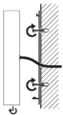
natural_image
Pure electrical circuit lines without any symbols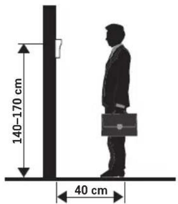
text_image
140-170 cm 40 cm2
flowchart
graph TD
    A["1×"] --> B["PROGRAM"]
    B --> C["EXIT"]
    D["1×"] --> E["3×"]
    E --> F["EXIT"]
3
GB | Colour Door Camera Unit
Package contents:
Camera unit
Mount
Attachment for adjusting the lens angle
RFID chips
Mounting material
Screwdriver
Manual
Description of the device: fig. 1a
1 - Microphone
2 - IR illumination
3 - Lens
4 - Numeric keypad
5 - IC reader - RFID chips
6 - Ring button
7 – Speaker
Description of the device: fig. 1b
1 – Video mode selection button
- Hold the button for 5 s to switch modes.
2 - Button for programming RFID key fobs
- Values are set using the turn knobs on the back of the door camera unit (covered by a rubber seal).
3 - Button for setting the duration (1-10 s) for controlling the door lock
- Values are set using the turn knobs on the back of the door camera unit (covered by a rubber seal).
4 - Volume setting for the camera unit
Terminal Description
1 - red - 12 V
2-white-audio
3 - black - GND
4 - yellow - video
Volt-Free Contacts
5 - green - NC
6 - blue - COM
7-brown-NO
12 V Lock Outlet
8 - purple - +12 V for the lock
Button
9 - orange - EXIT button
External Power Supply
10 - grey - +12 V power supply
Entering the programming MENU:
Enter the factory preset code (123456) for entering the programming MENU and press #. You will hear a double long beep.
Changing the code for entering the programming MENU:
-
Press 0 and #. You will hear a single long beep.
-
Enter a new 6-digit code and press #. You will hear a single long beep.
- Press * to exit the programming MENU. You will hear a double beep.
Setting an unlock code:
- Input the code for entering the programming MENU (either 123456 or the code you chose). You will hear a double long beep.
- Press 1 and # to enter the password setting MENU. You will hear a single long beep.
- Enter a 3-digit location (cell) code from 000 to 199 and press #. You will hear a long beep.
- Enter a 6-digit code and press # to save the code in the door unit's memory. You will hear a single long beep as confirmation. If the given location (cell) is occupied, you will hear a short double beep and have to repeat the process.
- You can gradually add codes after hearing the confirmation sound (a single long beep) by pressing #. The next code you enter will be automatically saved into the next location (cell).
- Press * twice to exit the programming MENU. You will hear a short double beep.
Erasing an unlock code:
- Input the code for entering the programming MENU (either 123456 or the code you chose). You will hear a double long beep.
- Press 2 and # to enter the code deletion mode. You will hear a single long beep.
-
Enter the 3-digit location (cell) code (from 000 to 199) of the cell you wish to delete the code for and press # to erase the code for this location (cell). You will hear a single long beep.
-
If you wish to erase all unlock codes, enter 99 instead of the 3-digit location (cell) code and press # to erase all unlock codes.
- You can also gradually erase codes after hearing the confirmation sound (a single long beep) by pressing # . Doing so will automatically select the code for the next location (cell) for deletion.
- Press * twice to exit the deletion mode. You will hear a short double beep.
Setting an RFID code:
- Input the code for entering the programming MENU (either 123456 or the code you chose). You will hear a double long beep.
- Press 3 and # to enter the password setting MENU. You will hear a single long beep.
- Enter a 3-digit location (cell) code from 000 to 199 and press #. You will hear a long beep.
- Use an RFID chip on the IC reader. You will hear a single long beep, indicating the chip was successfully saved. If the given chip is already in the door unit's memory, you will hear a short double beep.
- You can use chips on the IC reader one after another and they will automatically be saved into consecutive locations (cells).
- Press * twice to exit the programming MENU. You will hear a short double beep.
Deleting an RFID code:
- Input the code for entering the programming MENU (either 123456 or the code you chose). You will hear a double long beep.
- Press 4 and # to enter the code deletion mode. You will hear a single long beep.
- Enter the 3-digit location (cell) code (from 000 to 199) of the cell you wish to delete the code for and press # to erase the code for this location (cell). You will hear a single long beep.
- If you wish to erase all unlock codes, enter 99 instead of the 3-digit location (cell) code and press # to erase all unlock codes.
-
You can also gradually erase codes after hearing the confirmation sound (a single long beep) by pressing #. Doing so will automatically select the code for the next location (cell) for deletion.
-
Press * twice to exit the deletion mode. You will hear a short double beep.
Setting keypad illumination:
- Input the code for entering the programming MENU (either 123456 or the code you chose). You will hear a double long beep.
- Press 7 and # to enter the keypad programming MENU. You will hear a single long beep.
- Enter:
a. 00 – keypad illumination off
b. 01 - keypad illumination always on
c. 02 – keypad illumination on only when the keypad is in use, otherwise off - Press # to confirm. You will hear a single long beep.
- Press * once to exit the keypad programming MENU. You will hear a short beep.
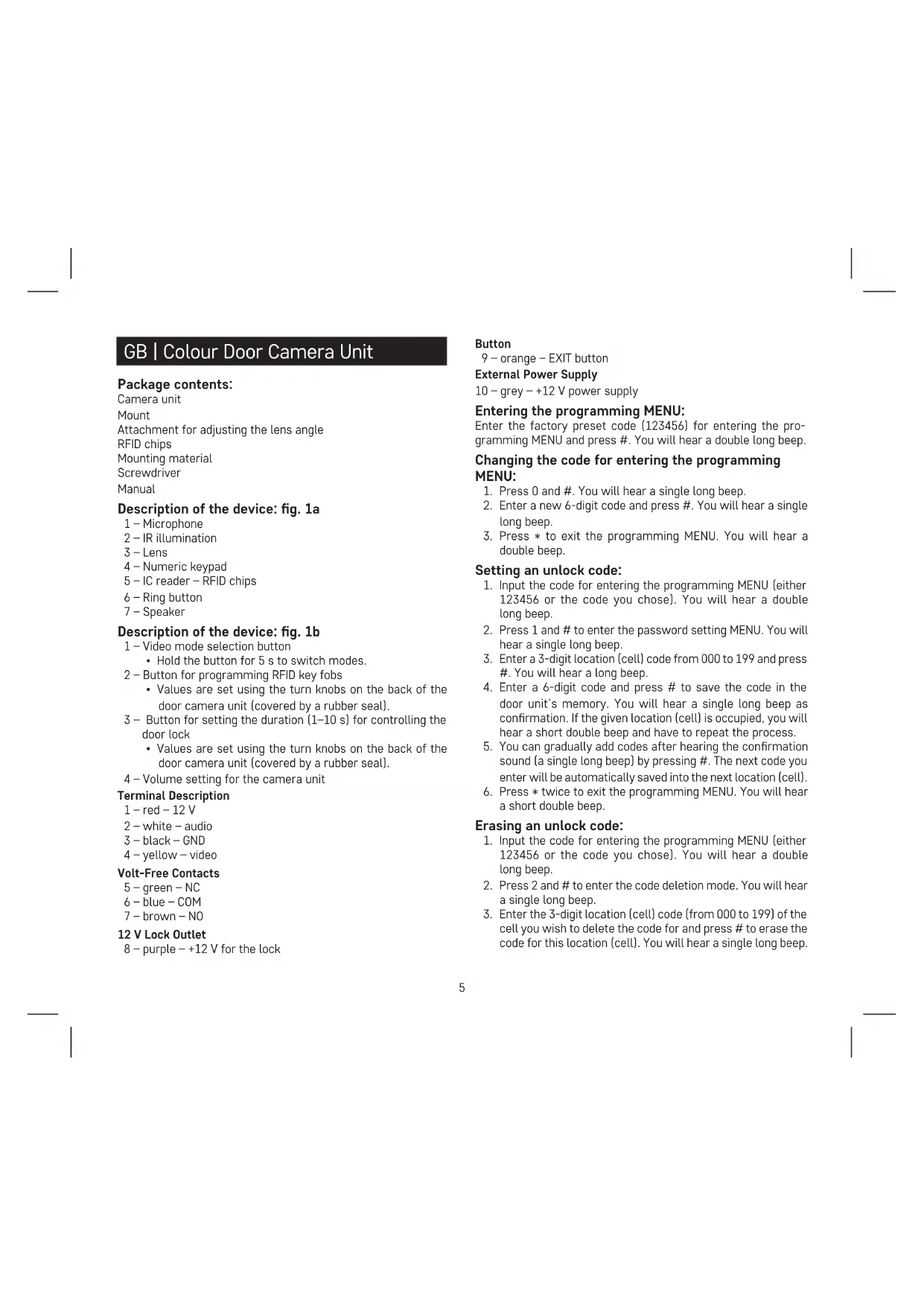
Installation
Installing the Door Camera Unit
(See Fig. 2)
Choose a suitable mounting spot and install the mounting frame. Pull the connection cable through the mounting opening and connect it to the door camera unit's wiring. Mount the connected door camera unit onto the mounting frame using the enclosed screws.
Door Camera Unit on Plaster
Apply a layer of silicone between the wall and the door camera unit to prevent ingress of humidity under the door camera unit. The silicone should be applied on the top and the sides. The bottom side must be left open to allow humid air from exiting the space under the door camera unit.
Parameters of Connection Cables
For distances under 20 m, use a high-quality shielded FTP CAT.5 cable (optimally CAT.6). For distances over 20 m, we recommend a SYKFY 5 × 2 × 0.5 or 10 × 2 × 0.5 cable. To achieve a higher cross-section, the cables can be doubled or tripled.
The resulting diameter of the conductors is as shown in the table:
| Conductor core diameter (mm) | Distance (m) |
| 0.5 20 | |
| 0.65 50 | |
| 0.8 70 | |
| 1 115 |
In basic implementation, there is no need to use a coaxial cable to transmit the video component.
Such a cable is only recommended for distances over 100 m. For long ground cabling, you can use a telecommunication cable of category TCEPKPFLE.
Basic Operation of the Device
To ring the bell and call up the image from the door camera unit on the videophone, press the button on the door camera unit.
Audio from outside will also be transmitted to the monitor.
Device Maintenance
The panel is low-maintenance. It is recommended, based on the condition of the device, to occasionally wipe the device down with a moistened cloth.
Attention! Always power down the device by disconnecting it from mains power before cleaning it!
FAQ
The image/sound is not clear, the device does not ring
Remove the monitor or the door camera unit and connect it using a short cable to eliminate the possibility of an interrupted conductor in the house. Then check the image and sound settings (brightness, contrast, colour, volume).
The lens steams up
This occurs mainly during cold weather, where condensation occurs due to the temperature difference between the wall and the door camera unit itself. If water condenses on the lens, we recommend thoroughly drying the door camera unit and adjusting the installation.
Spontaneous ringing
Spontaneous ringing is caused by moisture entering the door camera unit. Water short-circuits the contacts on the lock switch and the device will start ringing on its own.
We recommend dismounting the door camera unit, drying it thoroughly and spraying it with a water repellent for electronics.
High-pitched noise (feedback)
The source of feedback is the scattering of output sound from the door camera unit. The sound scatters and is fed back into the microphone, where it is further amplified. You can solve this by decreasing the microphone sensitivity and speaker volume. In door units with adjustable elements, you can do this by turning the potentiometers.
In units without these control elements, you can reduce the microphone volume mechanically by a piece of soft foam.
The device does not open the lock
Check that the cabling is intact. Measure the voltage on the lock terminals using a multimeter. The lock requires a voltage of 12 V to trigger. If the value is lower, use stronger conductors for the lock control.
Sudden decrease in microphone sensitivity
Check the cleanliness of the microphone opening, or clean it gently with a thin, blunt object. Be careful not to damage the microphone!

Do not dispose with domestic waste. Use special collection points for sorted waste. Contact local authorities for information about collection points. If the electronic devices
would be disposed on landfill, dangerous substances may reach groundwater and subsequently food chain, where it could affect human health.
Hereby, EMOS spol. s r.o. declares that the radio equipment type H3019 is in compliance with Directive 2014/53/EU. The full text of the EU declaration of conformity is available at the following internet address: http://www.emos.eu/download.