
AC5552 - Air-conditioner TRISTAR - Free user manual and instructions
Find the device manual for free AC5552 TRISTAR in PDF.
| Product type | Monobloc mobile air conditioner |
| Brand | TriStar |
| Model | AC5552 |
| Nominal cooling capacity | 3.517 kW |
| Nominal heating capacity | 2.784 kW |
| Power input in cooling | 1.337 kW |
| Power input in heating | 1.118 kW |
| EER (energy efficiency in cooling) | 2.63 |
| COP (coefficient of performance in heating) | 2.49 |
| Standby power consumption | 0.50 W |
| Sound power level | 65 dB(A) |
| Refrigerant | R290, 0.24 kg |
| Global warming potential (GWP) | 3 |
| Supply voltage | 220-240 V, 50-60 Hz |
| Operating modes | Cooling, Heating, Fan, Dehumidification (Dry), Night |
| Timer | 1 to 24 hours |
| Fan speeds | High, Medium, Low |
| Temperature range | 16 °C to 32 °C |
| Blade oscillation | Yes (vertical) |
| Air filter | Washable and removable |
| Minimum room area | 12 m² |
| Maintenance | Regular filter cleaning, manual drain pan emptying |
| Safety | Do not cover, do not use near water, overload protection |
Frequently Asked Questions - AC5552 TRISTAR
User questions about AC5552 TRISTAR
0 question about this device. Answer the ones you know or ask your own.
Ask a new question about this device
Download the instructions for your Air-conditioner in PDF format for free! Find your manual AC5552 - TRISTAR and take your electronic device back in hand. On this page are published all the documents necessary for the use of your device. AC5552 by TRISTAR.
USER MANUAL AC5552 TRISTAR
natural_image
White TRISTAR air purifier with black lid and control panel (no visible text or symbols on body)EN | Instruction manual
Local air conditioner
\*\*\* TRISTAR
PARTS DESCRIPTION / ONDERDELENBESCHRUVING / DESCRIPTION DES PIÈCES / TEILEBESCHREIBUNG / DESCRIPCIÓN DE LAS PIEZAS / DESCRIÇÃO DOS COMPONENTES / DESCRIZIONE DELLE PARTI / BESKRIVNING AV DELAR / OPIS CZĘŚCI / POPIS SOUČASTÍ / POPIS SÜČASTÍ / BESKRIVELSE AF BESTANDELE / OSIEN KUVAUKSET / BESKRIVELSE AV DELER

text_image
Labeled diagram of a white electronic air conditioner unit with numbered parts for identification and assembly reference.SAFETY
- Please read this user's manual carefully to ensure proper use, maintenance and installation.
- By ignoring the safety instructions the manufacturer cannot be held responsible for the damage.
• The appliance is for indoor use only. - Do not use the unit on a socket that is damaged or that has not been installed correctly.
- Do not use the unit:
- near a source of fire.
– in an area where oil is likely to splash.
– in an area exposed to direct sunlight.
– in an area where water is likely to splash. - near a bath, a shower or a swimming pool.
- Never insert your fingers or objects into the air outlet. Take special care to warn children of these dangers.
- Keep the unit upright during transport and storage.
- Before cleaning the unit, always turn off or disconnect the power supply.
• Always turn off and disconnect the power supply before moving the unit.
- WARNING: To avoid the risk of fire, do not cover the unit.
- All the unit sockets must comply with the local electric safety requirements. If necessary please check.
- If the supply cord is damaged, it must be replaced by the manufacturer, its service agent or similarly qualified persons in order to avoid a hazard.
- If the supply cord is damaged, it must be replaced by the manufacturer, service agent or qualified person(s) in order to avoid a hazard.
- This appliance can be used by children aged 8 years and above, persons with reduced physical, sensory, and mental capabilities or persons with a lack of experience and knowledge if they have been given correct supervision or instruction concerning the use of the appliance in a safe way and understand the hazards involved. Children should not play with the appliance. Cleaning and user maintenance should not be carried out by children without supervision.


STAR
Instruction manual
- This appliance is only to be used for household purposes and only for the purpose it is made for.
- Notes:
– In the case of any damage, please disconnect the power supply and contact the dealer or a designated repair shop.
– In any case, the power cord shall be firmly grounded. - To avoid the possibility of danger, if the power cord is damaged, please disconnect the power supply. It must be replaced by the dealer or a designated repair shop.
- Please use the recommended defrosting and cleaning process from the manufacturer only. Do not accelerate the defrosting or cleaning process in any other way.
- The appliance shall be stored in a room without continuously operating ignition sources (for example: open flames, an operating gas appliance or an operating electric heater).
- Do not pierce or burn.
- Be aware that refrigerants may not contain an odor.
Warning
- The appliance should be installed, operated and stored in a room with a floor area larger than 12 m2. (X=4 for 5000Btu/h, 7000Btu/h, 8000Btu/h; X=7.7 for 9000Btu/h. 10000Btu/h, 10500Btu/h)
- Only contact an authorized service technician for repair or maintenance of this unit.
- Do not pull, deform or modify the power supply cord or immerse in water. Pulling or misuse of the power supply cord could result in damage to the unit and cause an electrical shock.
- Compliance with national gas regulations should be observed.
- Keep ventilation openings clear of obstructions.
-
Any person who is involved with working on or opening a refrigerant circuit should hold a current valid certificate from an industry accredited assessment authority which authorizes their competence to handle refrigerants safely in accordance with an industry recognized assessment specification.
-
Servicing should only be performed as recommended by the equipment manufacturer. Maintenance and repair requiring the assistance of other skilled personnel should be carried out under the supervision of a person(s) competent in the use of flammable refrigerants.
- Do not stop the unit by pulling out the power plug whilst in operation as this may cause an electric shock or fire due to heat generation unless strange sounds are heard or if strange smells or smoke appear from the unit.


Specific information regarding appliances with R 290 refrigerant gas.
• Thoroughly read all of the warnings.
- When defrosting and cleaning the appliance, do not use any tools other than those recommended by the manufacturing company.
- The appliance should not be stored in a room with continuously operating ignition sources (for example: open flames, an operating gas appliance or an operating electric heater).
- Do not puncture and do not burn.
- Appliance shall be installed, operated and stored in a room with a floor area larger than 12 m2. (X=4 for 5000Btu/h, 7000Btu/h, 8000Btu/h; X=7.7 for 9000Btu/h. 10000Btu/h, 10500Btu/h)
- This appliance contains Y g (see rating label back of unit) of R290 refrigerant gas.
- R290 is a refrigerant gas that complies with the European directives on the environment. Do not puncture any part of the refrigerant circuit.
- If the appliance is installed, operated or stored in a non-ventilated area, the room must be designed to prevent to the accumulation of refrigerant leaks that could result in a fire risk or explosion due to ignition of the refrigerant caused by electric heaters, stoves, or other sources of ignition.
- The appliance must be stored in such a way as to prevent mechanical failure.

STAR
Instruction manual
- Individuals who operate or work on the refrigerant circuit must have the appropriate certification issued by an accredited organization that ensures competence in handling refrigerants according to a specific evaluation recognized by associations in the industry.
- Repairs must be performed based on the recommendation from the manufacturing company. Maintenance and repairs that require the assistance of other qualified personnel must be performed under the supervision of an individual specified in the use of flammable refrigerants.
Batteries
- Do not expose the battery to high temperatures or direct sunlight. Never throw batteries into the fire. There is a danger of explosion!
- Keep batteries away from children. Batteries are not a toy!
- Do not open the batteries by force.
-
Avoid contact with metallic objects.(Rings, nails, screws et cetera) there is a danger of short-circuiting!
-
As a result of a short-circuit batteries may heat up consider-ably or even catch fire. this may result in burns.
- For your safety the battery poles should be covered with adhesive strips during transport.
- Do not touch a ruptured and/or leaking battery. If the liquid from the battery gets into your eyes, rinse your eyes as soon as possible with clean water, without rubbing your eyes. Immediately go to the hospital. If it is not treated properly, it can cause eye problems.
Refrigerant
(CE) N 842/2006: This unit contains the refrigerant R290. The amount of refrigerant is less than 1kg , and is in a closed cooling circuit. The coolant does have zero ozone depletion potential, but is a so-called greenhouse gases under the Kyoto Protocol and may thus contribute to global warming, if it is released to the atmosphere. Therefore only trained technicians with refrigerant certificate make a filling or emptying. Your appliance does not have be refilled with refrigerant if used properly and has an undamaged coolant circuit. GWP: R290: 3
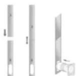
PARTS DESCRIPTION
- Control panel
- Air outlet with swinging louvers
-
Front panel
-
Air inlet with air filter
- Recessed handle
- Air exhaust
- Drain opening with sealing plug
- Remote control
- Exhaust hose
- Exhaust hose adaptor
- Slider
- Slider adaptor
BEFORE THE FIRST USE
• Take the appliance and accessories out the box. Remove the stickers, protective foil or plastic from the appliance.
- Before using your appliance for the first time, wipe off all removable parts with a damp cloth. Never use abrasive products.
- Place the device on a flat stable surface and ensure a minimum of 50 cm. free space around the device. This device is not suitable for installation in a cabinet or for outside use.
- Put the power cable into the socket. (Note: Make sure the voltage which is indicated on the device matches the local voltage before connecting the device. Voltage 220V-240V 50/60Hz)
- When the device is turned on for the first time, a slight odour will occur. This is normal, ensure adequate ventilation. This fragrance is only temporary and will disappear soon.
INSTALLATION
- The air-conditioner should be installed on a flat and stable surface. Do not block the air outlet and allow at least 50cm around the unit.
- Socket wiring should be in accordance with the local electric safety requirements.
- If the unit has been tipped at more than 45^ , allow it to stand upright for at least 24 hours before turning it on.
- Do not operate in close proximity to curtains or other objects that may block the air inlet and outlet.
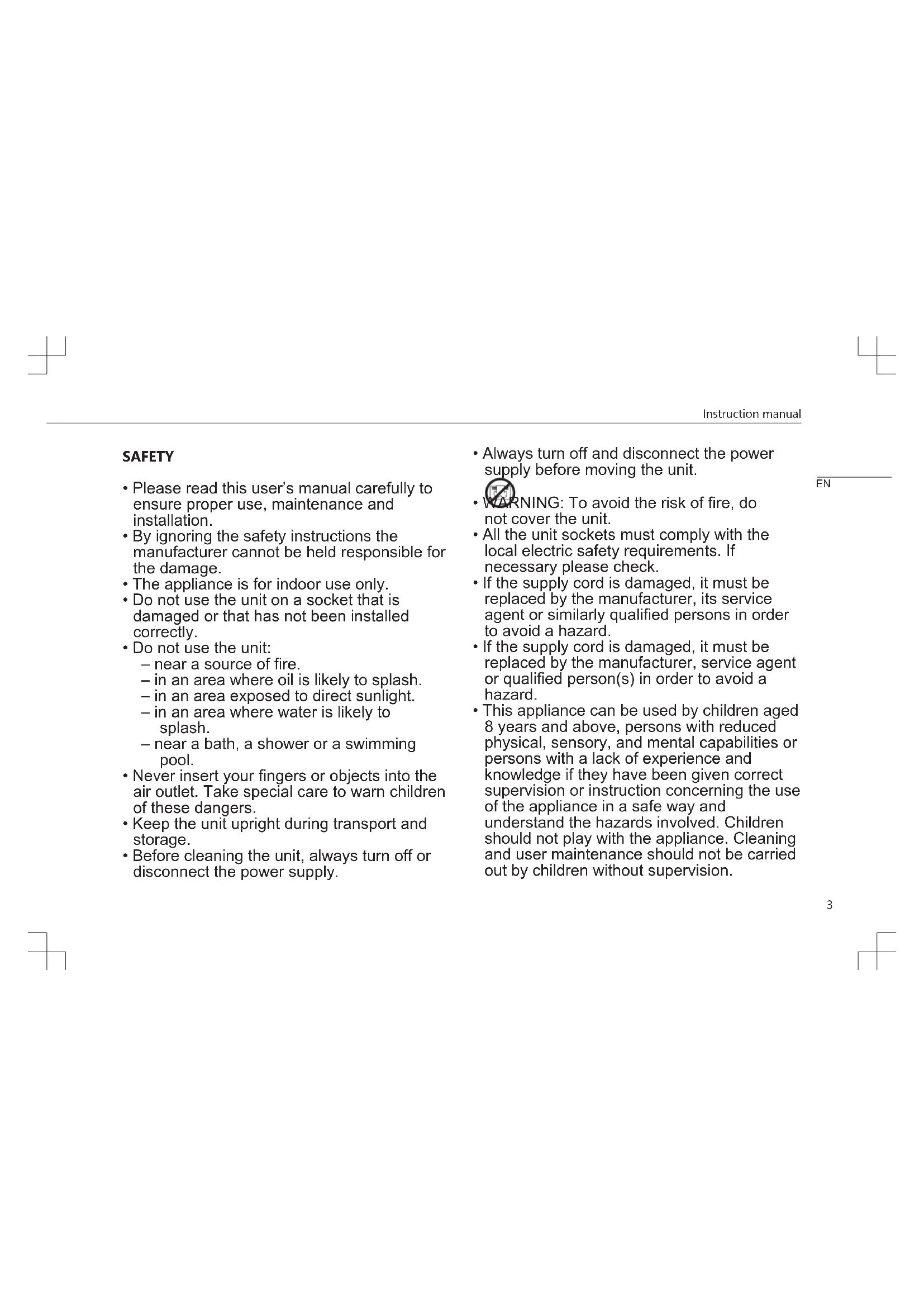
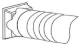
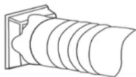
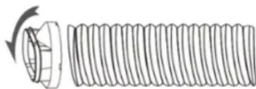
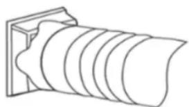
Exhaust Hose Installation
- Attach one the end of the exhaust hose to the exhaust hose adaptor.

natural_image
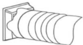
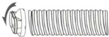
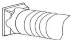
Diagram of a cylindrical object with concentric grooves, mounted on a rectangular base (no text or symbols)- Attach the slider adaptor to the other end of the exhaust hose.

natural_image
Diagram of a threaded bolt with a flanged end and rotation arrow (no text or symbols)
STAR
Instruction manual
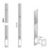
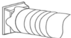
- Attach and extend the adjustable slider to meet the length of your window and connect the exhaust hose to the slider.

- Close the window to secure the slider in place. It must hold the slider firmly in place. For maximum efficiency, we recommend that any gaps between the adaptor and the slides of the window be sealed off. Use duct tape if necessary.

natural_image
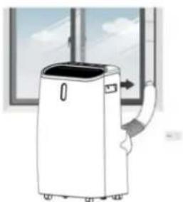
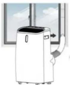
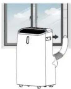
Simple line drawing of a window with a cable and arrow indicating direction (no text or symbols)- Attach the exhaust hose adaptor to the exhaust air outlet on the unit.
- Adjust the length of the flexible exhaust hose and avoid making any sharp bends in it.

natural_image
Illustration of a white portable air conditioner unit with airflow and ventilation duct, set against a window background (no text or symbols)- Plug in the unit and switch it on.
CONTROL PANEL AND DISPLAY
| 1. POWER Press to switch the unit ON or OFF | |
| 2. MODE Press to switch the operating mode between COOL, DRY, FAN and HEAT. | |
| 3. MODE INDICATOR This displays the selected mode. | |
| 4. SLEEP Press to turn sleep mode ON or OFF | |
| 5. DOWN Press to decrease the temperature or timer settings (16°C - 32°C). | |
| 6. SWING Press to adjust the vertical direction of the air flow. | |
| 7. SPEED Press to switch the fan speed to HIGH, MEDIUM or LOW. | |
| 8. LED INDICATORS Displays the selected fan speed. | |
| 9. TIMER Press to set the timer for the unit to automatically START and STOP. | |
| 10. UP Press to increase the temperature or timer settings (16°C - 32°C) | |
| 11. DIGITAL DISPLAY Displays timer and temperature settings. |
USE
Startup and shut down
- Press the POWER button to turn the unit on. The unit will run in FAN mode as default.
- Press the MODE button to select the desired operation.
- Press POWER again to turn off the power.
Operating Modes
The unit has 5 operating Modes - COOL, HEAT, FAN, DRY, and SLEEP.
COOL
- Press the MODE button repeatedly until the COOL operation LED lights up.
-
Use the UP and DOWN buttons to adjust the displayed temperature to your desired temperature. The temperature can be set between 16^ and 32^ .
-
Set the fan speed by pressing the SPEED button repeatedly until the desired speed is selected.
- Press the SWING button to spread the direction of the air horizontally.
The air conditioner will automatically stop if the room temperature is lower than the selected temperature.
HEAT
- Press the MODE button repeatedly until the HEAT operation LED lights up.
- Use the UP and DOWN buttons to adjust the displayed temperature higher than the room temperature.
- Set the fan speed by pressing the SPEED button repeatedly until the desired speed is selected.
- For continuous operating the drainage hose should be attached to the unit.
FAN
In FAN mode the air in the room is circulated and not cooled.
- Press the MODE button repeatedly until the FAN operation LED lights up.
- Set the fan speed by pressing the SPEED button repeatedly until the desired speed is selected.
DRY
- Connect the drainage hose to the drainage outlet at the bottom of the unit.
- Press the MODE button repeatedly until the DRY operation LED lights up. The fan speed switches over to low and both the fan speed and the temperature cannot be adjusted.
SLEEP

TRISTAR
Instruction manual
The SLEEP mode can be activated while using COOL or HEAT modes.
In COOL mode
- Press the SLEEP button while the unit is in COOL mode.
• After 1 hour the pre-set temperature will increase by 1^ C. After 2 hours it will increase again by 1^ C.
In HEAT mode
- Press the SLEEP button while the unit is in HEAT mode.
- After 1 hour the pre-set temperature will decrease by 1^ . After 2 hours it will decrease again by 1^ , then the temperature will be kept constant for 10 hours. During this time all the LED indicator lights will be dimmed, the fan speed will switch over to low for silent operating and the speed cannot be selected.
TIMER (1 - 24 hours)
The timer has 2 ways of operating-
To automatically turn the unit OFF.
- Press the TIMER button.
- Press the UP and DOWN buttons repeatedly to set the delay OFF time.
To automatically turn the unit ON.
- Press the TIMER button.
- Press the UP and DOWN buttons repeatedly to set the delay ON time.
To cancel the timer press the POWER button or press the DOWN button repeatedly until the display shows "00".
Automatic defrost
Frost may build up in the evaporator during operations at low temperatures. When this happens the unit will automatically start defrosting and the POWER LED will start blinking.
- If in COOL operating mode the unit will stop operating for 10 minutes and automatically restart in COOL operating mode.
- If in HEAT or DRY operating mode the unit will shut down for 20 minutes then spend 5 minutes defrosting.
Overload protection
In the event of a power loss, the compressor will require 3 minutes before restarting.
Drainage
Manual drainage
- The unit will shut down when the water needs to be drained, when this happens unplug the unit from the power supply.
- Move the unit to a suitable place for emptying the water pan at the bottom of the unit.
- Unplug the water plug. Let the water run out into a container. The unit may be tilted slightly backward to help the water escape.
- Once emptied, plug back the water plug and ensure that it is well fitted.
- Plug in and restart the unit.

natural_image
Line drawing of a dual air conditioner unit with fan and vent (no text or symbols)Continuous drainage
During DRY operating mode and in high humidity conditions and for continuous operation.
- Switch off and unplug the unit from the power supply.
- Remove the plug from the water outlet opening.
- Securely attach the drain hose to the water outlet opening.
- Place the outlet hose over a bucket and allow it to drain.
- Do not submerge the drain hose in water as this may cause "air lock" in the hose.
TABLE AC-5552
| Information requirements for single and double duct air conditioners | P | ||
| Information to identify the model(s) to which the information relates to: | |||
| Description Symbol Value Unit | |||
| Rated capacity for cooling | Prated for cooling | 3.517 KW | |
| Rated capacity for heating | Prated for heating | 2.784 KW | |
| Rated power input for cooling | Peer 1.337 KW | ||
| Rated power input for heating | Pcop 1.118 KW | ||
| Rated Energy efficiency ratio | EERd 2.63 - | ||
| Rated Coefficient of performance | COPd 2.49 - | ||
| Information to identify the model(s) to which the information relates to: | |||
| Description Symbol Value Unit | |||
| Power consumption in thermostat-off mode | Pto - W | ||
| Power consumption in standby mode | Psb 0.50 W | ||
EN

TRISTAR
Instruction manual
| Electricity consumption of single/double duct appliances (indicate for cooling and heating separately) | Qsd SD: 1.335 for coolingSD: 1.116 for heating | kWh/h |
| Sound power level Lwa 65 dB(A) | ||
| Global warming potential | GWP 3 kgCO2eq. |
CLEANING MAINTENANCE
- Before cleaning, disconnect the unit from any electric supply outlet.
- First clean the surface with a neutral detergent and wet cloth, and then wipe it with a dry cloth.
- Do not use gasoline or other chemicals to clean the unit.
- Do not wash the unit directly.
Cleaning the air filters
The air filters requires regular cleaning. The filters are removable for easy cleaning. Do not operate the unit without the air filter.
- Turn off and unplug the unit.
- Remove the 2 filters from the unit.
- Use a vacuum cleaner to gently remove dust from the filter.
- Wash the filter under running water.
- Let the filter completely dry before reattaching it.
- Do not touch the inside of the unit when the filters are removed.

natural_image
Illustration of a faucet spraying water onto a grid-patterned surface (no text or symbols)TROUBLESHOOTING
| Symptom Inspection Solution | ||
| The unit is not operating | Check that power connection is secure.Check the room temperature.Check the water. | Insert the power cord securely in the socket.The range for operating is between 5^ - 35^ .Remove the rubber plug and drain the unit. |
| The unit works with reduced capacity | Check the air filter for dirt.Check if the air duct is blocked.Check if the doors or windows are open.Check if the desired operation is selected and the temperature is properly set.The exhaust hose is detached | Clean the air filter if necessary.Clear the obstacle.Keep doors and windows closed.Select the desired operation.Make sure that the exhaust hose is properly attached. |
| Water leakage | Overflow while moving the unit.Check if the drain hose is kinked or bent. | Empty the water before transporting.Straighten the hose. |
| Excessive noise | Check if the unit is securely positioned. Noise sounds like water flowing. Check for loose vibrating external parts. | Place the unit on a flat, level, horizontal surface. Noise comes from flowing refrigerant. This is normal. Secure and tighten loose external parts. |
| Error Codes | ||
| E0 Comm | unication fault between main PCB and display PCB | Check the wire harness of the PCB for damage. |
| E1 Ambient temperature sensor failure. | Check connection. Clean or replace the temperature sensor. |
| E2 Coil temperature sensor failure. | Check connection. Clean or replace the temperature sensor. |
| Ft Condensate water high level alarm. | Remove the rubber plug and drain the unit, |
THE PRODUCT OR EQUIPMENT CONTAINS FLUORINATED GREENHOUSE GAS.
| Art.nr. AC-5552 | |
| Coolant: R290 | |
| Quantity in kg: 0.24 | |
| Global Warming Potential: 3 | |
| CO2 Equivalent in tons: 0.00072 |
ENVIRONMENT

This appliance should not be put into the domestic garbage at the end of its durability, but must be offered at a central point for the recycling of electric and electronic domestic appliances. This symbol on the appliance, instruction manual and packaging puts your attention to this important issue. The materials used in this appliance

TRISTAR
Instruction manual
can be recycled. By recycling of used domestic appliances you contribute an important push to the protection of our environment. Ask your local authorities for information regarding the point of recollection.
The European directive for batteries (2006/66/EC) states that it is not permitted to throw batteries away with the household waste. They may contain substances which are harmful to the environment. Empty batteries can be handed over to a local, public collection point or a local recycling centre. To avoid overheating as a result of a short circuit, lithium batteries must be removed from the product and the poles must be protected using insulation tape or some other means against short-circuiting.
You can find all available information and spare parts at www.tristar.eu!
VEILIGHEID
Exhaust Hose Installation
- Attach one the end of the exhaust hose to the exhaust hose adaptor.
natural_image
Line drawing of a cylindrical object with concentric grooves, mounted on a rectangular base (no text or symbols)- Attach the slider adaptor to the other end of the exhaust hose.

natural_image
Diagram of a coiled spring with a rotating head and spiral blades (no text or symbols)- Attach and extend the adjustable slider to meet the length of your window and connect the exhaust hose to the slider.
- Close the window to secure the slider in place. It must hold the slider firmly in place. For maximum efficiency, we recommend that any gaps between the adaptor and the slides of the window be sealed off. Use duct tape if necessary.

natural_image
Diagram showing a window with a pipe extending into the corner and an arrow indicating direction (no text or symbols)- Attach the exhaust hose adaptor to the exhaust air outlet on the unit.
- Adjust the length of the flexible exhaust hose and avoid making any sharp bends in it.

natural_image
Illustration of a portable air conditioner unit with airflow direction indicated (no text or symbols)- Plug in the unit and switch it on.
BEDIENINGSPANEELE EN DISPLAY
The unit has 5 operating Modes - COOL, HEAT, FAN, DRY and SLEEP.
COOL
- Press the MODE button repeatedly until the COOL operation LED lights up.
- Gebruik de knoppen OMHOOG en OMLAAG om de weergegeven temperatuur aan te passen. U kunt de temperatuur tussen 16 °C en 32 °C instellen.
- Set the fan speed by pressing the SPEED button repeatedly until the desired speed is selected.
- Press the SWING button to spread the direction of the air horizontally.
In FAN mode the air in the room is circulated and not cooled.
- Press the MODE button repeatedly until the FAN operation LED lights up.
- Set the fan speed by pressing the SPEED button repeatedly until the desired speed is selected.
DRY
The SLEEP mode can be activated while using COOL or HEAT modes.
In COOL mode
- If in COOL operating mode the unit will stop operating for 10 minutes and automatically restart in COOL operating mode.
- If in HEAT or DRY operating mode the unit will shut down for 20 minutes then spend 5 minutes defrosting.
natural_image
Line drawing of a dual air conditioner unit with ventilation grilles and fan (no text or symbols)natural_image
Illustration of a hand spraying water onto a grid-patterned surface (no text or symbols)PROBLEMEN OPLOSSEN
| Symptoom Controle Oplossing |
Exhaust Hose Installation
- Attach one the end of the exhaust hose to the exhaust hose adaptor.

natural_image
Line drawing of a cylindrical object with concentric grooves, mounted on a rectangular base (no text or symbols)- Attach the slider adaptor to the other end of the exhaust hose.

natural_image
Diagram of a threaded bolt with a flanged end and rotation arrow (no text or symbols)- Attach and extend the adjustable slider to meet the length of your window and connect the exhaust hose to the slider.

- Close the window to secure the slider in place. It must hold the slider firmly in place. For maximum efficiency, we recommend that any gaps between the adaptor and the slides of the window be sealed off. Use duct tape if necessary.

natural_image
Illustration of a window with a curved pipe extending into the corner, showing airflow direction (no text or symbols)- Attach the exhaust hose adaptor to the exhaust air outlet on the unit.
- Adjust the length of the flexible exhaust hose and avoid making any sharp bends in it.

natural_image
Illustration of a white portable air conditioner unit with a curved handle, placed near a window (no text or symbols visible)- Plug in the unit and switch it on.

STAR
natural_image
Line drawing of a dual air conditioner unit with ventilation grilles and fan (no text or symbols)Vidange continue
natural_image
Illustration of a faucet spraying water onto a grid-patterned surface (no text or symbols)RÉSOLUTION DES PANNES
Symptôme Inspection Solution
Exhaust Hose Installation
- Attach one the end of the exhaust hose to the exhaust hose adaptor.

natural_image
Line drawing of a cylindrical object with concentric grooves, mounted on a rectangular base (no text or symbols)- Attach the slider adaptor to the other end of the exhaust hose.

natural_image
Diagram of a threaded bolt with a flanged end and rotation arrow (no text or labels)- Attach and extend the adjustable slider to meet the length of your window and connect the exhaust hose to the slider.

- Close the window to secure the slider in place. It must hold the slider firmly in place. For maximum efficiency, we recommend that any gaps between the adaptor and the slides of the window be sealed off. Use duct tape if necessary.

natural_image
Diagram showing a window with a pipe extending into the corner and an arrow indicating direction (no text or symbols)- Attach the exhaust hose adaptor to the exhaust air outlet on the unit.
- Adjust the length of the flexible exhaust hose and avoid making any sharp bends in it.
natural_image
Illustration of a white portable air conditioner unit with a handle, placed near a window (no text or symbols visible)- Plug in the unit and switch it on.
BEDIENFELD UND DISPLAY
natural_image
Line drawing of a dual air conditioner unit with fan and ventilation grilles (no text or symbols)
TRISTAR
Bedienungsanleitung
natural_image
Illustration of a faucet spraying water onto a grid-patterned surface (no text or symbols)STÖRUNGSBESEITIGUNG
Exhaust Hose Installation
- Attach one the end of the exhaust hose to the exhaust hose adaptor.

natural_image
Line drawing of a cylindrical object with concentric grooves, mounted on a rectangular base (no text or symbols)- Attach the slider adaptor to the other end of the exhaust hose.

natural_image
Diagram of a coiled spring with a rotating shaft (no text or symbols)- Attach and extend the adjustable slider to meet the length of your window and connect the exhaust hose to the slider.

- Close the window to secure the slider in place. It must hold the slider firmly in place. For maximum efficiency, we recommend that any gaps between the adaptor and the slides of the window be sealed off. Use duct tape if necessary.

natural_image
Diagram showing a window with a curved pipe extending into the corner, indicating airflow or ventilation direction (no text or symbols)- Attach the exhaust hose adaptor to the exhaust air outlet on the unit.
- Adjust the length of the flexible exhaust hose and avoid making any sharp bends in it.

natural_image
Illustration of a white portable air conditioner unit with a curved handle, placed near a window (no text or symbols visible)- Plug in the unit and switch it on.

TRISTAR
natural_image
Line drawing of a dual air conditioner unit with ventilation grilles and fan (no text or symbols)Drenaje continuo
natural_image
Illustration of a faucet spraying water onto a grid-patterned surface (no text or symbols)Exhaust Hose Installation
- Attach one the end of the exhaust hose to the exhaust hose adaptor.
natural_image
Line drawing of a cylindrical object with concentric grooves, mounted on a rectangular base (no text or symbols)- Attach the slider adaptor to the other end of the exhaust hose.

natural_image
Diagram of a coiled spring with a rotating shaft (no text or symbols)- Attach and extend the adjustable slider to meet the length of your window and connect the exhaust hose to the slider.

- Close the window to secure the slider in place. It must hold the slider firmly in place. For maximum efficiency, we recommend that any gaps between the adaptor and the slides of the window be sealed off. Use duct tape if necessary.

natural_image
Diagram showing a window with a curved pipe extending into the corner, indicating airflow or ventilation direction (no text or symbols)- Attach the exhaust hose adaptor to the exhaust air outlet on the unit.
- Adjust the length of the flexible exhaust hose and avoid making any sharp bends in it.
natural_image
Illustration of a portable air conditioner unit with airflow direction indicated (no text or symbols)- Plug in the unit and switch it on.
PAINEL DE CONTROLO E VISOR
natural_image
Line drawing of a dual air conditioner unit with fan and cooling fans (no text or symbols)Drenagem contínua
natural_image
Illustration of a hand spraying water onto a grid-patterned surface (no text or symbols)Exhaust Hose Installation
- Attach one the end of the exhaust hose to the exhaust hose adaptor.

natural_image
Line drawing of a cylindrical object with concentric rings, mounted on a rectangular base (no text or symbols)- Attach the slider adaptor to the other end of the exhaust hose.
natural_image
Diagram of a threaded bolt with a flanged end and rotation arrow (no text or symbols)- Attach and extend the adjustable slider to meet the length of your window and connect the exhaust hose to the slider.

- Close the window to secure the slider in place. It must hold the slider firmly in place. For maximum efficiency, we recommend that any gaps between the adaptor and the slides of the window be sealed off. Use duct tape if necessary.

natural_image
Simple line drawing of a window with a curved pipe extending from the side, showing airflow or fluid flow direction (no text or symbols)- Attach the exhaust hose adaptor to the exhaust air outlet on the unit.
- Adjust the length of the flexible exhaust hose and avoid making any sharp bends in it.

STAR
natural_image
Illustration of a portable air conditioner unit with airflow direction indicated by arrows (no text or symbols)- Plug in the unit and switch it on.
PANNELLO COMANDI E DISPLAY
natural_image
Line drawing of a dual air conditioner unit with ventilation grilles and fan (no text or symbols)Drenaggio continuo
natural_image
Illustration of a faucet spraying water onto a grid-patterned surface (no text or symbols)Exhaust Hose Installation
- Attach one the end of the exhaust hose to the exhaust hose adaptor.

natural_image
Line drawing of a cylindrical object with concentric rings, mounted on a rectangular base (no text or symbols)- Attach the slider adaptor to the other end of the exhaust hose.

natural_image
Diagram of a coiled spring with a rotating shaft (no text or symbols)- Attach and extend the adjustable slider to meet the length of your window and connect the exhaust hose to the slider.

- Close the window to secure the slider in place. It must hold the slider firmly in place. For maximum efficiency, we recommend that any gaps between the adaptor and the slides of the window be sealed off. Use duct tape if necessary.

natural_image
Illustration of a window with a curved pipe extending from the side, showing airflow or ventilation (no text or symbols)- Attach the exhaust hose adaptor to the exhaust air outlet on the unit.
- Adjust the length of the flexible exhaust hose and avoid making any sharp bends in it.

natural_image
Illustration of a white portable air conditioner unit with a curved scroll inside, placed near a window (no text or symbols visible)- Plug in the unit and switch it on.
KONTROLLPANEL OCH DISPLAY
natural_image
Line drawing of a dual air conditioner unit with ventilation grilles and fan (no text or symbols)Kontinuerlig tömning
natural_image
Illustration of a faucet spraying water onto a grid-patterned surface (no text or symbols)FELSÖKNING
Exhaust Hose Installation
- Attach one the end of the exhaust hose to the exhaust hose adaptor.

natural_image
Line drawing of a cylindrical object with concentric grooves, mounted on a rectangular base (no text or symbols)- Attach the slider adaptor to the other end of the exhaust hose.

natural_image
Diagram of a threaded bolt with a flanged head and spiral grooves (no text or symbols)- Attach and extend the adjustable slider to meet the length of your window and connect the exhaust hose to the slider.

- Close the window to secure the slider in place. It must hold the slider firmly in place. For maximum efficiency, we recommend that any gaps between the adaptor and the slides of the window be sealed off. Use duct tape if necessary.

natural_image
Illustration of a window with a hose and directional arrow, no text or symbols present- Attach the exhaust hose adaptor to the exhaust air outlet on the unit.
- Adjust the length of the flexible exhaust hose and avoid making any sharp bends in it.

natural_image
Illustration of a white portable air conditioner unit with a curved handle, placed near a window (no text or symbols visible)- Plug in the unit and switch it on.
PANEL STEROWANIA I WYŚWIETLACZ
natural_image
Line drawing of a dual air conditioner unit with ventilation grilles and fan (no text or symbols)natural_image
Illustration of a faucet spraying water onto a grid-patterned surface (no text or symbols)ROZWIĄZYWANIE PROBLEMÓW
Exhaust Hose Installation
- Attach one the end of the exhaust hose to the exhaust hose adaptor.
natural_image
Line drawing of a cylindrical object with concentric grooves, mounted on a rectangular base (no text or symbols)- Attach the slider adaptor to the other end of the exhaust hose.
natural_image
Diagram of a coiled spring with a rotating head and spiral guide (no text or symbols)- Attach and extend the adjustable slider to meet the length of your window and connect the exhaust hose to the slider.

- Close the window to secure the slider in place. It must hold the slider firmly in place. For maximum efficiency, we recommend that any gaps between the adaptor and the slides of the window be sealed off. Use duct tape if necessary.

natural_image
Diagram showing a window with a curved pipe extending into the corner, indicating airflow or ventilation direction (no text or symbols)- Attach the exhaust hose adaptor to the exhaust air outlet on the unit.
- Adjust the length of the flexible exhaust hose and avoid making any sharp bends in it.
natural_image
Illustration of a portable air conditioner unit with a handle, placed near a window (no text or symbols visible)- Plug in the unit and switch it on.
OVLÁDACÍ PANEL A DISPLEJ
natural_image
Line drawing of a dual-free air conditioner unit with ventilation grilles and fan (no text or symbols)Trvalé vypouštění
natural_image
Illustration of a faucet spraying water onto a grid-patterned surface (no text or symbols)ŘEŠENÍ PROBLÉMŮ
Exhaust Hose Installation
- Attach one the end of the exhaust hose to the exhaust hose adaptor.
natural_image
Line drawing of a cylindrical object with concentric grooves, mounted on a rectangular base (no text or symbols)- Attach the slider adaptor to the other end of the exhaust hose.

natural_image
Diagram of a solenoid with a rotating knob and spiral grooves (no text or symbols)- Attach and extend the adjustable slider to meet the length of your window and connect the exhaust hose to the slider.

- Close the window to secure the slider in place. It must hold the slider firmly in place. For maximum efficiency, we recommend that any gaps between the adaptor and the slides of the window be sealed off. Use duct tape if necessary.

natural_image
Diagram showing a window with a curved pipe extending into the corner, indicating airflow or fluid flow direction (no text or symbols)- Attach the exhaust hose adaptor to the exhaust air outlet on the unit.
- Adjust the length of the flexible exhaust hose and avoid making any sharp bends in it.

natural_image
Illustration of a portable air conditioner unit with a curved handle, placed near a window (no text or symbols visible)- Plug in the unit and switch it on.

TRISTAR
natural_image
Line drawing of a dual air conditioner unit with ventilation grilles and fan (no text or symbols)natural_image
Illustration of a faucet spraying water onto a grid-patterned surface (no text or symbols)RIEŠENIE PROBLÉMOV
Exhaust Hose Installation
- Attach one the end of the exhaust hose to the exhaust hose adaptor.
natural_image
Line drawing of a cylindrical object with concentric rings, mounted on a rectangular base (no text or symbols)- Attach the slider adaptor to the other end of the exhaust hose.

natural_image
Diagram of a threaded bolt with a flanged end and rotation arrow (no text or labels)- Attach and extend the adjustable slider to meet the length of your window and connect the exhaust hose to the slider.
- Close the window to secure the slider in place. It must hold the slider firmly in place. For maximum efficiency, we recommend that any gaps between the adaptor and the slides of the window be sealed off. Use duct tape if necessary.

natural_image
Diagram showing a window with a curved pipe extending into the corner, indicating airflow or ventilation direction (no text or symbols present)- Attach the exhaust hose adaptor to the exhaust air outlet on the unit.
- Adjust the length of the flexible exhaust hose and avoid making any sharp bends in it.

natural_image
Illustration of a portable air conditioner unit with a handle and vent, placed near a window (no text or symbols visible)- Plug in the unit and switch it on.
BETJENINGSPANEL OG DISPLAY
natural_image
Line drawing of a dual air conditioner unit with ventilation grilles and fan (no text or symbols)Kontinuerligt dræn:
natural_image
Illustration of a faucet spraying water onto a grid-patterned surface (no text or symbols)FEJLS∅GNING
Exhaust Hose Installation
- Attach one the end of the exhaust hose to the exhaust hose adaptor.
natural_image
Line drawing of a cylindrical object with concentric grooves, mounted on a rectangular base (no text or symbols)- Attach the slider adaptor to the other end of the exhaust hose.

natural_image
Diagram of a threaded bolt with a flanged end and rotation arrow (no text or labels)- Attach and extend the adjustable slider to meet the length of your window and connect the exhaust hose to the slider.

- Close the window to secure the slider in place. It must hold the slider firmly in place. For maximum efficiency, we recommend that any gaps between the adaptor and the slides of the window be sealed off. Use duct tape if necessary.
natural_image
Illustration of a window with a curved pipe extending from the side, showing airflow or ventilation (no text or symbols)- Attach the exhaust hose adaptor to the exhaust air outlet on the unit.
- Adjust the length of the flexible exhaust hose and avoid making any sharp bends in it.

natural_image
Illustration of a portable air conditioner unit with airflow direction indicated (no text or symbols)- Plug in the unit and switch it on.
SÄÄTÖPANEELI JA NÄYTTÖ
natural_image
Line drawing of a dual air conditioner unit with ventilation grilles and fan (no text or symbols)Jatkuva tyhjennys
natural_image
Illustration of a faucet spraying water onto a grid-patterned surface (no text or symbols)VIANETSINTÄ
Exhaust Hose Installation
- Attach one the end of the exhaust hose to the exhaust hose adaptor.

natural_image
Line drawing of a cylindrical object with concentric grooves, mounted on a rectangular base (no text or symbols)- Attach the slider adaptor to the other end of the exhaust hose.

natural_image
Diagram of a threaded bolt with a flanged end and rotation arrow (no text or symbols)- Attach and extend the adjustable slider to meet the length of your window and connect the exhaust hose to the slider.

- Close the window to secure the slider in place. It must hold the slider firmly in place. For maximum efficiency, we recommend that any gaps between the adaptor and the slides of the window be sealed off. Use duct tape if necessary.
\*\*\* TRISTAR Bruksanvisning

natural_image
Illustration of a window with a curved pipe extending from the side, showing airflow or ventilation direction (no text or symbols)- Attach the exhaust hose adaptor to the exhaust air outlet on the unit.
- Adjust the length of the flexible exhaust hose and avoid making any sharp bends in it.

natural_image
Illustration of a white portable air conditioner unit with airflow direction indicated by arrows, set against a window background (no text or symbols)- Plug in the unit and switch it on.
KONTROLLPANEL OG DISPLAY
natural_image
Line drawing of a dual air conditioner unit with ventilation grilles and fan (no text or symbols)Kontinuerlig drenering
natural_image
Illustration of a faucet spraying water onto a grid-patterned surface (no text or symbols)FEILS∅KING
5015 BH Tilburg | The Netherlands