
Pandora X - Basket ELICA - Free user manual and instructions
Find the device manual for free Pandora X ELICA in PDF.
| Brand | Elica |
| Model | Pandora X |
| Product Type | Cooker hood |
| Usage | Domestic |
| Use Version | Extracting (external evacuation) or filtering (internal recirculation) |
| Required Opening Dimensions | 822 mm x 100 mm (W x H) |
| Exhaust Duct Diameter | 150 mm |
| Maximum Duct Length | 5 m |
| Number of Speeds | 3 speeds + intensive |
| Automatic Shut-off Timer | Yes: 20 min (speed 1), 15 min (speed 2), 10 min (speed 3), 5 min (intensive) |
| Filter Saturation Indicator | Yes: grease filter (40h), charcoal filter (160h) |
| Grease Filter | Washable metal (dishwasher or hand wash), monthly cleaning |
| Activated Charcoal Filter | Replace every 4 months (recirculation version) |
| Minimum Distance to Cooking Surface | 65 cm (for gas cooking) |
| Power Supply | 230 V ~ 50 Hz (according to rating plate) |
| Control Type | Electronic with touch controls |
| Panel Material | Safety glass |
| Safety Standards | IEC/EN 60335-1 and 60335-2-31 |
| Protection Rating | Class I (mandatory grounding) |
Frequently Asked Questions - Pandora X ELICA
User questions about Pandora X ELICA
0 question about this device. Answer the ones you know or ask your own.
Ask a new question about this device
Download the instructions for your Basket in PDF format for free! Find your manual Pandora X - ELICA and take your electronic device back in hand. On this page are published all the documents necessary for the use of your device. Pandora X by ELICA.
USER MANUAL Pandora X ELICA
EN Installation, use and maintenance instructions
natural_image
Diagram of a kitchen appliance with a labeled component and a downward arrow indicating assembly (no text or symbols present)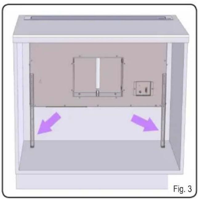
natural_image
3D diagram of a cabinet interior with two purple arrows indicating directional flow, no text or symbols present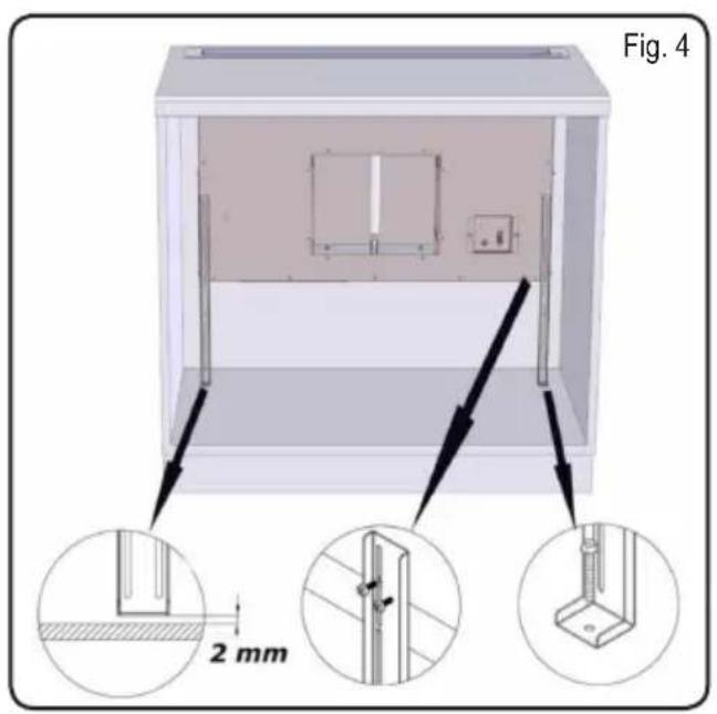
natural_image
Technical line drawing of a mechanical component with directional arrows indicating motion or force (no text or symbols)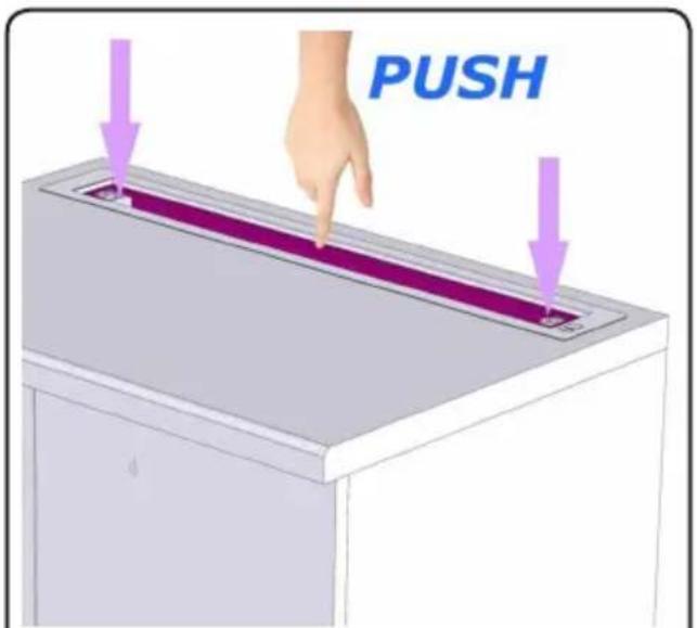
Fig. 7
natural_image
3D diagram of two rectangular panels mounted on a purple base with directional arrows indicating movement or force (no text or symbols)Fig. 8
natural_image
3D diagram of a mechanical component with a magenta block and gray base, showing a blade and rotation arrows (no text or symbols)Fig. 9
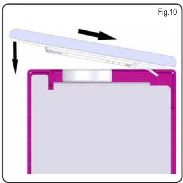
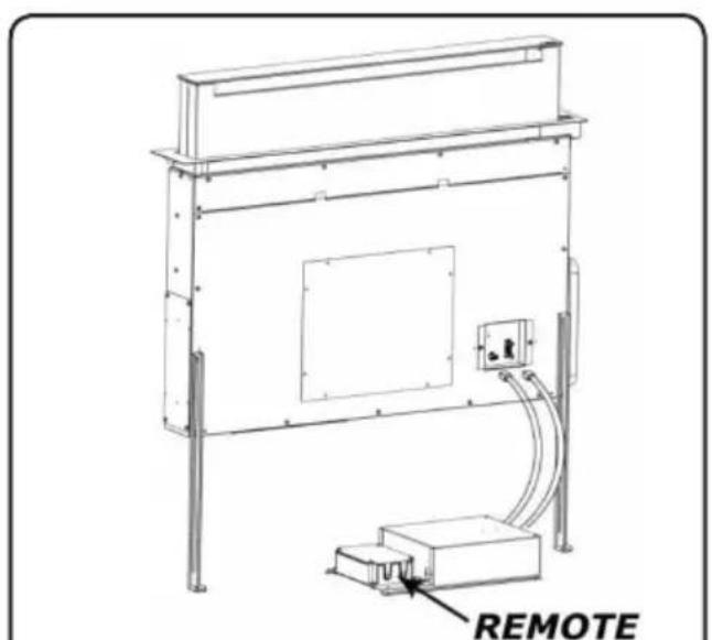
Fig. 11
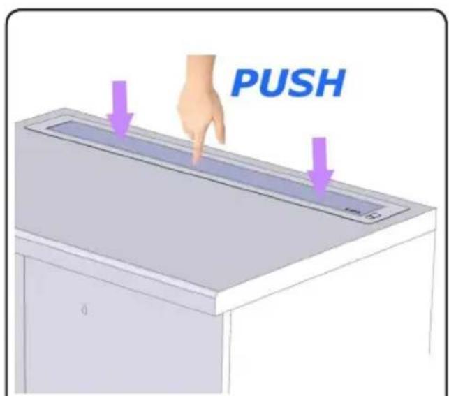
Fig. 12
Strictly follow all the instructions given in this manual.
The manufacturer declines all responsibility for any inconvenience, damages or fire caused by the appliance due to failure to comply with the instructions mentioned in this manual. The hood was designed to suction cooking fumes and vapours, therefore it is intended for household use only. The aesthetic features of the hood might be different from the ones shown in the drawings of this manual; in any case, the use, installation and maintenance instructions are the same.
! Please keep this manual for future reference. Should the appliance be sold or passed on to others, make sure that these instructions are passed on with it.
! Carefully read these instructions, where important information on the appliance installation, use and safety is provided.
! Do not perform any electrical or mechanical modifications on the appliance or on the exhaust ducts.
! Before carrying out installation, make sure that all components are not damaged. Please contact your retailer in case they are damaged, and do not proceed with the installation
WARNINGS
Before carrying out any maintenance or cleaning operations, disconnect the hood from the power supply, by unplugging it from the mains supply or by switching off the main switch.
Wear protective gloves during any installation and maintenance operation.
The appliance is not intended for use by children under 8, and by persons with reduced physical, sensory or mental capabilities, or lack of experience and knowledge, unless they have been given supervision or instructions concerning the safe use of the appliance and the risk connected to it, by a person responsible for their safety.
Children should be supervised to ensure that they do not play with the appliance.
Cleaning and maintenance operations shall not be performed by children without supervision. Adequately ventilate the room when the cooker hood and other appliances, powered by energy other than electricity, such as gas combustion or other fuels, are used simultaneously.
The hood shall be cleaned regularly, both internally and externally (AT LEAST ONCE A MONTH); please follow the instructions given in the maintenance section of this manual.
Failure to comply with the instructions provided for the hood cleaning operations, as well as filter cleaning and replacement operations, may result in fire risk.
Open flames can damage the grease filters and can cause fire risk, therefore cooking over open flames should be strictly avoided.
Deep frying should be done under constant supervision, in order to keep overheated oil from igniting.
CAUTION: When the hob is in use, the accessible parts of the hood may become hot.
Caution! Do not connect the appliance to the power source until installation is completed.
As far as the technical and safety measures, to be implemented to discharge fumes, are concerned, strictly comply with provisions set forth in relevant regulations by the local competent authorities.
Air extracted shall not be conveyed into a duct used to discharge fumes coming from appliances fed by gas combustion or other fuels.
Never use the hood without having the grid properly installed!
NEVER use the hood as a support surface unless it is expressly mentioned in the instructions. Only use the fixing screws supplied with the appliance during installation.
In case they are not supplied, please buy a suitable screw type. Use proper length screws, specific details are given in the Installation Guide. In case of doubts, please contact our authorized technical assistance center or similarly qualified personnel.
CAUTION! Fixing screws and fixing devices shall be installed according to the instructions given in this manual; failure to comply with them might result in electric risk.
The manufacturer declines all responsibility for any inconvenience, damage or fire caused by the appliance, due to failure to comply with these instructions.
Constantly seeking to improve our products, we reserve the right to modify their technical, functional, or aesthetic characteristics as a result of their upgrading.
In the case of external motor version, for the hood normal operation, it is necessary to use a suctioning unit (external motor) made by the same manufacturer.
This appliance is marked according to the European directive 2012/19/EC on Waste Electrical and Electronic Equipment (WEEE). By ensuring this product is disposed of correctly, you will help prevent potential negative consequences for the environment and human health.
The symbol 📄 on the product or on the documentation included with it, means that this product shall not be disposed of as household waste. Instead, it shall be handed over to the suitable collection point for the recycling of electrical and electronic equipment. The product shall be disposed of according to applicable local standards and regulations on waste disposal. For more detailed information on the disposal and recycling of this product, please contact your local city office, your household waste disposal service or the shop where you purchased the product.
This appliance has been designed, tested and produced in compliance with all relevant standards on:
- Safety: CEI/EN 60335-1; CEI/EN 60335-2-31, CEI/EN 62233.
• Performance: CEI/EN 61591; ISO 5167-1; ISO 5167-3; ISO 5168; CEI/EN 60704-1; CEI/EN 60704-2-13; ISO 3741; EN 50564; CEI 62301. - EMC: EN 55014-1; CISPR 14-1; EN 55014-2; CISPR 14-2; CEI/EN 61000-3-2; CEI/EN 61000-3-3.
Tips for the proper use of the appliance, aimed at reducing environmental impact.
Switch the hood on at minimum speed when you start cooking and leave it in operation for some minutes after you finish cooking. Increase the speed only in case of high quantities of fumes and vapours, using the boost feature only when absolutely necessary.
In order to keep the odour reducing system efficient over time, replace the charcoal filter/s whenever necessary.
In order to keep the grease filter efficient over time, clean it whenever necessary.
Use a piping system with the maximum diameter specified in this manual, in order to reach very high performances and maintain low noise levels.
Use
The hood can be used both in aspiration mode with external discharge of suctioned air, and in filtering mode, where the air is recycled back into the room.
Aspiration Mode

Vapours are discharged to the outside, through the specific exhaust pipe fixed to the flange.
The exhaust pipe diameter shall be the same as the connection ring diameter.
Caution! The exhaust pipe is not supplied with the appliance and shall be purchased. The pipe shall have a light upwards inclination (about 10^ ) in its horizontal part, in order to convey the air to the outside more easily. If the hood is equipped with charcoal filters, they shall be removed.
Filtering mode

The air that is sucked in will be ‘degreased’ before being re-conveyed into the room. If you wish to use the hood in this mode, you will need to buy an additional filtering system with activated charcoal filers.
Note: The air recycled through the charcoal filters is conveyed back into the kitchen through a duct that conveys the air along a side of the cabinet.
Installation
Note: installation shall be performed in such a way as to allow that the hood and its electric components can be easily accessible in case of technical assistance.
WARNING Place the metal box containing the electronic components at a minimum distance of 65 cm from the gas hob or anyway at 65 cm from the hood aspiration area.
RECOMMENDATION: we advise that you install the metal box, containing the electronic components, at 10 cm from the floor, at least, and at a safe distance from any heat source (e.g.: an oven side, or a hob).
In the case that the installation instructions of your gas cooker mention a higher distance, please comply with this requirement..
Electrical Connection
The connection of the hood to the power supply shall be performed by qualified and specialised technical personnel.
The mains voltage shall correspond to the voltage value specified on the rating label found inside the hood. If the appliance is equipped with a plug, the hood shall be connected to a socket which is compliant with the relevant standards in force, and which is located in an easily reachable area, also after installation. If the appliance is not equipped with a plug (direct connection to power supply), or if the plug is not found in an easily reachable place after installation, use an approved double-pole main switch, ensuring complete disconnection from the power supply at the over-voltage category III conditions, in accordance with the installation procedure.
Caution! Before reconnecting the hood electric circuit to the power supply, and to check for proper operation, please always make sure the mains lead has been installed properly.
Installation
Before carrying out the appliance installation, please check that all components are not damaged, in such a case contact your retailer and do not proceed with any further installation step. In addition, carefully read all the instructions specified below.
Use an air exhaust pipe whose maximum length does not exceed 5 meters.
- Limit the number of elbows in the piping, since each elbow reduces the air capacity of 1 linear meter. (Ex.: if you use no. 2 × 90^ elbows, the length of piping should not exceed 3 meters)
- Avoid abrupt direction changes.
- Use a 150 mm constant diameter pipe for the whole length.
- Use piping approved by relevant standards in force.
- The manufacturer shall not be deemed responsible for air capacity or noise problems caused by failure to comply with the above instructions and no warranty on the product shall be provided.
Before making the hole, check that there are no structural, or other parts inside the cabinet, where the appliance is to be placed, which could hinder proper installation. Check that the dimensions of the hood and the ones of the hob are compatible with the cabinet, so that the installation can be carried out properly.
- Make a rectangular hole in the rear side of the cook top, of the following sizes: (Fig. 1)
822mm X 100mm.
If your appliance is supplied with the motor already mounted, remove the screws and the suctioning unit in order to fit the downdraft into the hole made.
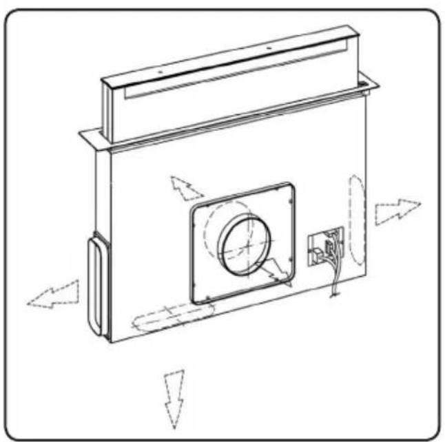
- Fit the hood into the hole made, by inserting it from above, as shown in (Fig. 2).
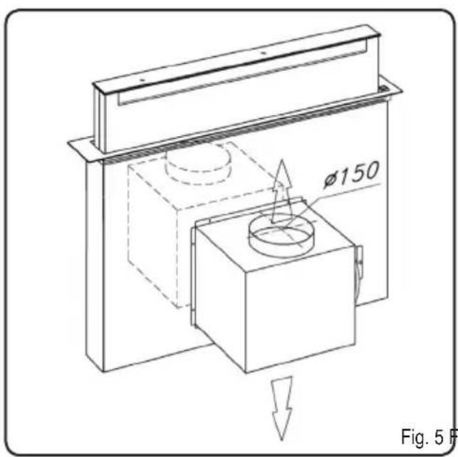
In the case of internal motor version, it is necessary to fit the power pack by directing the air outlet towards the desired position, either downwards or upwards (Fig. 5). The motor can be fit on both the front and rear side of the downdraft. Once fitting the motor, the air-outlet piping can be fit.
In the case of external motor version, the power pack (external motor) shall be positioned in a suitable place and the air exhaust piping shall be fit. Install the air outlet piping between the external motor and the downdraft. Select the air-out let among the 5 possible options (Fig.6) and fit the pipe fitting supplied.
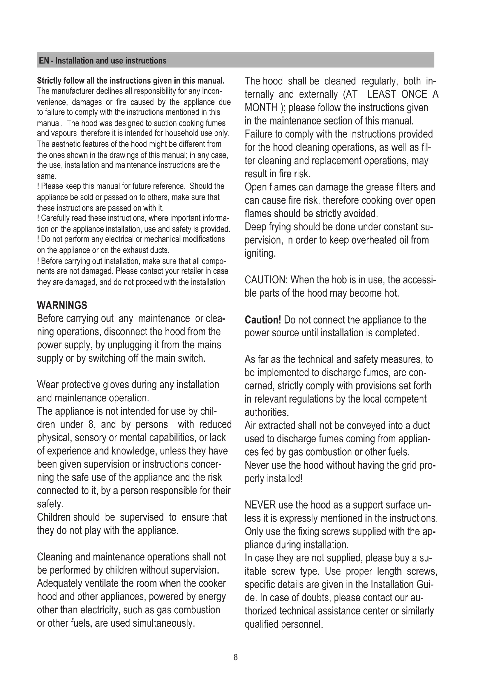
After completing installation and connecting the appliance to the power supply, lift up the downdraft by pushing on the front piece seat, as shown in fig. 7.
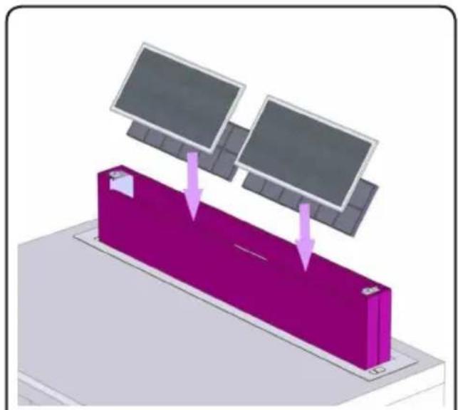
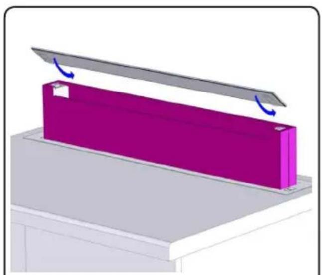
Then fit the charcoal filters, if the product is in the filtering version, ( charcoal filters are not supplied with the appliance and are purchasable in a specific kit), the grease filters (see fig. 8), and finally the front glass as shown in fig. 9; make sure to fit the glass properly, as shown in fig. 10.
- Place the metal box containing the electronic components in an easily reachable area for possible technical assistance operations, by connecting the electric connectors of the box to the hood (fig. 11).
How the hood works
It is necessary to open the extractable unit in order to ensure the appliance normal operation, by following these steps.
Push the glass downwards, as shown in fig. 12; the glass will be released and will open.
Following the extractable unit opening, it will be possible to operate the suction motor by using the push-button panel, as follows.
To close the extractable unit, push on the front glass until the extractable unit is completely closed.
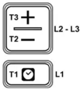
T1. Timer ON/OFF key: press it to set the automatic switching off:
Speed 1: 20 minutes
Speed 2: 15 minutes
Speed 3: 10 minutes
High Speed : 5 minutes
T2. Key to decrease the aspiration speed (power).
OFF 1: press it multiple times, in order in order to reduce the aspiration speed until the hood is turned off.
OFF 2: hold it down for a prolonged period of time, at any speed.
T3. ON /aspiration speed (power) increase (1-2-3-High speed) key.
The High speed lasts about 5 minutes: after that speed 2 is automatically set.
Filter saturation indicator
The hood displays when it is necessary to carry out maintenance on the filters:
Grease filter (about every 40 hours of use): all the Leds with blue light will flash
Activated charcoal filter (about every 160 hours of use): all the Leds with blue light, leds L2 and L3 will flash.
Filter saturation resetting
After performing the filter maintenance, press keys T1 and T3, for a prolonged period of time, Leds L1, L2 and L3 will flash shortly with a blue light, and then will turn off.
Enabling the activated charcoal filter saturation indicator.
This indicator is usually disabled. Follow this procedure to enable it:
With the hood turned off, press and keep T1 and T2 keys pressed simultaneously for a prolonged period of time: at first L1 will light up, followed by L2 and L3; then, when the keys are released, leds L2 and L3 will flash shortly to confirm that activation has been completed.
Disabling the activated charcoal filter saturation LED: repeat the above mentioned procedure; at first leds L1, L2 and L3 light up simultaneously; then, when the keys are released, leds L2 and L3 will turn off to confirm that deactivation has been completed.
MAINTENANCE
Grease filter
It captures grease particles deriving from cooking.
It shall be cleaned once a month (or when the filter saturation indicator - in case your model is equipped with this feature- displays that it is necessary), with mild detergent, by washing it by hand or in the dishwasher at low temperature and with a short cycle.
The metal grease filter may fade if washed in the dishwasher, but its filtering characteristics will remain unchanged.
Activated charcoal filter (Filtering Version only)
It captures unpleasant odours deriving from cooking.
The charcoal filter saturation depends on the usage, on the cooking style and on how often the grease filter is cleaned. In any case, the filter shall be replaced at least every four months.
After removing the grease filters, it is possible to fit the charcoal filters (Fig. 8).