CVS 651 Bp - Sweeper Kärcher - Free user manual and instructions
Find the device manual for free CVS 651 Bp Kärcher in PDF.
| Product type | Sweeping vacuum |
| Brand | Kärcher |
| Model | CVS 651 Bp |
| Intended use | Dry cleaning of carpets and textile indoor floors, professional use |
| Dimensions (L × W × H) | 980 × 675 × 1070 mm |
| Empty weight | 39 kg |
| Maximum permissible total weight | 54 kg |
| Power supply | Lithium-ion battery 36 V, 7.5 Ah (model Battery Power+ 36/75) |
| Runtime | Up to 60 minutes |
| Working width | 450 mm (with side brush: 625 mm) |
| Max. area performance | 2500 m²/h |
| Dust bin volume | 20 L (max. load 15 kg) |
| Filtration | Pleated flat filter made of polyester felt with PTFE coating (dust class M), pre-filter |
| Sound power level | 72 dB(A) |
| Hand-arm vibration | < 2.5 m/s² |
| Main functions | Antistatic roller brush with pressure adjustment, side brush, automatic pre-filter cleaning, LED pressure indicator, On/Off switch |
| Maintenance and cleaning | Clean dust filter every ~10 h, replace if damaged; check and replace brushes and roller according to wear; adjust sealing strips |
| Safety | Hood switch (stops if open), On/Off switch, overload protection (electronic), instructions for slopes and hazardous materials |
| Spare parts and repairability | Original Kärcher accessories (brushes, filter, bags, battery, charger); authorized after-sales service |
| General information | Warranty according to country conditions; do not dispose with household waste; EU conformity |
Frequently Asked Questions - CVS 651 Bp Kärcher
User questions about CVS 651 Bp Kärcher
0 question about this device. Answer the ones you know or ask your own.
Ask a new question about this device
Download the instructions for your Sweeper in PDF format for free! Find your manual CVS 651 Bp - Kärcher and take your electronic device back in hand. On this page are published all the documents necessary for the use of your device. CVS 651 Bp by Kärcher.
USER MANUAL CVS 651 Bp Kärcher
natural_image
3D rendering of a gray cleaning or cleaning power cleaner with yellow buttons and a blue handle (no visible text or symbols)Deutsch 2
English 10
Français 18
Italiano 26
Nederlands 34
Español 42
Português 50
Dansk 58
Norsk 66
Svenska 73
Suomi 81
Ελληνικά 89
Türkçe 97
Русский 105
Magyar 113
Čeština 121
Slovenščina 129
Polski 137
Românește 145
Slovenčina 153
Hrvatski 161
Srpski 169
Български 177
Eesti 185
Latviešu 193
Lietuviškai 201
Українська 209
中文 217
العربيya 232

Register your product
www.kaercher.com/welcome

001

59693650

(10/22)
Inhalt
text_image
Labeled diagram of a KAROL GPS cleaning machine showing numbered components and control panel interfacenatural_image
3D diagram of a computer monitor with a red arrow indicating rotation or change, showing the blade and handle mechanism (no text or symbols present)natural_image
Black metal toolbox covered with plastic wrap, no visible text or symbolstext_image
Diagram of a cleaning machine with numbered components and labeled partsnatural_image
3D mechanical component diagram showing a shaft and housing with numbered annotations (1 and 2), no readable text or symbols beyond labels.text_image
Technical diagram of a mechanical assembly with numbered components, likely illustrating a component assembly or inspection.①Verschlüsse (2x)
text_image
Technical diagram of a mechanical assembly with labeled components 1, 2, and 3text_image
Technical diagram of a mechanical gear assembly with numbered parts labeled 1, 2, and 3text_image
Technical diagram of a cleaning or dust cleaning machine with numbered parts labeled 1 to 4
H. Jenner
Chairman of the Board of Management

S. Reiser
Director Regulatory Affairs & Certification
71364 Winnenden (Germany)
Tel.: +49 7195 14-0
Fax: +49 7195 14-2212
Winnenden, 2020/12/01
Contents
General notes 10
Intended use 10
Function 11
Safety instructions 11
Description of the device.... 12
Initial startup 13
Operation 13
Transport.... 14
Storage 14
Care and maintenance 14
Troubleshooting guide 16
Accessories / spare parts.... 17
Technical data.... 17
Declaration of Conformity 17
General notes
Read these original instructions and the safety instructions chapter before using the device for the first time. Act in accordance with them.
Keep them safe for future reference or for future owners.
Checking the delivery
Please report any defects or shipping damage identified on the vehicle when it is handed over directly to your dealer or department store.
Environmental protection

The packing materials can be recycled. Please dispose of packaging in accordance with the environmental regula-
tions.

Electrical and electronic appliances contain valuable, recyclable materials and often components such as batteries, rechargeable batteries or oil, which - if handled or disposed of incorrectly - can pose a potential threat to human health and the environment. However, these components are required for the correct operation of the appliance. Appliances marked by this symbol are not allowed to be disposed of together with the household rubbish.
Notes on the content materials (REACH)
Current information on content materials can be found at: www.kaercher.com/REACH
Warranty
The warranty conditions issued by our relevant sales company apply in all countries. We shall remedy possible malfunctions on your appliance within the warranty period free of cost, provided that a material or manufacturing defect is the cause. In a warranty case, please contact your dealer (with the purchase receipt) or the next authorised customer service site.
(See overleaf for the address)
Accessories and spare parts
Only use original accessories and original spare parts. They ensure that the appliance will run fault-free and safely.
Information on accessories and spare parts can be found at www.kaercher.com.
Hazard levels
DANGER
- Indication of an imminent threat of danger that will lead to severe injuries or even death.
△WARNING
- Indication of a potentially dangerous situation that may lead to severe injuries or even death.
△CAUTION
- Indication of a potentially dangerous situation that may lead to minor injuries.
ATTENTION
- Indication of a potentially dangerous situation that may lead to damage to property.
Symbols on the device
△DANGER
Risk of burns from hot surfaces
Allow the appliance to cool down sufficiently before working on it or opening bonnets.

△DANGER
Risk of injury and crushing due to moving machine parts and circulating drive belts.
Wait until all parts of the appliance have come to a complete standstill before opening the bonnet and do not reach inside the appliance during operation.

Roller brush contact pressure display (sweeping pattern)
Raise roller brush
Lower roller brush
Lower side brush
Raise side brush

The unit's scope of delivery includes a flat fold filter made of polyester fleece with PTFE coating (dust class M).
Intended use
This battery-operated device is a sweeper for cleaning carpets and various textile floors indoors. It has an antistatic roller brush and a built-in dust filter.
This device is only intended for dry application.
The sweeper is designed for commercial use.
Only use the sweeper in accordance with the information in these operating instructions. Any other use is considered as improper use. The manufacturer assumes no liability for any resultant damage. The user is solely responsible for the risk.
No modifications must be made to the sweeper.
Only the areas approved by the company or the company's representatives must be driven on and cleaned.
Foreseeable misuse
This device is only intended for dry application and must not be used or stored outside in wet conditions.
The device is not designed for driving on slopes.
Never sweep or suction up explosive liquids, gases, non-diluted acids or solvents (e.g. petrol, paint thinner, heating oil) because they form explosive vapours or mixtures in conjunction with the suction air.
Never sweep or suction up acetone, non-diluted acids or solvents, as they will corrode and damage the materials used on the device.
Never sweep or suction up reactive metal dusts (e.g. aluminium, magnesium, zinc). They form explosive gases in conjunction with highly alkaline or acidic cleaning agents.
Do not sweep or suction up burning or smouldering objects.
There is a risk of fire.
Do not sweep up any harmful substances.
Standing in hazard zones is prohibited. Operation in explosive spaces is prohibited.
This device must not be used to push/pull or transport objects.
Suitable surfaces for sweeping
Large textile areas e.g. in:
- Offices
Hotels - Shops
- Casinos
- Airports
- Tennis halls
• Exhibition halls
Function
The sweeper operates using the direct-throw principle.
- The rotating side brushes clean corners and edges of the sweeping surface and convey the waste into the path of the roller brush.
- The rotating roller brush conveys the waste directly into the waste container.
- The dust swirled up in the waste container is separated by a dust filter and a pre-filter, and the blower suctions the filtered clean air.
- The pre-filter is cleaned automatically after a specified time when the device is switched on and during work.
- The protruding rear wheels allow easy transportation on stairs.
- The collected dirt is transported into the waste container. The waste container can optionally be equipped with a dust bag.
Safety instructions
Safety instructions for operation
△ WARNING • Only use the device for its proper use. Take into account the local conditions and beware of third parties, in particular children, when working with the device. • Always protect the device from sun, rain and other weather conditions, both during operation and when it is not in use. Store the device in a dry and sheltered room. This device is only intended for dry application and must not be used or stored outside in wet conditions.
- Check the device with the operating devices to make sure it is in proper condition and operational safe and reliable. If it is not in perfect condition, you must not use it. • Adhere to the respective safety regulations in hazard zones (e.g. service stations). Never operate the device in explosive spaces. • The device is not intended for use by persons with restricted physical, sensory or mental abilities or those lacking in experience and / or lacking in knowledge. • Only people who have been instructed on how to use the device, or have proven their ability to operate it, and have been explicitly instructed to use it, must use the device. ATTENTION • Before starting work, the operator must check whether the safety devices have been attached properly and are fully functional. • The device operator is responsible for accidents with other people and their property. WARNING • The operator must wear close-fitting clothing and sturdy footwear. Avoid loose-fitting clothing. • Children must be supervised to prevent them from playing with the appliance. • Children and adolescents must not operate the device. ATTENTION • Check the immediate vicinity before setting off (e.g. children). Make sure you have a sufficient view. CAUTION • Do not use the device in areas in which there is a possibility of being struck by falling objects.
Description of the device
The device is available in 2 different versions:
• CVS 65/1 Bp Pack (1.517-300.0)
Battery and charger included in the scope of delivery
• CVS 65/1 Bp (1.517-301.0)
Without battery and charger
Device illustration
text_image
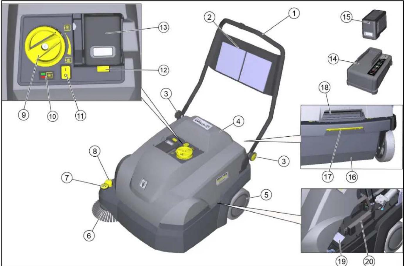
Labeled diagram of a KAROL cleaning machine showing numbered components and control panel interface①Push handle
②Storage net (not for replacement battery)
③Star screws for push handle adjustment (2x)
④Cover
⑤Rear wheel (2x)
⑥Right side brush
⑦Side brush adjustment
Adjust contact pressure
- Raise the side brush
⑧Lower the side brush
⑨Roller brush contact pressure adjustment (sweeping pattern)
⑩ Roller brush contact pressure display
.ED does not light up: Lower the roller brush further
- Green LED: correct adjustment
- LED red: Raise the roller brush
⑪On/off switch
⑫Battery release mechanism
⑬Battery compartment
⑭Charger, "Battery Power+"
Only included in the scope of delivery for the CVS 65/1 Bp Pack
⑮ "Battery Power+ 36/75" rechargeable battery
- Only included in the scope of delivery for the CVS 65/1 Bp Pack
⑯Removable waste container
- A dust bag (option) can be inserted into the waste container.
⑰ Waste container release mechanism
18Device cover recessed grip
⑲Type plate
⑳ Compartment for replacement battery (with retaining strap)
Safety devices
Safety devices protect the user and may not taken out of operation or functionally circumvented.
Adhere to the safety instructions in the chapters!
Cover switch
The cover switch prevents the device from starting when the device cover is open.
On/off switch
The on/off switch prevents the device from starting up unintentionally. Switch off the on/off switch when parking the device or in the event of danger.
Electronics
If the roller brush is overloaded, the electronics switch off the device and the LED flashes.
In this case, switch off the device at the on/off switch and before switching it back on, turn the roller brush all the way up using the contact pressure adjustment.
Initial startup
Adjusting the push handle
Note
The push handle is folded down on delivery of the device. It can be adjusted to 3 different heights for work.
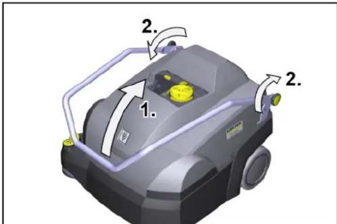
text_image
1. 2. 2.-
Fold the push handle up into the desired position. Make sure that the grooves engage correctly in the bolts (fixing).
-
Tighten the star screws hand-tight.
Opening/closing the cover
△CAUTION
Risk of crushing fingers
Only use the recessed grip provided to open and close the cover.
ATTENTION
Risk of burns from a hot drive motor
The drive motor can get hot during operation.
Do not touch hot surfaces. Pay attention to the warning symbols.
Note
It is necessary to open the cover:
• For maintenance and cleaning work
• For changing/cleaning the dust filter and pre-filter
- For storing a replacement battery.
-
Opening the cover: Grasp the device cover by the recessed grip and slowly swivel it forward. A strap holds the device cover.
-
Closing the cover: Slowly swivel the device cover back.
Installing the side brush
The side brush is supplied with the device on delivery and must be attached to the device before initial startup.
See chapter "Changing the side brushes".
Charging/inserting the battery
Charge the battery before initial startup.
The corresponding description can be found in the separate operating instructions for the rechargeable battery and charger.
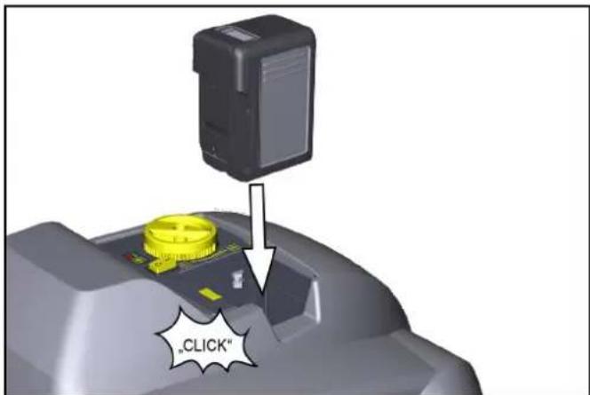
text_image
"CLICK"1 Insert the charged battery into the battery compartment, push it in up to the stop and snap it in place.
Dust bag (option)
A dust bag can be inserted into the waste container for easy and safe disposal of the waste.
- Actuate the waste container lock (pull backwards).
- Tilt the waste container to the rear and pull it out.
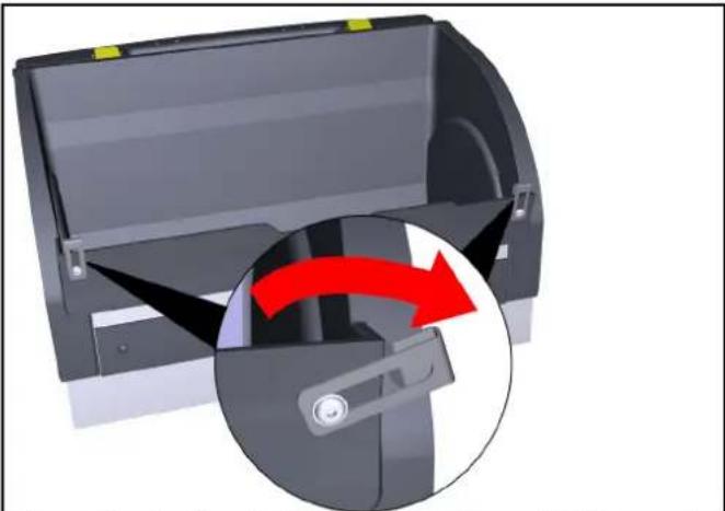
- Fold the fastening clips on the front of the waste container outwards.
natural_image
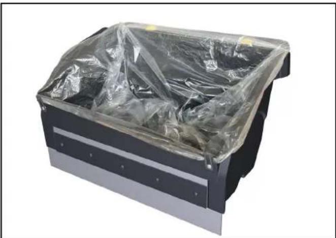
3D diagram of a mechanical device with a red arrow indicating rotation or movement, showing internal components and a close-up view (no text or symbols)- Insert the dust bag in the waste container and fold it over the edge.
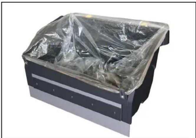
natural_image
Black metal toolbox covered with plastic wrap, no visible text or symbols- Close the fastening clip again.
- Insert the waste container and push it all the way forward.
- Check whether the waste container has clicked into place.
Operation
Information on sweeping operation
△CAUTION
Risk of damage
Carry out cleaning work in the forward travel direction.
Do not carry out any cleaning work with the waste container removed.
Do not let the device run in place with the roller brush switched on.
Do not sweep parcel tape, pieces of string or similar items (damage to the sweeping mechanics).
Note
Adjust the sweeping speed to the conditions in order to achieve optimum cleaning results.
Sweeping with roller brush and side brush
text_image
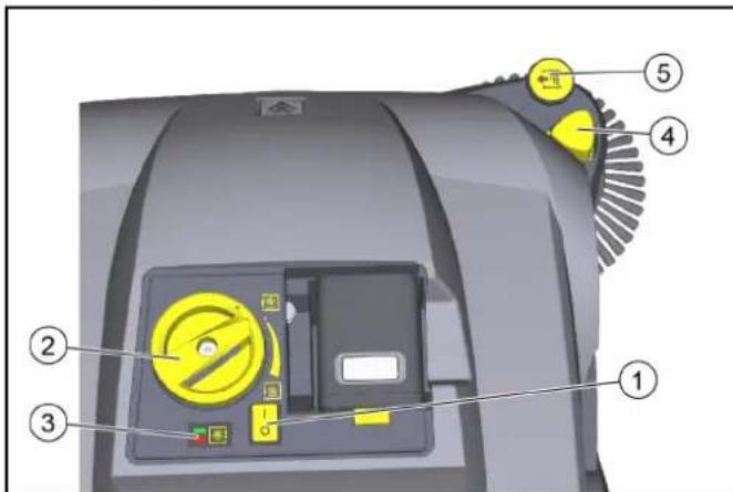
Diagram of a cleaning machine with numbered components and labeled parts in Chinese①On/off switch
②Roller brush contact pressure adjustment (twist grip)
③Roller brush contact pressure display
- LED does not light up: Lower the roller brush further
– Green LED: correct adjustment - LED red: Raise the roller brush
④Lower the side brush
⑤Side brush adjustment
- Adjust contact pressure
- Raise the side brush
- Switch on the device at the on/off switch (position I). a Roller brush and side brushes rotate.
- Push the device forward by the push handle and start cleaning. Use the roller brush contact pressure adjustment, depending on the textile pile.
a To adjust, lift the twist grip, then turn.
b The correct contact pressure is indicated by a green LED.
- For cleaning close to the edge, lower the side brushes by pressing the side brush lowering button.
a If necessary, use the side brush adjustment and set the contact pressure. - To pick up larger objects (20 mm), press the push handle down a little so that the roller brush can move the objects into the waste container.
- An automatic cleaning of the pre-filter ensures continuous work.
- Always recharge the rechargeable batteries in good time. a During the sweeping operation, the display in the battery shows the remaining time in minutes.
b When the device is switched off, the battery charge is displayed in%.
Stopping and parking the device
- To finish the work, switch off the device with the on/off switch (position 0).
- Park the device on a level surface.
- Lift the twist grip of the roller brush and turn it anticlockwise all the way up.
- Pull the lowered side brush up on the adjustment. The side brush locks into place.
- Empty the waste container.
- Clean the dust filter and pre-filter.
- Charge the battery.
Emptying the waste container
natural_image
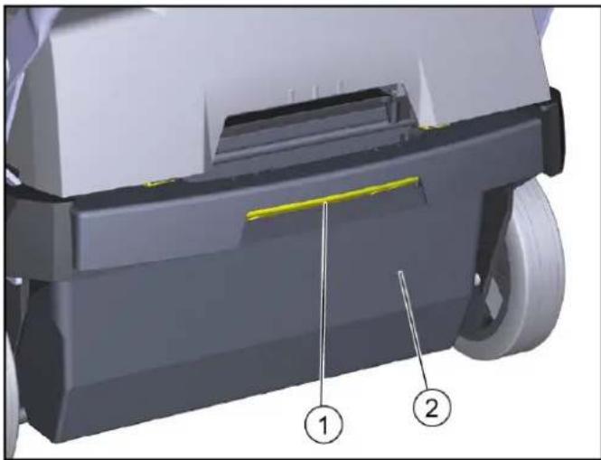
3D mechanical component diagram showing a shaft and housing with labeled parts (1 and 2), no readable text or symbols beyond labels.① Waste container lock
② Waste container
- Actuate the waste container lock (pull backwards).
- Tilt the waste container to the rear and pull it out.
- Empty the waste container or remove the dust bag (option).
- Insert the waste container and push it all the way to the front. If necessary, insert the dust bag (option) beforehand as described in the chapter "Dust bag (option)".
- Check whether the waste container has clicked into place.
Transport
△CAUTION
Risk of injury and damage
Be aware of the weight of the device during transportation.
- Switch off the device at the on/off switch.
- Lift the twist grip of the roller brush and turn it anticlockwise all the way up.
- Secure the device to the wheels with wedges.
- Secure the device with ropes or lashing straps. a At the front of the frame under the device cover. b At the rear in the push handle attachment area.
- When transporting in vehicles, secure the device against slipping and tipping over according to the applicable guidelines.
Storage
△WARNING
Risk of injury and damage
Note the weight of the device.
- Place the device in a dry, protected place on an even surface.
- Remove the battery.
a Observe the battery storage instructions in the operating instructions.
- Clean the device inside and out.
- Lift the twist grip of the roller brush and turn it anticlockwise all the way up.
Care and maintenance
General notes
△DANGER
Risk of accidents and injuries due to unintentional movement of the device
Switch off the device and remove the rechargeable battery before carrying out any care and maintenance work.
Cleaning the device
△CAUTION
Risk of short circuits due to water stream
Do not clean the device with a hose or high-pressure water jet.
△DANGER
Health risk from dust
Wear a dust mask and safety goggles when cleaning with compressed air.
ATTENTION
Risk of damage to the surfaces
Do not use any scouring agents or aggressive cleaning agents for cleaning purposes.
-
Blow out the inside of the device with compressed air.
-
Clean the inside and outside of the device with a damp cloth, soaked in mild washing lye.
Maintenance intervals
Maintenance by the customer
Note
All servicing and maintenance work must be performed by a qualified specialist. If necessary, you can consult a Kärcher specialist dealer at any time.
• Daily maintenance
1 Check the roller brush and side brush for any tangled pieces of tape.
2 Check that the control elements are fully functional.
• Weekly maintenance
1 Check the moving parts to make sure that they move smoothly.
2 Check the sealing strips in the sweeping area for correct adjustment and for wear.
3 Check the roller brush and side brush for wear.
4 Check the filter box, clean the pre-filter if necessary.
5 Check the dust filter, clean if necessary (depending on frequency of use approx. every 10 hours).
• Monthly maintenance
1 Remove the roller brush and remove dirt from the drive journal (see chapter "Checking/changing the roller brush")
• Maintenance after wear
1 Adjust or change sealing strips.
2 Replace the roller brush.
3 Replace the side brush.
Note
See chapter "Maintenance work" for descriptions.
Maintenance by Customer Service
Note
To ensure the validity of warranty claims, all servicing and maintenance work during the warranty period must be performed by an authorised Customer Service department.
1 Have maintenance work carried out according to the inspection checklist.
Maintenance work
Clean/replace the dust filter
△DANGER
Health risk from dust
Wear a dust mark and safety goggles when working on the filter system.
text_image
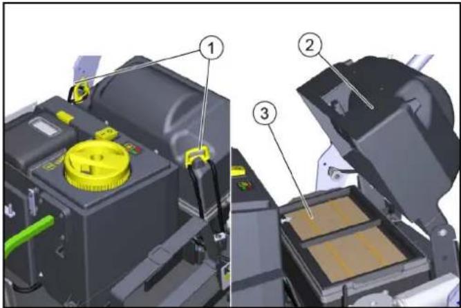
Technical diagram showing three labeled components of a mechanical device, including a yellow component with yellow lid and green cable.①Locks (2x)
②Filter housing cover
③Filter box
- Park the device and switch off at the on/off switch.
- Open the cover.
- Open the locks.
- Swing the cover upwards.
- Remove the filter box with the dust filter upwards.
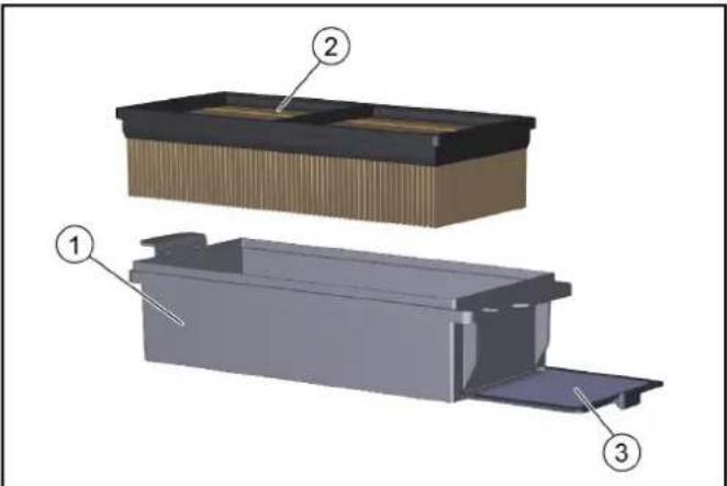
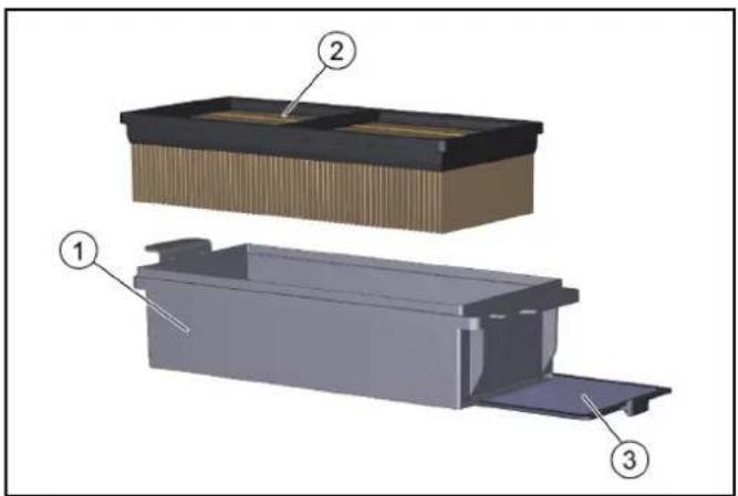
text_image
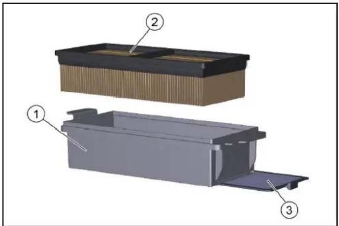
Technical diagram of a mechanical assembly with labeled components 1, 2, and 3①Filter box
② Dust filter
③Removable pre-filter
- Check dust filter and pre-filter.
a To clean, vacuum the dust filter or knock it out together with the filter box (do not wash out).
b Pull out the pre-filter and clean it.
- Check and clean the filter scraper.
- Use a new dust filter or fit a new pre-filter in the filter box if it is damaged or heavily soiled.
- Note the installation direction of the filter box during installation.
Replacing the side brush
Changing the side brush when the device is tilted is described.
ATTENTION
Risk of injury and damage
Remove the rechargeable battery and the sweep container before tilting the device.
Secure the tipped device before changing the side brush.
text_image
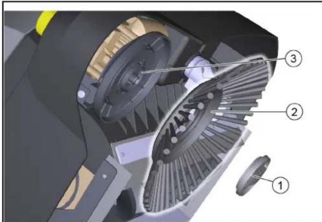
Technical diagram of a mechanical gear assembly with numbered parts labeled 1, 2, and 3①Lock
②Side brushes
③Mount
- Remove the waste container.
- Take the battery out.
- Tilt the device to the rear and secure it against tipping down.
- Unscrew the lock on the underside.
a Open: Turn anticlockwise
b Close: Turn clockwise
- Remove the side brush.
- If necessary, clean the mount.
- Connect the new side brush to the mount and fasten it in place with the lock.
Check / change roller brush
Check and change the roller brush with the device tilted.
ATTENTION
Risk of injury and damage
Remove the rechargeable battery and the sweep container before tilting the device.
Secure the tipped device before replacing the roller brush.
When inserting the new roller brush, make sure that no bristles are caught in the hole of the roller brush swing arm.

text_image
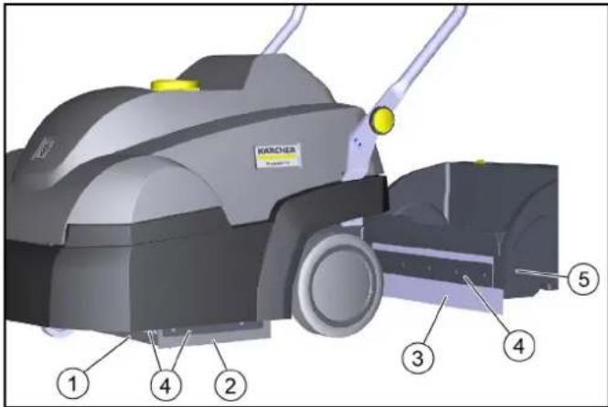
Technical diagram of a mechanical device with numbered parts labeled 1 to 4, showing internal components and motion indicators.① Bearing shell
②Roller brush
③Drive journal
④Distance between sealing strip and retaining plate
- Target value: 28–30 mm
- Take the battery out.
- Remove the waste container.
- Tilt the device to the rear and secure it against tipping down.
- Remove the wrapped ribbons and cords from the roller brush.
- Remove dirt from the drive journal.
- To change the roller brush, grasp the roller brush by the base body. press to the left and pull out downwards.
- Fit the new roller brush on the drive journal (left). On the opposite side, latch the bearing shell in the hole of the rotary brush swing arm.
- When the device is tilted, check the adjustment of the front sealing strip, readjust if necessary.
Replacing / setting the sealing strips
| Sealing strips Setting values | |
| Side sealing strips Distance from | floor 1 - 2 mm |
| Front sealing strip | Distance between sealing strip and retaining plate 28–30 mm |
| Rear sealing strip Not adjustable |
text_image
WARCHER ① ④ ② ③ ④ ⑤①Front sealing strip
②Side sealing strip
③Rear sealing strip (not adjustable)
④Fastening
⑤ Waste container
- Unfasten the fastening of the sealing strips.
- Set the sealing strip by shifting it in the elongated holes.
a Refer to the table for the values.
- Once the settings are correct, fasten the sealing strips.
Troubleshooting guide
Note
Contact the Customer Service department in the case of any faults not listed!
Roller brush/side brush not running or running incorrectly
- Switch off the on/off switch (position I).
● Charge the rechargeable battery.
● Latch the rechargeable battery in place correctly.
● Electronics switched off the device due to overload (LED flashes). When switching on again, note:
a Switch off the device using the on/off switch.
b Raise the roller brush by lifting the twist grip and turning it all the way up anticlockwise.
c Switch on the device at the on/off switch.
- Check the roller brush / side brush for any tangled pieces of tape.
- Check the belt.
● Fully close the device cover (cover switch).
Dust when sweeping / insufficient suction power
● Empty the waste container.
- Check/replace seals on filter box and waste container.
- Check/clean/replace dust filter and pre-filter.
a Check that the dust filter and pre-filter are correctly seated.
b Clean the dust filter and pre-filter if they are lightly soiled.
c In case of damage or heavy soiling, replace the dust filter and pre-filter.
- Check the sealing strips for wear / set / replace them.
- Blower defective, contact customer service.
Sweeping performance not satisfactory
- Correctly set the sweeping pattern of the roller brush and side brush with the adjustment device.
- Roller brush and side brush are too worn, replace them.
- Check the sealing strips for wear, adjust or replace them if necessary.
Accessories / spare parts
The following is an overview (excerpts thereof) of wear parts or optionally available accessories.
| Accessories Description | Order no. | |
| Side brush For interior textile coverings | 2.884-355.0 | |
| Roller brush For interior textile coverings | 2.886-002.0 | |
| Dust filter Flat fold filter (PTFE) 6.907-449.0 | ||
| Pre-filter 5.745-280.0 | ||
| Dust bag 10 dust bags in a set 2.884-358.0 | ||
| Replacement battery, “Battery Power+ 36/75 DW” | High performance rechargeable battery 36 V, 7.5 Ah | 2.445-043.0 |
| Charger, “Battery Power+” | Quick charger, 36 V *EU | 2.445-045.0 |
Technical data
Device performance data
| Operation duration with fully loaded bat-tery | Minutes | Up to 60 |
| Working width | mm | 450 |
| Working width with 1 side brushes | mm 625 |
Theoretical surface performance
| Surface performance (max) | m^2/h | 2500 |
| Battery | ||
| Battery type | Lithium-ion | |
| Battery capacity | Ah | 7,5 |
| Working voltage of the battery | V | 36 |
Ambient conditions
| Ambient temperature | °C | 0 bis +40 |
| Humidity, non-condensing | % 0 - 90 |
Dimensions and weights
| Length | mm | 980 |
| Width | mm | 675 |
| Height | mm 1070 | |
| Net weight (transport weight) | kg | 39 |
| Approved total weight | kg | 54 |
| Width of roller brush | mm 450 | |
| Diameter of roller brush | mm | 230 |
| Diameter of side brush | mm | 250 |
Waste container
| Waste container volume | I (kg) | 20 (15) |
Filter and suction system
| Filter system | Flat fold filter |
| Filter area | m^2 | 0,95 |
| Dust class | M |
Determined values in acc. with EN 60335-2-72
| Hand-arm vibration value | m/s2 | < 2,5 |
| Sound pressure level L_pA | dB(A) | 56 |
| Uncertainty K_pA | dB(A) | 2 |
| Sound power level L_WA + K uncertainty. | dB(A) | 72 |
| WA | ||
| Uncertainty K_WA | dB(A) | 2 |
Subject to technical modifications.
Declaration of Conformity
EU- Declaration of Conformity
We hereby declare that the machine described below complies with the relevant basic safety and health requirements in the EU Directives, both in its basic design and construction as well as in the version placed in circulation by us. This declaration is invalidated by any changes made to the machine that are not approved by us.
Product: Sweeper vacuum
Type: 1.517-300.0 | 1.517-301.0
Currently applicable EU Directives
2006/42/EC (+2009/127/EC)
2014/30/EU
2000/14/EC
2011/65/EU
Harmonised standards used
EN 60335-1
EN 60335-2-29
EN 60335-2-72
EN 62233: 2008
EN 55014-1: 2017 + A11: 2020
EN 55014-2: 2015
EN 61000-3-2: 2014
EN 61000-3-3: 2013
EN 61000-6-2: 2005
EN IEC 63000: 2018
Applied conformity evaluation method
2000/14/EG: Annex V
Sound power level dB(A)
Measured: 70
Guaranteed: 72
The signatories act on behalf of and with the authority of the company management.

H. Jenner
Chairman of the Board of Management

S. Reiser
Director Regulatory Affairs & Certification
Documentation supervisor:
S. Reiser
Alfred Kärcher SE & Co. KG
Alfred-Kärcher-Str. 28 - 40
71364 Winnenden (Germany)
Ph.: +49 7195 14-0
Fax: +49 7195 14-2212
Winnenden, 2020/12/01
Declaration of Conformity (UK)
We hereby declare that the product described below complies with the relevant provisions of the following UK Regulations, both in its basic design and construction as well as in the version put into circulation by us. This declaration shall cease to be valid if the product is modified without our prior approval.
Product: Sweeper vacuum
Type: 1.517-300.0 | 1.517-301.0
Currently applicable UK Regulations
S.I. 2008/1597 (as amended)
S.I. 2016/1091 (as amended)
S.I. 2001/1701 (as amended)
S.I. 2012/3032 (as amended)
Designated standards used
EN 60335-1
EN 60335-2-29
EN 60335-2-72
EN 62233: 2008
EN 55014-1: 2017 + A11: 2020
EN 55014-2: 2015
EN 61000-3-2: 2014
EN 61000-3-3: 2013
EN 61000-6-2: 2005
EN IEC 63000: 2018
Applied conformity assessment procedure
S.I. 2001/1701 (as amended): Schedule 8
Sound power level dB(A)
Measured: 70
Guaranteed: 72
The undersigned act on behalf and under the power of attorney of the company management.

H. Jenner
Chairman of the Board of Management

S. Reiser
Director Regulatory Affairs & Certification
Documentation supervisor:
S. Reiser
Alfred Kärcher SE & Co. KG
Alfred-Kärcher-Str. 28 - 40
71364 Winnenden (Germany)
Ph.: +49 7195 14-0
Fax: +49 7195 14-2212
Winnenden, 2020/12/01
Contenu
text_image
Labeled diagram of a cleaning or cleaning machine with numbered components and control panel interfacenatural_image
3D diagram of a mechanical device with a red arrow indicating rotation or change, showing internal components and a close-up view (no text or symbols)natural_image
Exterior view of a black metal toolbox covered with plastic wrap (no text or symbols visible)text_image
Diagram of a washing machine with numbered components and labeled parts, including buttons and gauges.natural_image
3D mechanical component diagram showing a shaft and housing with numbered annotations (1 and 2), no readable text or symbols beyond labels.text_image
Technical diagram of a mechanical assembly with numbered components, likely illustrating a component assembly or inspection.①Fermetures (2x)
text_image
Technical diagram of a mechanical assembly with labeled components 1, 2, and 3text_image
Technical diagram of a mechanical gear assembly with numbered parts labeled 1, 2, and 3text_image
Technical diagram of a cleaning or dust cleaning machine with numbered components labeled 1 to 42006/42/CE (+2009/127/CE)
2014/30/UE
2000/14/CE
2011/65/EU

H. Jenner
Chairman of the Board of Management

S. Reiser
Director Regulatory Affairs & Certification
71364 Winnenden (Germany)
text_image
Technical diagram of a KAROL cleaning machine with numbered components and control panel interfacenatural_image
3D diagram of a mechanical component with a red arrow indicating rotation or adjustment, showing internal structure and mounting points (no text or symbols)natural_image
Black metal toolbox covered with plastic wrap, no visible text or symbolstext_image
Diagram of a cleaning machine with numbered components and labeled parts in Chinesenatural_image
3D mechanical component diagram showing a base with two labeled parts (① and ②), no readable text or symbols present.text_image
Technical diagram of a mechanical assembly with numbered components, likely for assembly or maintenance instructions.①Chiusure (2x)
text_image
Technical diagram of a mechanical assembly with labeled components 1, 2, and 3①Cartuccia filtrante
②Filtro antipolvere
text_image
Technical diagram of a mechanical gear assembly with numbered parts labeled 1, 2, and 3text_image
Technical diagram of a cleaning or dust cleaning machine with numbered components labeled 1 to 4Chairman of the Board of Management

S. Reiser
Director Regulatory Affairs & Certification
71364 Winnenden (Germany)
Tel.: +49 7195 14-0
Fax: +49 7195 14-2212
Winnenden, 01/12/2020
Inhoud
text_image
Labeled diagram of a KAROL cleaning machine showing numbered components and control panel interface⑮Accu "Battery Power+ 36/75"
- Alleen in de leveringsomvang van CVS 65/1 Bp Pack inbegrepen
natural_image
3D diagram of a mechanical device with a red arrow indicating rotation or movement, showing internal components and a close-up view (no text or symbols)natural_image
Exterior view of a black metal toolbox covered with plastic wrap (no text or symbols visible)text_image
Diagram of a cleaning machine with numbered components and labeled partsnatural_image
3D mechanical component diagram showing a shaft and housing with numbered annotations (1 and 2), no readable text or symbols present.①Vergrendeling vuilreservoir
②Vuilreservoir
text_image
Technical diagram showing three labeled components of a mechanical device, including a yellow component with yellow lid and green cable.①Sluitingen (2x)
②Deksel filteromhulsel
③ Filtercassette
text_image
Technical diagram of a mechanical assembly with labeled components 1, 2, and 3① Filtercassette
②Stoffilter
text_image
Technical diagram of a mechanical gear assembly with numbered parts labeled 1, 2, and 3text_image
Technical diagram of a mechanical device with numbered parts labeled 1 to 4, showing internal components and motion path.Type: 1.517-300.0 | 1.517-301.0
Chairman of the Board of Management

S. Reiser
Director Regulatory Affairs & Certification
71364 Winnenden (Germany)
Tel.: +49 7195 14-0
Fax: +49 7195 14-2212
Winnenden, 2020/12/01
text_image
Labeled diagram of a KARAN cleaning machine with numbered components and control panel interface① Asa de empuje
natural_image
3D diagram of a computer monitor with a red arrow indicating rotation or change, showing the blade and keyway (no text or symbols present)natural_image
Exterior view of a black industrial machine casing covered with plastic wrap (no text or symbols visible)text_image
Diagram of a cleaning machine with numbered components and control panel labelsnatural_image
3D mechanical component diagram showing a shaft and housing with labeled parts (1 and 2), no readable text or symbols beyond labels.text_image
Technical diagram of a mechanical assembly with numbered components, likely illustrating a component assembly or manufacturing process.①Bloqueos (2)
②Tapa de la carcasa del filtro
③Cartucho filtrante
text_image
Technical diagram of a mechanical assembly with labeled components 1, 2, and 3①Cartucho filtrante
②Filtro de polvo
③Filtro previo, extraíble
text_image
Technical diagram of a mechanical assembly with numbered components labeled 1, 2, and 3①Cierre
②Cepillos laterales
③Alojamiento
text_image
Technical diagram of a mechanical device with numbered parts labeled 1 to 4, showing internal components and motion indicators.① Semicojinete
2006/42/CE (+2009/127/CE)
2014/30/UE
2000/14/CE
2011/65/UE
Chairman of the Board of Management

S. Reiser
Director Regulatory Affairs & Certification
71364 Winnenden (Germany)
Tel.: +49 7195 14-0
Fax: +49 7195 14-2212
Winnenden, 01/12/2020
Índice
text_image
Labeled diagram of a KAROL cleaning machine showing numbered components and control panel interface⑮Bateria "Battery Power+ 36/75"
- Apenas no volume do fornecimento de CVS 65/1 Bp Pack
natural_image
3D diagram of a mechanical device with a red arrow indicating rotation or movement, showing internal components and a close-up view (no text or symbols)natural_image
Exterior view of a black industrial machine casing covered with plastic wrap (no text or symbols visible)text_image
Diagram of a washing machine with numbered parts and control buttons, likely for industrial cleaning or inspection.natural_image
3D mechanical component diagram showing a shaft and housing with numbered annotations (1 and 2), no readable text or symbols beyond labels.①Bloqueio do depósito de detritos
②Depósito de detritos
text_image
Technical diagram of a mechanical assembly with numbered components, likely for assembly or maintenance instructions.①Fechos (2x)
②Tampa da caixa do filtro
③ Cassete filtrante
text_image
Technical diagram of a mechanical assembly with labeled components 1, 2, and 3text_image
Technical diagram of a mechanical gear assembly with numbered parts labeled 1, 2, and 3①Fecho
②Vassoura lateral
③Admissão
text_image
Technical diagram of a cleaning or cleaning machine with numbered parts labeled 1 to 4①Bucha de mancal
②Escova cilíndrica de varredura
- Verificar as correias.
2006/42/CE (+2009/127/CE)
2014/30/UE
2000/14/CE
2011/65/UE

H. Jenner
Chairman of the Board of Management

S. Reiser
Director Regulatory Affairs & Certification
text_image
Labeled diagram of a cleaning or cleaning machine with numbered parts and control panel interface①Skubbebøjle
⑮Batteri "Battery Power+ 36/75"
– Kun inkluderet i leverancen af CVS 65/1 R Bp Pack
⑯Affaldsbeholder, aftagelig
natural_image
3D mechanical component diagram showing a disassembly or assembly process with a red arrow indicating rotation (no text or symbols present)- Placer bortskaffelsesposen i snavsbeholderen, og smøg den ud over kanten.
natural_image
Black metal toolbox covered with plastic wrap, no visible text or symbolstext_image
Diagram of a cleaning machine with numbered components and labeled parts in Chinesenatural_image
3D mechanical component diagram showing a motor or gearbox assembly with labeled parts (1 and 2), no readable text or symbols beyond labels.text_image
Technical diagram of a mechanical assembly with numbered components, likely illustrating a component assembly or inspection.①Låse (2x)
②Filterhusdæksel
③Filterkassette
text_image
Technical diagram of a mechanical assembly with labeled components 1, 2, and 3①Filterkassette
②Støvfilter
③Aftageligt forfilter
text_image
Technical diagram of a mechanical gear assembly with numbered parts labeled 1, 2, and 3①Lukning
②Sidekost
③Holder
- Fjern snavsbeholderen.
- Fjern batteriet.
- Vip maskinen bagud, og sørg for at sikre den mod at vippe ned igen.
- Drej läseskruen på undersiden ud.
a For at abne: drej mod uret
b For at lukke: drej med uret
text_image
Technical diagram of a cleaning or dust cleaning machine with numbered components labeled 1 to 4Type: 1.517-300.0 | 1.517-301.0
2006/42/EF (+2009/127/EF)
2014/30/EU
2000/14/EF
2011/65/EU

H. Jenner
Chairman of the Board of Management

S. Reiser
Director Regulatory Affairs & Certification
71364 Winnenden (Germany)
Tlf.: +49 7195 14-0
Fax: +49 7195 14-2212
Winnenden, 2020/12/01
Indhold
Generelle merknader 66
Forskriftsmessig bruk.... 67
Funksjon 67
www.kaercher.com/REACH
Garanti
Egnede overflater for feiing
Store tekstilområder f.eks. i:
- Kontorer
- Hoteller
- Butikker
- Kasinoer
- Flyplasser
- Tennishaller
- Messehaller
Funksjon
text_image
Labeled diagram of a KAROLR cleaning machine showing numbered components and control panel interface①Skyvehåndtak
⑭Lader "Battery Power+"
Kun inkludert i leveringen av CVS 65/1 R Bp Pack
⑮Batteri Battery Power+ 36/75"
-Kun inkludert i leveringen av CVS 65/1 R Bp Pack
⑯Smussbeholder, avtakbar
natural_image
3D mechanical component diagram showing a disassembly or assembly process with a red arrow indicating rotation (no text or symbols present)- Plasser avfallsposen i feieavfallsbeholderen og dra den utover kanten.

natural_image
Black metal toolbox covered with plastic wrap, no visible text or symbolstext_image
Diagram of a washing machine with numbered parts and control buttons, highlighting yellow circular features.natural_image
3D mechanical component diagram showing a gray body with a yellow highlighted section and numbered annotations (1 and 2), no readable text or symbols.①Låsing av feieavfallsbeholderen
②Feieavfallsbeholder
text_image
Technical diagram showing three labeled components of a mechanical assembly, with numbered annotations pointing to different parts.①Låser (2x)
②Filterhusdeksel
③Filterpatron
text_image
Technical diagram of a mechanical assembly with labeled components 1, 2, and 3text_image
Technical diagram of a mechanical gear assembly with numbered parts labeled 1, 2, and 3①Lás
②Sidekost
③Feste
- Fjern feieavfallsbeholderen.
- Ta ut batteriet.
- Vipp maskinen bakover og sikre den mot velte.
- Skru ut låsen på undersiden.
text_image
Technical diagram of a cleaning or dust cleaning machine with numbered components labeled 1 to 4①Lagerskål
②Feievalse
③Drivtapp
Type: 1.517-300.0 | 1.517-301.0
Gjeldende EU-direktiver
2006/42/EF (+2009/127/EF)
2014/30/EU
2000/14/EF
2011/65/EU
Anvendte harmoniserte standarder
EN 60335-1
EN 60335-2-29
EN 60335-2-72
EN 62233: 2008
EN 55014-1: 2017 + A11: 2020
EN 55014-2: 2015
EN 61000-3-2: 2014
EN 61000-3-3: 2013
EN 61000-6-2: 2005
EN IEC 63000
2000/14/EF: Vedlegg V
Lydeffektnivå dB(A)
Målt: 70
Garantert: 72
Chairman of the Board of Management

S. Reiser
Director Regulatory Affairs & Certification
71364 Winnenden (Germany)
Tlf.: +49 7195 14-0
Winnenden, 2020/12/01
Innehåll
Allmän information 73
text_image
Technical diagram of a cleaning or cleaning machine with numbered parts and control panel interfacenatural_image
3D mechanical component diagram showing a bracket with a red arrow indicating rotation or assembly (no text or symbols)natural_image
Exterior view of a black industrial container with plastic wrap covering the interior (no text or symbols visible)text_image
Diagram of a cleaning machine with numbered components and labeled parts in Chinesenatural_image
3D mechanical component diagram showing a shaft and housing with labeled parts (1 and 2), no readable text or symbols beyond labels.text_image
Technical diagram showing three labeled components of a mechanical assembly, with numbered annotations pointing to different parts.①Lock (2x)
②Lock filterhus
③Filterkassett
text_image
Technical diagram of a mechanical assembly with labeled components 1, 2, and 3①Filterkassett
②Dammfilter
③Förfilter, utdragbart
text_image
Technical diagram of a mechanical gear assembly with numbered parts labeled 1, 2, and 3text_image
Technical diagram of a cleaning or dust cleaning machine with numbered components labeled 1 to 4
H. Jenner
Chairman of the Board of Management

S. Reiser
Director Regulatory Affairs & Certification
D-71364 Winnenden (Germany)
Tfn: +49 7195 14-0
Fax: +49 7195 14-2212
Winnenden, 2020-12-01
Sisältö
text_image
Labeled diagram of a KAROL GPS cleaning machine showing numbered components and control panel interface⑮"Battery Power+ 36/75"-akku
natural_image
3D diagram of a mechanical device with a red arrow indicating rotation or change, showing internal components and a close-up view (no text or symbols)natural_image
Exterior view of a black industrial container with plastic wrap covering the interior (no text or symbols visible)text_image
Diagram of a cleaning machine with numbered components and labeled parts in Chinesenatural_image
3D mechanical component diagram showing a shaft and housing with labeled parts (1 and 2), no readable text or symbols beyond labels.text_image
Technical diagram of a mechanical assembly with numbered components, likely illustrating a component assembly or inspection.①Lukot (2x)
②Suodatinkotelon kansi
③Suodatinkasetti
text_image
Technical diagram of a mechanical assembly with labeled components 1, 2, and 3①Suodatinkasetti
②Pölysuodatin
text_image
Technical diagram of a mechanical gear assembly with numbered parts labeled 1, 2, and 3text_image
Technical diagram of a cleaning or dust removal device with numbered components labeled 1 to 4
H. Jenner
Chairman of the Board of Management

S. Reiser
Director Regulatory Affairs & Certification
71364 Winnenden (Germany)
Puh.: +49 7195 14-0
Winnenden, 1.12.2020
Περιεχόμενα
text_image
Technical diagram of a KAROL cleaning machine with numbered components and control panel interfaceΣυστήματα ασφαλείας
①Λαβή ώθησης
natural_image
3D mechanical component diagram showing a disassembly or assembly process with a red arrow indicating rotation (no text or symbols present)natural_image
Exterior view of a black metal enclosure with transparent plastic wrap covering the interior (no text or symbols visible)text_image
Diagram of a cleaning machine with numbered components and labeled parts, including handle, scroll wheel, and control panel.natural_image
3D mechanical component diagram showing a shaft and housing with labeled parts (1 and 2), no readable text or symbols beyond labels.text_image
Technical diagram showing three labeled components of a mechanical assembly, with numbered annotations pointing to different parts.text_image
Technical diagram of a mechanical assembly with labeled components 1, 2, and 3text_image
Technical diagram of a mechanical gear assembly with numbered parts labeled 1, 2, and 3text_image
Technical diagram of a cleaning or dust cleaning machine with numbered components labeled 1 to 4① Περίβλημα εδράνου
②Κυλινδρική σκούπα
③Κινητήριος γοφός
Chairman of the Board of Management

S. Reiser
Director Regulatory Affairs & Certification
71364 Winnenden (Germany)
Tηλ.: +49 7195 14-0
Φαξ: +49 7195 14-2212
Winnenden, 2020/12/01
İçindekiler
www.kaercher.com/REACH
Garanti
text_image
Technical diagram of a KAR cleaning machine with numbered components and control panel interfacenatural_image
3D diagram of a mechanical device with a red arrow indicating rotation or movement, showing internal components and a close-up view (no text or symbols)natural_image
Black metal toolbox covered with plastic wrap, no visible text or symbolstext_image
Diagram of a cleaning machine with numbered components and labeled partsnatural_image
3D mechanical component diagram showing a shaft and housing with numbered annotations (1 and 2), no readable text or symbols beyond labels.text_image
Technical diagram of a mechanical assembly with numbered components, likely illustrating a component assembly or manufacturing process.①Kapak (2x)
②Filtre gövdesi kapağı
③Filtre kasasi
text_image
Technical diagram of a mechanical assembly with labeled components 1, 2, and 3①Filtre kasası
②Toz filtresi
text_image
Technical diagram of a mechanical assembly with numbered parts labeled 1, 2, and 3①Kapak
②Yan süpürge
③Yuva
text_image
Technical diagram of a cleaning or dust cleaning machine with numbered components labeled 1 to 4Tip: 1.517-300.0 | 1.517-301.0
2006/42/AT (+2009/127/AT)
2014/30/AB
2000/14/AT
2011/65/AT

H. Jenner
Chairman of the Board of Management

S. Reiser
Director Regulatory Affairs & Certification
Winnenden, 2020/12/01
Содержание
text_image
Labeled diagram of a cleaning or cleaning machine with numbered components and control panel interfacenatural_image
3D diagram of a mechanical device with a red arrow indicating rotation or change, showing internal components and a close-up view (no text or symbols)natural_image
Exterior view of a black industrial machine casing covered with plastic wrap (no text or symbols visible)text_image
Diagram of a cleaning machine with numbered components and labeled partsnatural_image
3D mechanical component diagram showing a shaft and housing with numbered annotations (1 and 2), no readable text or symbols beyond labels.text_image
Technical diagram showing three labeled components of a mechanical assembly, including a yellow component with yellow lid and parts 1, 2, and 3.text_image
Technical diagram of a mechanical assembly with labeled components 1, 2, and 3text_image
Technical diagram of a mechanical gear assembly with numbered parts labeled 1, 2, and 3①Замок
②Боковая щетка
③Крепление
text_image
Technical diagram of a mechanical device with numbered parts labeled 1 to 4, showing internal components and motion indicators.Chairman of the Board of Management

S. Reiser
Director Regulatory Affairs & Certification
71364 Winnenden (Germany)
Тел.: +49 7195 14-0
Факс: +49 7195 14-2212
text_image
Labeled diagram of a cleaning or cleaning machine with numbered parts and control panel interfacenatural_image
3D mechanical component diagram showing a disassembly or assembly process with a red arrow indicating rotation (no text or symbols present)natural_image
Exterior view of a black metal toolbox covered with plastic wrap (no text or symbols visible)text_image
Diagram of a washing machine with numbered components and labeled parts in Chinesenatural_image
3D mechanical component diagram showing a base with two labeled parts (① and ②), no readable text or symbols present.text_image
Technical diagram of a mechanical assembly with numbered components, likely illustrating a component assembly or manufacturing process.text_image
Technical diagram of a mechanical assembly with labeled components 1, 2, and 3text_image
Technical diagram of a mechanical gear assembly with numbered parts labeled 1, 2, and 3①Zár
②Oldalseprő
③Felfogatás
text_image
Technical diagram of a cleaning or dust cleaning machine with numbered components labeled 1 to 4①Csapágypersely
②Sepröhenger
③Hajtáscsap

H. Jenner
Chairman of the Board of Management

S. Reiser
Director Regulatory Affairs & Certification
Winnenden, 2020/12/01
Obsah
text_image
Labeled diagram of a KAROL GPS cleaning machine showing numbered components and control panel interfacenatural_image
3D mechanical component diagram showing a clamping mechanism with a red arrow indicating rotation (no text or symbols present)natural_image
Exterior view of a black industrial machine casing covered with plastic wrap (no text or symbols visible)text_image
Diagram of a washing machine with numbered parts and labeled buttons, likely for industrial cleaning or repair.natural_image
3D mechanical component diagram showing a shaft and housing with numbered annotations (1 and 2), no readable text or symbols beyond labels.text_image
Technical diagram of a mechanical assembly with numbered components, likely illustrating a component assembly or manufacturing process.①Uzávěry (2x)
②Kryt tělesa filtru
③Filtrační kazeta
text_image
Technical diagram of a mechanical assembly with labeled components 1, 2, and 3text_image
Technical diagram of a mechanical gear assembly with numbered parts labeled 1, 2, and 3①Uzávěr
②Postranní kartáč
③Uchycení
text_image
Technical diagram of a cleaning or dust cleaning machine with numbered components labeled 1 to 42006/42/ES (+2009/127/ES)
2014/30/EU
2000/14/ES
2011/65/EU

H. Jenner
Chairman of the Board of Management

S. Reiser
Director Regulatory Affairs & Certification
Winnenden, 2020/12/01
Kazalo
Splošni napotki 129
Namenska uporaba 130
Delovanje.... 130
Varnostna navodila 130
Opis naprave 131
Zagon....132
Delovanje.... 133
Transport.... 133
text_image
Labeled diagram of a cleaning or cleaning machine with numbered components and control panel interface①Potisno streme
②Predal za hrambo (ni za nadomestni akumulatorsko baterijo)
③Zvezdasti vijaki za nastavitev potisnega stremena (2x)
④Pokrov naprave
⑤Zadnje kolo (2x)
⑥Stranska metla desno
⑦Nastavitev stranske metle
natural_image
3D mechanical component diagram showing a disassembly or assembly process with a red arrow indicating rotation (no text or symbols present)natural_image
Black metal toolbox covered with plastic wrap, no visible text or symbols- Ponovno zaprite zapiralo.
- Vstavite zbiralnik smeti in ga potisnite do konca naprej.
- Preverite, ali se je zaskočila.
Delovanje
text_image
Diagram of a cleaning machine with numbered components and labeled partsnatural_image
3D mechanical component diagram showing a part with labeled parts (1 and 2), no readable text or symbols beyond labels①Zaklep zbiralnika smeti
②Zbiralnik smeti
text_image
Technical diagram of a mechanical assembly with numbered components, likely illustrating a component assembly or manufacturing process.①Zapirala (2x)
text_image
Technical diagram of a mechanical assembly with labeled components 1, 2, and 3①Filtrska kaseta
②Filter za prah
③Predfilter, odstranljiv
- Preverite filter za prah in predfilter.
a Filter za prah očistite tako, da ga posesate ali ga iztresete skupaj s filtrsko kaseto (ne izpirajte).
b Izvlecite predfilter in ga očistite.
- Preverite in očistite strgalo za filter.
- Če je poškodovan ali močno umazan, v filtrsko kaseto vstavite nov filter za prah ali predfilter.
- Pri vgradnji upoštevajte smer vgradnje filtrske kasete.
Menjava stranske metle
Zamenjava stranske metle je opisana pri nagnjeni napravi.
POZOR
text_image
Technical diagram of a mechanical assembly with numbered parts labeled 1, 2, and 3①Zapiralo
② Stranske metle
③Nastavek
- Odstranite zbiralnik smeti.
- Odstranite akumulatorsko baterijo.
- Napravo nagnite nazaj in jo zavarujte pred prevrnitvijo.
- Odvijte zapiralo na spodnji strani.
a Odpiranje: obrnite v nasprotni smeri urnega kazalca b Zapiranje: obrnite v smeri urnega kazalca
- Snemite stransko metlo.
- Po potrebi očistite nosilec.
- Na nosilec namestite novo stransko metlo in jo pritrdite z zapiralom.
text_image
Technical diagram of a cleaning or dust cleaning machine with numbered components labeled 1 to 4Tip: 1.517-300.0 | 1.517-301.0
Zadevne EU-direktive
2006/42/ES (+2009/127/ES)
2014/30/EU
2000/14/ES
2011/65/EU

H. Jenner
Chairman of the Board of Management

S. Reiser
Director Regulatory Affairs & Certification
Winnenden, 1. 12. 2020
Spis treści
text_image
Technical diagram of a KAROL cleaning machine with numbered components and control panel interface①Pałąk przesuwny
natural_image
3D mechanical component diagram showing a disassembly or assembly process with a red arrow indicating rotation (no text or symbols present)natural_image
Black metal toolbox covered with plastic wrap, no visible text or symbolstext_image
Diagram of a washing machine with numbered parts and control buttons, likely for industrial cleaning or inspection.natural_image
3D mechanical component diagram showing a shaft and housing with numbered annotations (1 and 2), no readable text or symbols beyond labels.text_image
Technical diagram of a mechanical assembly with numbered components, likely illustrating a device or assembly step.text_image
Technical diagram of a mechanical assembly with labeled components 1, 2, and 3text_image
Technical diagram of a mechanical gear assembly with numbered parts labeled 1, 2, and 3text_image
Technical diagram of a cleaning or dust cleaning machine with numbered components labeled 1 to 42006/42/WE (+2009/127/WE)
2014/30/UE
2000/14/WE
2011/65/UE
Chairman of the Board of Management

S. Reiser
Director Regulatory Affairs & Certification
71364 Winnenden (Germany)
Tel.: +49 7195 14-0
text_image
Labeled diagram of a cleaning or cleaning machine with numbered components and control panel interfacenatural_image
3D diagram of a mechanical device with a red arrow indicating rotation or movement, showing internal components and a close-up view (no text or symbols)natural_image
Exterior view of a black metal toolbox covered with plastic wrap (no text or symbols visible)text_image
Diagram of a cleaning machine with numbered components and control panel labelsnatural_image
3D mechanical component diagram showing a shaft and housing with labeled parts (1 and 2), no readable text or symbols beyond labels.text_image
Technical diagram of a mechanical assembly with numbered components, likely illustrating a component assembly or manufacturing process.text_image
Technical diagram of a mechanical assembly with labeled components 1, 2, and 3text_image
Technical diagram of a mechanical assembly with numbered components labeled 1, 2, and 3①Închizătoare
② Mătură laterală
③Suport
text_image
Technical diagram of a cleaning or dust cleaning machine with numbered components labeled 1 to 4Tip: 1.517-300.0 | 1.517-301.0
Directive UE relevante
2006/42/UE (+2009/127/UE)
2014/30/UE
2000/14/UE
2011/65/UE
Norme armonizate aplicate
EN 60335-1
EN 60335-2-29
EN 60335-2-72
EN 62233: 2008
EN 55014-1: 2017 + A11: 2020
EN 55014-2: 2015
EN 61000-3-2: 2014
EN 61000-3-3: 2013
EN 61000-6-2: 2005
EN IEC 63000

H. Jenner
Chairman of the Board of Management

S. Reiser
Director Regulatory Affairs & Certification
71364 Winnenden (Germania)
Tel.: +49 7195 14-0
Fax: +49 7195 14-2212
Winnenden, 2020/12/01
Obsah
Všeobecné upozornenia 153
text_image
Labeled diagram of a KAROL cleaning machine showing numbered components and control panel interfaceBezpečnostné zariadenia
natural_image
3D diagram of a computer monitor with a red arrow indicating rotation or change, showing the blade and handle mechanism (no text or symbols present)natural_image
Exterior view of a black industrial container with plastic wrap covering the interior (no text or symbols visible)- Znova zatvorte upevňovaciu svorku.
- Vložte nádobu na nečistoty a zatlačte ju úplne dopredu.
- Skontrolujte, či nádoba na nečistoty zapadla.
Prevádzka
text_image
Diagram of a cleaning machine with numbered components and labeled partsnatural_image
3D mechanical component diagram showing a shaft and housing with labeled parts (1 and 2), no readable text or symbols beyond labels.text_image
Technical diagram showing three labeled components of a mechanical device, including a yellow lid and open panel with internal components.①Uzávery (2x)
②Kryt telesa filtra
③Kazeta s filtrom
text_image
Technical diagram of a mechanical assembly with labeled components 1, 2, and 3text_image
Technical diagram of a mechanical gear assembly with numbered parts labeled 1, 2, and 3①Uzáver
②Bočná metla
③Upevnenie
text_image
Technical diagram of a cleaning or dust cleaning machine with numbered components labeled 1 to 4①Ložisková panva
②Zametací valec
③Čap pohonu
④ Vzdialenost' medzi tesniacou lištou a pridržiavacím plechom – Požadovaná hodnota: 28 - 30 mm
2006/42/ES (+2009/127/ES)
2014/30/EÚ
2000/14/ES
2011/65/EÚ

H. Jenner
Chairman of the Board of Management

S. Reiser
Director Regulatory Affairs & Certification
71364 Winnenden (Germany)
Tel.: +49 7195 14-0
Fax: +49 7195 14-2212
Winnenden, 01.12.2020
Sadržaj
Opće napomene 161
text_image
Labeled diagram of a cleaning or cleaning machine with numbered parts and control panel interface①Potisna ručica
②Mreža za pohranu (nije za rezervnu bateriju)
③ Zvjezdasti vijci za podešavanje ručke za guranje (2x)
④Poklopac uređaja
⑤Stražnji kotač (2x)
⑥Desna bočna metla
⑦ Podešavanje bočne četke
– Podesite kontaktni tlak
– Podignite bočnu četku
⑧ Spuštanje bočne četke
⑨Postavljanje kontaktnog tlaka valjka za metenje (razina metenja)
⑩Prikaz tlaka nalijeganja valjka za metenje
– LED ne svijetli: Dalje spustite valjak za metenje
– Zeleni LED: ispravna postavka
– Crveni LED: Podignite valjak za metenje
⑪ Sklopka za uključivanje/isključivanje
⑫Otključavanje baterije
⑬Pretinac za baterije
⑭Punjač „Battery Power+“
– Samo u opsegu isporuke kod CVS 65/1 Bp Pack
⑮Komplet baterija „Battery Power+ 36/75“
– Samo u opsegu isporuke kod CVS 65/1 Bp Pack
⑯Spremnik nakupljene prljavštine, uklonjiv
– Vrećica za odlaganje (opcionalna) može se staviti u spre-
mnik nakupljene prljavštine.
⑰ Otključavanje spremnika nakupljene prljavštine
⑱ Udubljenje za držanje poklopca uređaja
⑲Natpisna pločica
⑳Odjeljak za rezervnu bateriju (sa sigurnosnom trakom)
Sigurnosni uređaji
natural_image
3D diagram of a mechanical device with a red arrow indicating rotation or change, showing internal components and a close-up view (no text or symbols)- Vrećicu za odlaganje stavite u spremnik nakupljene prljavštine i povucite ju preko ruba.

natural_image
Exterior view of a black industrial machine casing covered with plastic wrap (no text or symbols visible)text_image
Diagram of a cleaning machine with numbered components and labeled partsnatural_image
3D mechanical component diagram showing a shaft and housing with labeled parts (1 and 2), no readable text or symbols beyond labels.①Brava spremnika nakupljene prljavštine (2x)
②Spremnik skupljene prljavštine
- Aktivirajte bravu spremnika nakupljene prljavštine (povucite unatrag).
- Nagnite spremnik nakupljene prljavštine unatrag i izvucite ga.
- Ispraznite spremnik nakupljene prljavštine ili uklonite vrećicu za odlaganje (opcija).
- Umetnite spremnik nakupljene prljavštine i gurnite ga do kraja prema naprijed. Ako je potrebno, prethodno umetnite vrećicu za odlaganje (opcija) kako je opisano u poglavlju „Vrećica za odlaganje (opcionalna)".
- Provjerite je li se spremnik nakupljene prljavštine uglavio.
Transport
△OPREZ
text_image
Technical diagram of a mechanical assembly with numbered components, likely illustrating a component assembly or inspection.①Zatvarači (2x)
② Poklopac kućišta filtra
③Filtarska kazeta
- Zaustavite uređaj i isključite ga na sklopki za uključivanje/isključivanje.
- Otvorite poklopac uređaja.
- Otvorite zatvarače.
- Podignite poklopac prema gore.
- Izvadite filtarsku kazetu tako da je filtar za prašinu prema gore.
text_image
Technical diagram of a mechanical assembly with labeled components 1, 2, and 3text_image
Technical diagram of a mechanical gear assembly with numbered parts labeled 1, 2, and 3①Zatvarač
②Bočna metla
③Prihvatnik
- Izvadite spremnik skupljene prljavštine.
- Izvadite bateriju.
- Nagnite uređaj unatrag i osigurajte ga da se ne prevrne.
- Odvrnite čep s donje strane.
text_image
Technical diagram of a cleaning or dust cleaning machine with numbered components labeled 1 to 4① Kućište ležaja
②Valjak za metenje
③Ventili pogona
④ Udaljenost između brtvene letvice i potporne ploče
– Zadano: 28 - 30 mm
- Izvadite bateriju.
- Izvadite spremnik skupljene prljavštine.
- Nagnite uređaj unatrag i osigurajte ga da se ne prevrne.
- Uklonite omotane trake i vrpce s valjka za metenje.
- Uklonite prljavštinu iz ventila pogona.
- Kako biste promijenili valjak za metenje, uhvatite valjak za metenje za glavno dio, gurnite ulijevo i izvucite prema dolje.
- Stavite novi valjak za metenje na pogonski ventil (lijevo). Na suprotnoj strani, okrenite ležište ležaja u otvor rešetke valjka za metenje.
- Kad je uređaj nagnut, provjerite postavku prednje brtvene letvice, po potrebi ju ponovno podesite.
Zamjena / namještanje brtvenih letvica
Tip: 1.517-300.0 | 1.517-301.0
2006/42/EZ (+2009/127/EZ)
2014/30/EU
2000/14/EZ
2011/65/EU
Primijenjene uskladene norme
EN 60335-1
EN 60335-2-29
EN 60335-2-72
EN 62233: 2008
EN 55014-1: 2017 + A11: 2020
EN 55014-2: 2015
EN 61000-3-2: 2014
EN 61000-3-3: 2013
EN 61000-6-2: 2005
EN IEC 63000

H. Jenner
Chairman of the Board of Management

S. Reiser
Director Regulatory Affairs & Certification
Opunomoćenik za dokumentaciju:
S. Reiser
Alfred Kärcher SE & Co. KG
Alfred-Kärcher-Str. 28 - 40
71364 Winnenden (Njemačka)
Tel.: +49 7195 14-0
Telefaks: +49 7195 14-2212
Winnenden, 1.12.2020.
Sadržaj
Opšte napomene 169
Namenska upotreba 169
Funkcija 170
Sigurnosne napomene.... 170
Opis uređaja 171
Puštanje u pogon.... 172
Rad 173
Transport.... 173
Skladišenje 173
www.kaercher.com/REACH
Garancija
U svakoj zemlji važe uslovi garancije koje je izdala naša nadležna distributivna organizacija. Bilo kakve smetnje na uređaju otklanjamo besplatno u garantnom roku, ukoliko je uzrok smetnje greška u materijalu ili proizvodnji. U slučaju koji podleže garanciji obratite se sa računom vašem distributeru ili narednoj ovlašćenoj lokaciji servisne službe.
text_image
Technical diagram of a KAR cleaning machine with numbered parts and control panel interface①Potisna ručka
②Pretinac za odlaganje (nije za rezervnu bateriju)
③ Zvezdasti zavrtnji za podešavanje potisne ručke (2x)
④Poklopac uređaja
⑤Zadnji točak (2x)
⑥Bočna metla, desno
⑦ Podešavanje bočne metle
– Podešavanje pritiska naleganja
– Podizanje bočne metle
⑧ Spuštanje bočne metle
⑨Podešavanje pritiska naleganja valjka za metenje (profi metenja)
⑩Prikaz pritiska nalaganja valjka za metenje
– LED'ne svetli: Dodatno spuštanje valjka za metenje
– Zeleni LED indikator: pravilno podešavanje
– Crveni LED indikator: Podizanje valjka za metenje
⑪ Uključivanje/isključivanje prekidača
⑫Deblokada baterije
⑬Odeljak za baterije
⑭Punjač „Battery Power+“
– Samo u obimu isporuke CVS 65/1 Bp pakovanja
⑮Baterija "Battery Power+ 36/75"
– Samo u obimu isporuke CVS 65/1 Bp pakovanja
⑯ Posuda za nakupljenu prljavštinu, sa mogućnošću vađenja – U posudu za nakupljenu prljavštinu može se staviti vrecica za odlaganje otpada (opciono).
⑰Deblokada posude za nakupljenu prljavštinu
⑱ Udubljenje za držanje poklopca uređaja
⑲Natpisna pločica
⑳Pregrada za rezervnu bateriju (sa trakom za držanje)
Sigurnosni uređaji
Sigurnosni uređaji služe za zaštitu korisnika i ne smeju da se stavljaju van pogona ili da se zaobiđe njihova funkcija. Obratite pažnju na sigurnosne napomene u poglavljima!
Prekidač na poklopcu
natural_image
3D mechanical component diagram showing a disassembly or assembly process with a red arrow indicating rotation (no text or symbols present)- Stavite vrećicu za odlaganje u posudu za nakupljenu prljavštinu i savijte je preko ivice.

natural_image
Black metal toolbox covered with plastic wrap, no visible text or symbols- Ponovo zatvorite štipaljke za pričvršćivanje.
- Umetnite posudu za nakupljenu prljavštinu i povucite skroz prema napred.
- Proverite da li je posuda za nakupljenu prljavštinu zaključena.
Rad
Napomene o režimu čišćenja
△OPREZ
text_image
Diagram of a cleaning machine with numbered components and labeled parts① Uključivanje/isključivanje prekidača
②Podešavanje pritiska naleganja valjka za metenje (obrtna ručka)
③Prikaz pritiska nalaganja valjka za metenje
– LED ne svetli: Dodatno spuštanje valjka za metenje
– Zeleni LED indikator: pravilno podešavanje
- Crveni LED indikator: Podizanje valjka za metenje
④ Spuštanje bočne metle
⑤ Podešavanje bočne metle
– Podešavanje pritiska naleganja
– Podizanje bočne metle
natural_image
3D mechanical component diagram showing a shaft and housing with numbered annotations (1 and 2), no readable text or symbols present.①Bravica posude za nakupljenu prljavštinu
②Posuda za nakupljenu prljavštinu
- Pritisnite bravicu posude za nakupljenu prljavštinu (povucite je unazad).
- Nagnite unazad posudu za nakupljenu prljavštinu i izvucite je.
- Ispraznite posudu za nakupljenu prljavštinu ili uklonite vrećicu za odlaganje otpada (opcija).
- Umetnite posudu za nakupljenu prljavštinu i povucite skorz prema napred. Po potrebi prvo umetnite vrećicu za odlaganje otpada (opcija) kao što je opisano u poglavju „Vrećica za odlaganje otpada (opcija)“.
- Proverite da li je posuda za nakupljenu prljavštinu zaključena.
Transport
△OPREZ
Opasnost od povreda i oštećenja
Prilikom transporta obratiti pažnju na težinu uređaja.
- Isključite uređaj zapreko prekidača za uključivanje/isključivanje.
- Podignite obrtnu ručku i okrenite je skroz gore suprotno smeru kretanja kazaljke na satu.
- Pomoću klinova osigurajte uređaj na točkovima.
- Osigurajte uređaj užadima i zateznim trakama.
a Napred na okviru ispod poklopca uređaja.
b Pozadi u području pričvršćenja potisnih stega. - Prilikom transporta u vozilima, uređaj zaštitite od prevrtanja i isklizavanja u skladu sa važećim direktivama.
Skladišenje
⚠UPOZORENJE
Opasnost od povreda i oštećenja
Obratite pažnju na težinu uređaja.
text_image
Technical diagram showing three labeled components of a mechanical device, including a yellow lid and open panel with internal components.①Zatvarači (2x)
② Poklopac kućišta filtera
③ Filterska kaseta
- Odložite uređaj i isključite ga pomoću prekidača za uključivanje / isključivanje.
- Otvorite poklopac uređaja.
- Otvorite zatvarače.
- Zakrenite poklopac nagore.
- Filtersku kasetu sa filterom za prašinu izvadite povlačenjem nagore.
text_image
Technical diagram of a mechanical assembly with labeled components 1, 2, and 3① Filterska kaseta
②Filter za prašinu
③ Predfilter, sa mogućnošću uzvlačenja
6. Proverite filter za prašinu i predfilter.
a Usisajte filter za prašinu ili ga istresite zajedno sa filterskom kasetom (nemojte ga ispirati).
b Izvucite i očistite pretfilter.
- Proverite i očistite strugač filtera.
- U slučaju oštećenja ili jakog zaprljanja, u filtersku kasetu postavite novi filter za prašinu ili predfilter.
- Prilikom ugradnje obratite pažnju na filtersku kasetu.
Zamena bočne metle
text_image
Technical diagram of a mechanical gear assembly with numbered parts labeled 1, 2, and 3①Zatvarač
②Bočna metla
③Prihvatni deo
- Izvadite posudu za nakupljenu prljavštinu.
- Izvadite akumulator.
-
Nagnite uređaj unazad i zaštitite ga od prevrtanja.
-
Odvrnite bravu na donjoj strani.
a Otvaranje: okretanjem suprotno smeru kretanja kazaljke na satu
b Zatvaranje: okretanjem u smeru kretanja kazaljke na satu
-
Skinite bočnu četku.
-
Prema potrebi očistite prihvatni deo.
-
Postavite novu bočnu metlu na prihvatnik i pričvrstite je zatvaračem.
Provera / zamena valjka za metenje
text_image
Technical diagram of a cleaning or dust removal device with numbered components labeled 1 to 4① Kućište ležaja
②Valjak za metenje
③Pogonski rukavac
④ Razmak između zaptivne trake i lima za držanje – Potrebno: 28 - 30 mm
- Izvadite bateriju.
- Izvadite posudu za nakupljenu prljavštinu.
- Nagnite uređaj unazad i zaštitite ga od prevrtanja.
- Uklonite umotane trake i vrpce sa valjka za metenje.
-
Uklonite prljavštinu sa pogonskih rukavaca.
-
Da biste promenili valjak za metenje, uhvatite valjak za metenje za glavno telo, pritisnite ulevo i izvucite nadole.
- Postavite valjak za metenje na pogonske rukavce (levo). Na suprotnoj strani kućišta ležaja uklopite potiskivač valjka za metenje.
- Kada je uređaj nagnut, poverite podešavanja prednje zaptivne trake i po potrebi je dodatno podesite.
2006/42/EZ (+2009/127/EZ)
2014/30/EU
2000/14/EZ
2011/65/EU
Primenjeni harmonizovani standardi
EN 60335-1
EN 60335-2-29
EN 60335-2-72
EN 62233: 2008
EN 55014-1: 2017 + A11: 2020
EN 55014-2: 2015
EN 61000-3-2: 2014
EN 61000-3-3: 2013
EN 61000-6-2: 2005
EN IEC 63000

Chairman of the Board of Management

S. Reiser
Director Regulatory Affairs & Certification
Lice ovlašćeno za dokumentaciju:
S. Reiser
Alfred Kärcher SE & Co. KG
Alfred-Kärcher-Str. 28 - 40
71364 Winnenden (Germany)
Tel.: +49 7195 14-0
Winnenden, 2020/12/01
Съдържание
Общи указания 177
Употреба по предназначение 177
Функция 178
Указания за безопасност 178
text_image
Labeled diagram of a KAROL GPS cleaning machine showing numbered components and control panel interfacenatural_image
3D diagram of a mechanical device with a red arrow indicating rotation or change, showing internal components and a close-up view (no text or symbols)natural_image
Exterior view of a black metal toolbox covered with plastic wrap (no text or symbols visible)text_image
Diagram of a mechanical device with numbered components and labeled parts, including yellow circular elements and directional arrows.natural_image
3D mechanical component diagram showing a shaft and housing with labeled parts (1 and 2), no readable text or symbols beyond labels.text_image
Technical diagram of a mechanical assembly with numbered components, likely illustrating a component assembly or inspection.text_image
Technical diagram of a mechanical assembly with labeled components 1, 2, and 3text_image
Technical diagram of a mechanical gear assembly with numbered parts labeled 1, 2, and 3①Затварящо приспособление
②Странична метла
③Поставка
text_image
Technical diagram of a cleaning or dust cleaning machine with numbered components labeled 1 to 4Chairman of the Board of Management

S. Reiser
Director Regulatory Affairs & Certification
71364 Winnenden (Germany)
Тел.: +49 7195 14-0
Факс: +49 7195 14-2212
Виненден, 2020/12/01
Sisukord
Üldised juhised 185
www.kaercher.com/REACH
Garantii
text_image
Labeled diagram of a cleaning or cleaning machine with numbered components and control panel interfaceKattelüliti
natural_image
3D diagram of a mechanical device with a red arrow indicating rotation or adjustment, showing internal components and a close-up view (no text or symbols)natural_image
Black metal toolbox covered with plastic wrap, no visible text or symbolstext_image
Diagram of a cleaning machine with numbered components and control buttonsnatural_image
3D mechanical component diagram showing a base with two labeled parts (① and ②), no readable text or symbols present.text_image
Technical diagram of a mechanical assembly with numbered components, likely illustrating a component assembly or inspection.text_image
Technical diagram of a mechanical assembly with labeled components 1, 2, and 3text_image
Technical diagram of a mechanical gear assembly with numbered parts labeled 1, 2, and 3①Sulgur
②Külghari
③Pesa
text_image
Technical diagram of a cleaning or dust cleaning machine with numbered components labeled 1 to 42006/42/EÜ (+2009/127/EÜ)
2014/30/EL
2000/14/EÜ
2011/65/EL

H. Jenner
Chairman of the Board of Management

S. Reiser
Director Regulatory Affairs & Certification
71364 Winnenden (Germany)
Tel: +49 7195 14-0
Winnenden, 2020/12/01
Saturs
text_image
Technical diagram of a KAROL cleaning machine with numbered components and control panel interface⑮Akumulators Battery Power+ 36/75"
natural_image
3D mechanical component diagram showing a disassembly or assembly process with a red arrow indicating rotation (no text or symbols present)natural_image
Exterior view of a black metal toolbox covered with plastic wrap (no text or symbols visible)text_image
Diagram of a washing machine with numbered parts and control buttons, likely for industrial cleaning or repair.natural_image
3D mechanical component diagram showing a base with two labeled parts (① and ②), no readable text or symbols present.①Netīrumu tvertnes fiksators
②Netīrumu tvertne
text_image
Technical diagram of a mechanical assembly with numbered components, likely illustrating a component assembly or inspection.①Noslēgi (2x)
text_image
Technical diagram of a mechanical assembly with labeled components 1, 2, and 3①Filtra kasetne
②Puteklu filtrs
text_image
Technical diagram of a mechanical gear assembly with numbered parts labeled 1, 2, and 3①Noslēgs
②Sānu slota
③letvere
text_image
Technical diagram of a cleaning or dust cleaning machine with numbered components labeled 1 to 4①Gultna ieliktnis
Tips: 1.517-300.0 | 1.517-301.0

Chairman of the Board of Management

S. Reiser
Director Regulatory Affairs & Certification
text_image
Labeled diagram of a KAROL cleaning machine showing numbered components and control panel interfacenatural_image
3D diagram of a mechanical device with a red arrow indicating rotation or adjustment, showing internal components and a close-up view (no text or symbols)natural_image
Black metal toolbox with transparent plastic cover covering the interior (no text or symbols visible)text_image
Diagram of a cleaning machine with numbered parts and labeled buttons, likely for industrial inspection or cleaning.natural_image
3D mechanical component diagram showing a shaft and housing with labeled parts (1 and 2), no readable text or symbols beyond labels.text_image
Technical diagram showing three labeled components of a mechanical device, including a yellow component with yellow lid and green cable.①Apsaugai (2×)
text_image
Technical diagram of a mechanical assembly with labeled components 1, 2, and 3text_image
Technical diagram of a mechanical gear assembly with numbered parts labeled 1, 2, and 3①Jungtis
② Soniné šluota
③Lizdas
text_image
Technical diagram of a mechanical device with numbered parts labeled 1 to 4, showing internal components and motion indicators.
H. Jenner
Chairman of the Board of Management

S. Reiser
Director Regulatory Affairs & Certification
text_image
Technical diagram of a KAROL cleaning machine with numbered components and control panel interfaceЗапобіжні пристрої
natural_image
3D diagram of a mechanical device with a red arrow indicating rotation or change, showing internal components and a close-up view (no text or symbols)natural_image
Exterior view of a black metal toolbox covered with plastic wrap (no text or symbols visible)text_image
Diagram of a mechanical device with numbered components and labeled parts, including yellow circular elements and directional arrows.①Вимикач
natural_image
3D mechanical component diagram showing a shaft and housing with numbered annotations (1 and 2), no readable text or symbols beyond labels.text_image
Technical diagram of a mechanical assembly with numbered components, likely for assembly or maintenance instructions.text_image
Technical diagram of a mechanical assembly with labeled components 1, 2, and 3text_image
Technical diagram of a mechanical gear assembly with numbered parts labeled 1, 2, and 3①Затвор
②Бічна щітка
③Кріплення
text_image
Technical diagram of a mechanical device with numbered parts labeled 1 to 4, showing internal components and motion path.Chairman of the Board of Management

S. Reiser
Director Regulatory Affairs & Certification
71364 Winnenden (Germany)
Тел.: +49 7195 14-0
Факс: +49 7195 14-2212
www.kacrcher.com/REACH
质量保证
text_image
Technical diagram of a KARAN cleaning machine with numbered parts and control panel interfacenatural_image
3D diagram of a mechanical device with a red arrow indicating rotation or movement, showing internal components and a close-up view (no text or symbols)natural_image
Exterior view of a black industrial container with transparent plastic wrap (no text or symbols visible)text_image
Diagram of a mechanical device with numbered components and labeled parts, including yellow circular elements and directional arrows.natural_image
3D mechanical component diagram showing a shaft and housing with labeled parts (1 and 2), no readable text or symbols beyond labels.①垃圾容器锁止件
②垃圾容器
text_image
Technical diagram showing three labeled components of a mechanical assembly, including battery, switch, and housing with numbered annotations.1锁扣 (2x)
②过滤器外壳罩盖
③过滤盒
text_image
Technical diagram of a mechanical assembly with labeled components 1, 2, and 3text_image
Technical diagram of a mechanical gear assembly with numbered parts labeled 1, 2, and 3①锁扣
②侧面扫帚
③槽
text_image
Technical diagram of a cleaning or dust cleaning machine with numbered components labeled 1 to 4
H. Jenner
Chairman of the Board of Management

S. Reiser
Director Regulatory Affairs & Certification
文档全权代表:
S. Reiser
Alfred Kärcher SE & Co. KG
Alfred-Kärcher-Str. 28 - 40
71364 Winnenden (德国)
电话:+49 7195 14-0
传真:+49 7195 14-2212
Winnenden, 2020/12/01
الملحقات/قطع الغيار
text_image
Technical diagram of a mechanical device with numbered parts labeled 1 to 4, showing internal components and motion indicators.text_image
Technical diagram of a mechanical assembly with labeled parts 1, 2, and 3① صندوق الفلتر
② فلتر الغبار
text_image
Technical diagram of a mechanical gear assembly with numbered parts labeled 1, 2, and 3① القل
② الفرشاة الجنية
③ مكان الإدخل
text_image
Technical diagram showing three labeled components of a mechanical device, including a yellow tank top, open lid, and internal compartments.(2x) آقال ①
② غطاء علبة الفلتر
③ صندوق الغلتر
تفريع حاوية الكتابة
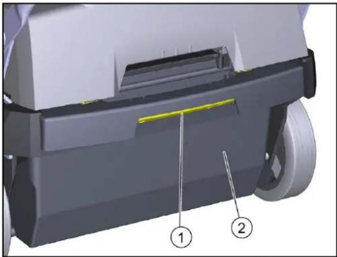
natural_image
3D mechanical component diagram showing a shaft and housing with labeled parts (1 and 2), no readable text or symbols beyond labels.① قفل حاوية الكناسة
② حاوية الكناسة
text_image
Diagram of a mechanical device with numbered components and labeled parts, including yellow circular elements and directional arrows.① يل/الإيقاف
② ضطى
③naة الدوارة
natural_image
3D mechanical component diagram showing a clamping mechanism with a red arrow indicating rotation (no text or symbols present)natural_image
Exterior view of a black industrial container with plastic wrap covering the interior (no text or symbols visible)5.أexistsGlqmshabkThiit
text_image
Technical diagram of a KAROLR cleaning machine with numbered components and control panel interfaceتجهيزات السلام
- LTD LED - LTD LED - LTD LED
natural_image
Black silhouette of a hand giving a thumbs-up gesture (no text or symbols)THANK YOU!
MERCI! DANKE! iGRACIAS!
Registrieren Sie Ihr Produkt und profitieren Sie von vielen Vorteilen. Register your product and benefit from many advantages. Enregistrez votre produit et bénéficier de nombreux avantages. Registre su producto y aproveche de muchas ventajas.
www.kaercher.com/welcome

Bewerten Sie Ihr Produkt und sagen Sie uns Ihre Meinung. Rate your product and tell us your opinion. Évaluer votre produit et dites-nous votre opinion. Reseñe su producto y díganos su opinión.

natural_image
Icon showing a gear and wrench, no text or symbols presentwww.kaercher.com/dealersearch
Alfred Kärcher SE & Co. KG
Alfred-Kärcher-Str. 28-40
71364 Winnenden (Germany)