
B 260 RI Bp - Industrial floor scrubber Kärcher - Free user manual and instructions
Find the device manual for free B 260 RI Bp Kärcher in PDF.
| Product type | Ride-on industrial scrubber dryer |
| Brand | Kärcher |
| Model | B 260 RI Bp |
| Dimensions (L × W × H) | 1925 × 1040 × 1565 mm (without roof) / 2560 × 1340 × 2200 mm (Combo with roof) |
| Operating weight (with batteries and full tanks) | 1641 to 1845 kg depending on version |
| Fresh water / waste water tank capacity | 260 L / 260 L |
| Battery | 36 V, 630 Ah, charging time 10 h |
| Working width | 1000 mm (R100), 1200 mm (R120) or 1000 mm (D100) |
| Max. travel speed | 10 km/h forward, 6 km/h reverse |
| Max. slope during operation | 15 % (RI versions) / 10 % (RI Combo versions) |
| Cleaning programs | Transport, Eco, Auto-wash, Scrubbing, Suction, Polishing |
| Suction power | Vacuum 14 kPa (140 mbar), air flow 28 L/s × 2 |
| Traction motor power | 2200 W |
| Suction motor power | 2 × 840 W |
| Brush motor power | 2 × 1100 W |
| Safety devices | Safety switch, seat switch, thermal protection, parking brake |
| Sound level | L_pA 73 dB(A), L_WA 94 dB(A) |
| Protection class | IPX3 |
Frequently Asked Questions - B 260 RI Bp Kärcher
User questions about B 260 RI Bp Kärcher
0 question about this device. Answer the ones you know or ask your own.
Ask a new question about this device
Download the instructions for your Industrial floor scrubber in PDF format for free! Find your manual B 260 RI Bp - Kärcher and take your electronic device back in hand. On this page are published all the documents necessary for the use of your device. B 260 RI Bp by Kärcher.
USER MANUAL B 260 RI Bp Kärcher
natural_image
Two industrial cleaning machines with yellow power lines and blue trim, no visible text or symbolsDeutsch 8
English 18
Français 28
Italiano 38
Español 49
Português 59
Nederlands 70
Türkçe 80
Svenska 90
Suomi 100
Norsk 109
Dansk 119
Eesti 129
Latviešu 138
Lietuviškai 148
Polski 158
Magyar 169
Čeština 179
Slovenčina 189
Slovenščina 199
Românește 209
Hrvatski 219
Srpski 229
Ελληνικά 239
Русский 250
Українська 262
Български 273
中文 284
한국어 293
日本語 302
العربيya 321
B 260 RI Bp Dose+SB+R100
B 260 RI Bp Pack Dose+SB+R100
B 260 RI Bp Dose+D100
B 260 RI Bp Pack Dose+D100
B 260 RI Bp Dose+SB+R120
B 260 RI Bp Pack Dose+SB+R120
B 260 RI Bp
B 260 RI Bp SB
B 260 RI Bp
B 260 RI Bp SB
B 260 RI Bp COMBO
B 260 RI Bp SSD
A


flowchart
graph TD
    A["1"] --> B["2"]
    B --> C["3"]
    C --> D["4"]
    D --> E["5"]
    E --> F["6"]
    F --> G["7"]
    G --> H["8"]
    style A fill:#FFD700,stroke:#333
    style B fill:#FFD700,stroke:#333
    style C fill:#FFD700,stroke:#333
    style D fill:#FFD700,stroke:#333
    style E fill:#FFD700,stroke:#333
    style F fill:#FFD700,stroke:#333
    style G fill:#FFD700,stroke:#333
    style H fill:#FFD700,stroke:#333
natural_image
Interior view of a car seat with numbered components (no visible text or symbols)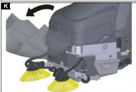
natural_image
Close-up of a cleaning or cleaning robotic device with yellow filter bands, showing mechanical components and a directional arrow (no text or symbols visible)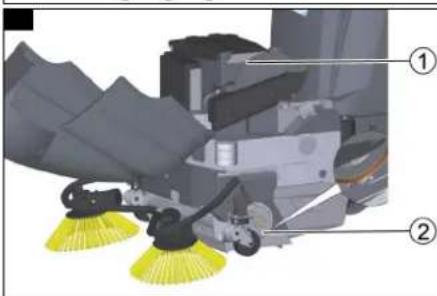
natural_image
Diagram of a cable or connector with directional arrows indicating motion or flow (no text or symbols)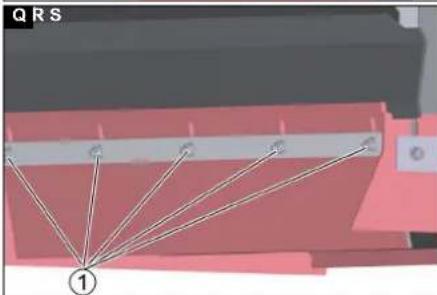
natural_image
Diagram showing a geometric structure with labeled points and lines, no readable text or symbols present.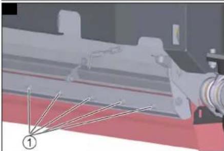
natural_image
Industrial machinery component with no visible text or symbols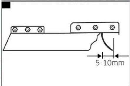
natural_image
Mechanical assembly diagram showing a wheel and mechanical components (no text or symbols visible)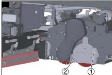
natural_image
Mechanical assembly diagram showing components labeled ① and ② (no readable text or symbols)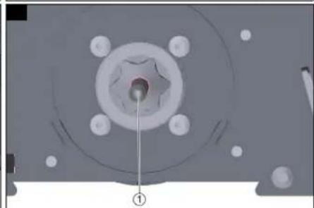
natural_image
Mechanical component with a central hub and mounting holes, labeled with number ① (no text or symbols on the main subject)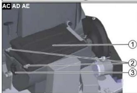
natural_image
Interior view of a vehicle or electronic device showing a panel with buttons and a labeled component (no readable text or symbols)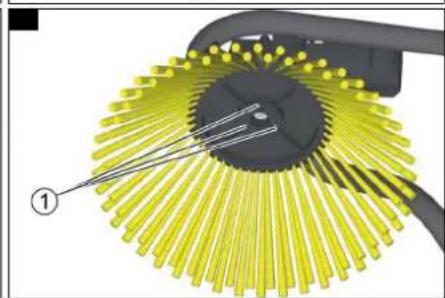
natural_image
Diagram of a mechanical component with yellow radial blades and a black handle, labeled with number ① (no text or symbols on the diagram itself)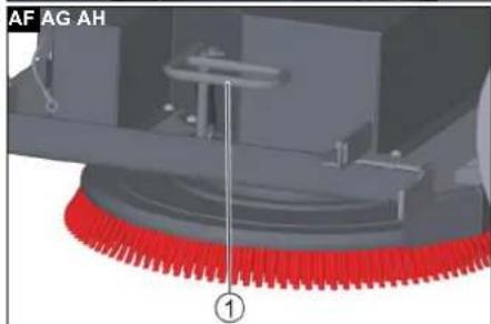
natural_image
Mechanical assembly diagram showing a motor, gear, and housing components (no text or symbols visible)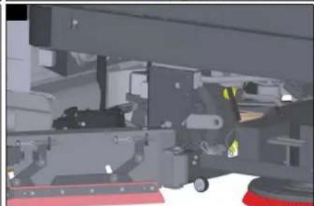
natural_image
3D mechanical assembly diagram showing a vehicle chassis with no visible text or symbols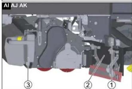
natural_image
Mechanical assembly diagram showing a vehicle wheel and attached components (no visible text or symbols)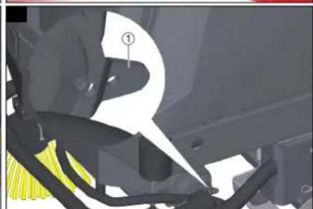
natural_image
Mechanical assembly diagram showing a component with highlighted parts and numbered annotation (no readable text or symbols)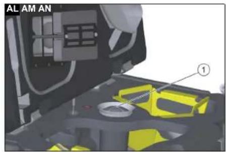
natural_image
Mechanical assembly diagram showing a red-handled wheel and mechanical components (no text or symbols visible)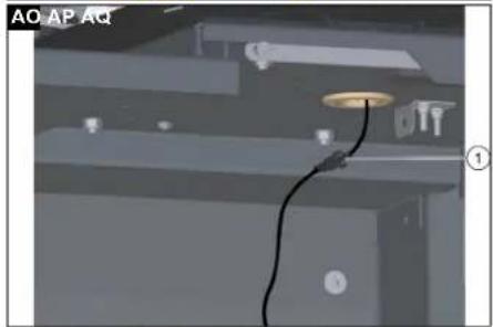
natural_image
Interior view of a room with ceiling-mounted fixtures and a cable, no visible text or symbols
natural_image
3D mechanical assembly diagram showing internal components and a labeled section (①), no readable text or symbols present.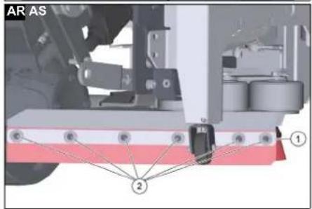
Inhalt
71364 Winnenden (Germany)
Tel.: +49 7195 14-0
Fax: +49 7195 14-2212
Winnenden, 2021/03/01
Contents
General notes 18
Function 18
Intended use 18
Environmental protection 18
Warranty.... 18
Accessories and spare parts.... 18
Scope of delivery 18
Safety instructions.... 18
Description of the device.... 19
Installation.... 19
Operation 20
Finishing operation.... 22
Grey Intelligent Key 22
Yellow Intelligent Key 23
White intelligent key 23
Transport....23
Storage 23
Care and maintenance.... 23
Troubleshooting guide.... 25
Technical data.... 26
EU Declaration of Conformity 28
General notes
Read these original operating instructions and the enclosed safety instructions before using the device for the first time. Proceed accordingly.
Keep both books for future reference or for future owners.
Function
This scouring and vacuum machine is used for wet cleaning or polishing of level floors.
With the Combo variant, loose dirt is picked up by a sweeping mechanism before cleaning.
The device can be adjusted to suit the respective cleaning task by adjusting the water quantity, contact pressure, brush speed, detergent volume and travel speed. A working width of 1000mm or 1200mm and a capacity of 260 l in the fresh and waste water tank each enable effective cleaning with long working times.
The device has a travel drive, the driving motor is powered by a traction battery. The batteries can be charged by means of a charger at a 230-V socket.
Battery and charger are already supplied with the package variants.
Note
The device can be equipped with various accessories to suit the respective cleaning task. Request a copy of our catalogue or visit our Internet website at www.kaercher.com.
Intended use
This device is suitable for commercial and industrial use, e.g. logistics halls, factories, industrial systems, car parks, trade fairs and retail premises. Use this device only in accordance with the information in these operating instructions.
- The device may only be used for cleaning floors that are insensitive to water and polishing.
- The device is designed for cleaning indoor floors or covered areas. For other application areas, the use of alternative brushes or the use of the sweeping mechanism must be checked.
- The operational temperature range is between +5 °C and +40 °C.
- The device is not suitable for cleaning frozen floors (e.g. in cold stores).
- With the Combo variant: The device may be driven over steps up to a maximum height of 2 cm.
- The device may not be operated without a lint filter in the waste water tank.
- The device is not intended for cleaning public traffic routes.
- The device must not be used on pressure-sensitive floors. Take into account the permissible load per unit area of the floor. The area load imposed by the device is specified in the Technical data.
- The device may only be fitted with original accessories and spare parts.
- The device is not suitable for use in potentially explosive environments.
- No flammable gases, undiluted acids or solvents may be taken up with the device. These include petrol, paint thinner or heating oil, which can form explosive mixtures in the suction air turbulence. Do not use acetone, undiluted acids or solvents, as these corrode the materials used on the device.
Environmental protection

The packing materials can be recycled. Please dispose of packaging in accordance with the environmental regulations.

Electrical and electronic devices contain valuable, recyclable materials and often components such as batteries, rechargeable batteries or oil,
which - if handled or disposed of incorrectly - can pose a potential danger to human health and the environment. However, these components are required for the correct operation of the device. Devices marked by this symbol are not allowed to be disposed of together with the household rubbish.
Notes on the content materials (REACH)
Current information on content materials can be found at: www.kaercher.de/REACH
Warranty
The warranty conditions issued by our sales company responsible apply in all countries. We shall remedy possible malfunctions on your device within the warranty period free of cost, provided that a material or manufacturing defect is the cause. In a warranty case, please contact your dealer (with the purchase receipt) or the next authorised customer service site.
(See overleaf for the address)
Accessories and spare parts
Only use original accessories and original spare parts. They ensure that the appliance will run fault-free and safely.
Information on accessories and spare parts can be found at www.kaercher.com.
Scope of delivery
Check the contents for completeness when unpacking. If any accessories are missing or in the event of any shipping damage, please notify your dealer.
Safety instructions
Before using the device for the first time, read and observe these operating instructions and the accompanying brochure: Safety instructions for brush cleaning devices, No. 5.956-251.0.
The device is approved for operation on surfaces with a specified limited slope (see chapter "Technical Data").
△WARNING
The device can tip over
Risk of injury
Only operate the device on surfaces that do not exceed the permitted slope (see chapter "Technical Data").
△WARNING
Risk of accident due to incorrect operation
People can be injured.
Operators must be properly trained on how to use this machine.
The device may only be operated when the hood and all covers are closed.
Safety devices
△CAUTION
Missing or modified safety devices!
Safety devices are provided for your own protection.
Do not bypass, remove or render ineffective any safety devices.
Safety switch
For immediate shutdown of all functions: Set the safety switch to "0".
- The device brakes hard when the safety switch is switched off.
- The safety switch acts directly on all device functions
Seat switch
If the operator leaves the seat during work or while driving, the seat switch switches off the engine after a short delay.
Warning symbols
Observe the following warnings when handling the batteries:
| Observe notes in the instructions for the battery, on the battery and in these operating instructions. | |
| Wear eye protection. | |
| Keep acids and battery away from children. | |
| Risk of explosion | |
| Fire, sparks, open flames and smoking are prohibited. | |
| Risk of acid burns | |
| First aid. | |
| Warning | |
| Disposal | |
| Do not dispose of used batteries in the residual waste. |
△DANGER
Danger due to explosion
Risk of injury and damage
Do not place any tools or objects on the battery, i.e. on the end poles and cell connectors.
△DANGER
Risk of injury!
Ensure that wounds never come into contact with lead.
Always clean your hands after working on batteries.
Symbols on the charger

△DANGER
Risk of fire
If plugged into an unsuitable socket or in the event of poor electrical connection between the plug and the socket, the charger plug and the socket used may get very hot.
Before plugging in the mains plug, make sure that the socket is approved for a current of 16 A and that it is in a technically sound condition.
Make sure that the mains plug is clean and in a good condition.
△CAUTION
Do not operate the device together with other devices on an extension cable with multiple power sockets.
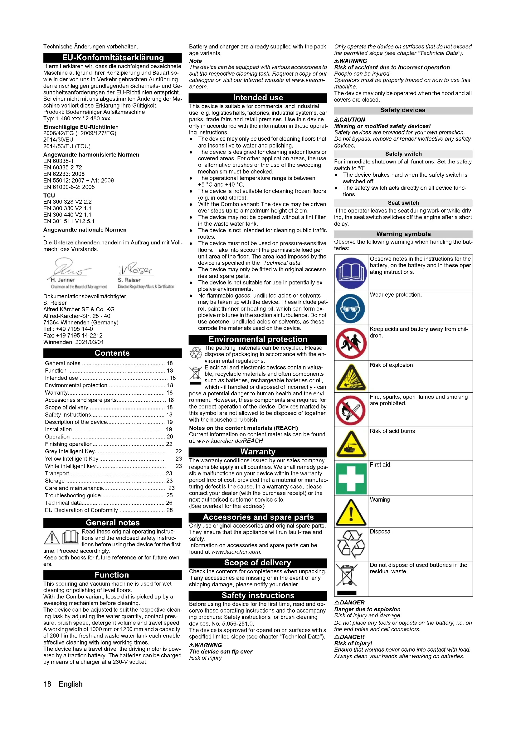
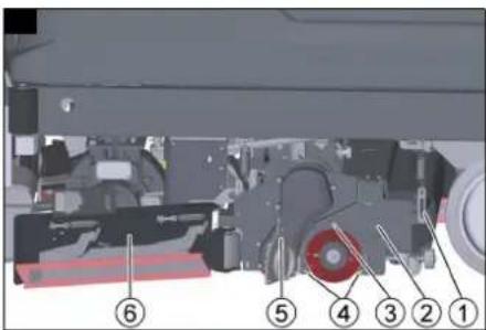
Description of the device
Device overview, front
Illustration B
① Steering wheel
② Fresh water tank automatic filling system
③ pre-sweeping unit hood***
④ Side brushes*
⑤Driving motor
⑥ Squeegee blade holder
⑦ Squeegee blade
⑧ Suction bar
* Optional *** Combo variant only
Device overview, rear
Illustration A
① Overhead guard*
②Flashing beacon*
③Blue spotlight rear/ front*
④ Suction lance for DOSE detergent dosing unit*
⑤ Waste water tank cap
⑥ Fresh water drain hose
⑦ Waste water drain hose
⑧ Manual tank cleaning - spray gun
⑨ Suction hose
⑩ Suction beam ram protection*
⑪ Waste water tank inspection opening
⑫ Waste container***
13 Fresh water lid
14 Control panel
* Optional *** Combo variant only
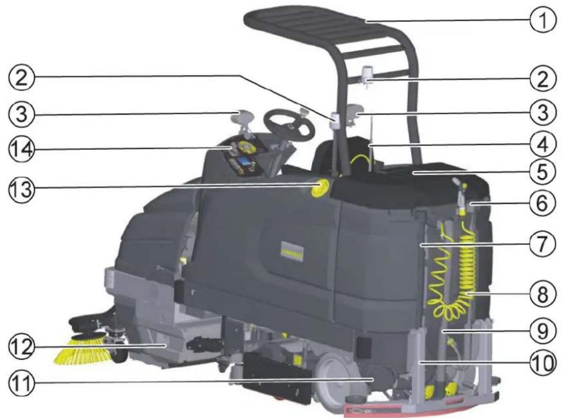
Device overview, seat
Illustration C
①Detergent tray for DOSE detergent dosing unit*
2 Seat
③Steering wheel knob
④ Weight adjustment lever
⑤ Seat length adjustment lever
* Optional
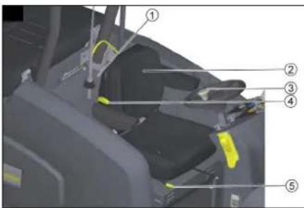
Device overview, waste water tank
Illustration D
① Waste water tank support
②Float
③ Waste water impact protection
④ Waste water tank cap
⑤Coarse dirt basket
⑥ Turbine pre-filter
⑦ Waste water tank
Device overview, pedals
Illustration AP
①Coarse dirt flap pedal
② Brake pedal
③ Accelerator pedal
Device overview, pre-sweeping unit
Illustration E
①Filter housing cover
② pre-sweeping unit hood***
③Side brushes***
④Filter housing
⑤ Sweep container
*** Combo variant only
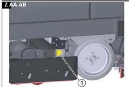
Type plate
Illustration AJ
①Type plate
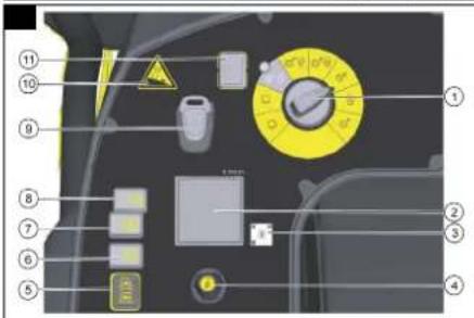
Control panel
Illustration F
①Program switch
②Display
③QR code for the how-to video
④Info button for menu navigation in the display
⑤Driving direction switch
⑥2-stage horn
⑦Cleaning solution ON/OFF
⑧Side brush/side scrubbing deck ON/OFF (side brush option with Combo variant)
⑨ Intelligent key
⑩ Maximum permissible gradient
⑪ Safety switch
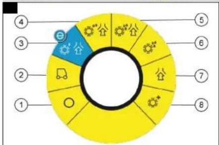
Program switch
Illustration G
①0
Device is switched off.
②Transport journey
Drive to the operating location.
③Eco program
Clean the floor wet (with a reduced water quantity and a reduced brush speed) and vacuum up waste water (with reduced suction power).
④ Scour and vacuum
Clean the floor wet and vacuum up waste water.
⑤ Increased brush contact pressure
Clean the floor wet (with increased brush contact pressure and increased water quantity) and vacuum up the waste water.
⑥ Scouring / pre-cleaning without vacuuming
Clean the floor wet and let the detergent act.
⑦Vacuuming
Vacuum up the dirty liquid.
⑧Polishing
Polish the floor at a high brush speed without applying liquid.
Symbols on the device

Drain for fresh water

Drain for waste water

Fresh water

Fresh water tank automatic filling system

Removing the coarse dirt basket

Lashing point
* Optional
Pictograms on the display
Battery full

Battery empty

Brake activated

Preliminary sweep work activated

Water off

Detergent activated

Detergent empty

Fresh water 100%

Fresh water 0%
Installation
Batteries
Recommended batteries, chargers
| Order no. | |
| Battery set 2.815-108.0 | |
| Charger 4.035-191.0 | |
| Volume (m3)* 71.78 | |
| Airflow (m3/h)** 27.71 |
* Minimum volume of the battery charging room
** Minimum airflow between battery charging room and environment
Batteries and chargers are available from specialist shops.
Maximum battery dimensions
| Length Width Height | |
| 842 627 mm 537 mm |
The following must be observed when fitting the wet batteries:
- The maximum battery dimensions must be observed.
- The seat must be pivoted up when charging wet batteries.
- The battery manufacturer's regulations must be observed when charging wet batteries.
Fitting and connecting batteries
The batteries are already installed in the Bp variant. If you did not receive a Bp variant, the batteries were retrofitted at the national company or at your trusted dealer. This may be for availability, time, cost, import, service, transport or similar reasons to your advantage.
ATTENTION
Risk of damage to the control electronics!
The control electronics can be destroyed by reversing the polarity of the battery connections.
Take care to ensure the correct polarity when connecting the batteries.
-
Adjust the steering wheel position all the way forward.
-
Pivot the seat forward.
- Remove the seat stop screw.
- Remove the plug of the seat contact switch and push it back through the opening. Illustration AO
① Seat contact switch plug
-
Unlock the seat and pull it upwards.
-
Remove the seat contact switch plug from the holder.
-
Unhook the support for the seat console and close the seat console.
-
Unscrew the hinges of the seat console.
-
Place the seat console in the footwell.
-
Only with Dose variant: Remove the detergent canister tray.
-
Only with Fleet variant: Remove the cables.
-
Lift off the battery cover.
-
Remove the fresh water tank on the right.
-
Remove the battery box side panel on the right.
-
Fit the battery. Battery terminals positioned at the front in the travel direction.
-
Clamp the supplied power cables to the (+) and (-) battery terminals that are still free. Route the cable so that it cannot be pinched by the seat.
-
Only with Fleet variant: Install the cables.
-
Install the battery box side panel on the right.
-
Install the fresh water tank on the right.
-
Fit the battery cover.
-
Insert the battery plug.
-
Fit the seat console.
-
Screw on the hinges of the seat console.
-
Open the seat console and hook in the seat console support.
-
Install the seat contact switch plug on the holder.
-
Fit the seat.
-
Plug in the seat contact switch plug.
-
Install the seat stop screw.
-
Pivot the seat downwards.
-
Adjust the steering wheel.
△WARNING
Danger to life from fire or explosion if batteries are deeply discharged!
Incorrect charging of deeply discharged batteries can cause a fire.
Do not start the device if the battery is deeply dis-
charged.
Make sure that the battery is charged before starting the system.
Charging the battery
Note
The device has deep discharge protection, i.e. the device can only be driven when the permitted minimum capacity level is reached. "Battery empty - please charge" appears in the display.
When using other batteries (e.g. from other manufacturers), the deep discharge protection for the respective battery must be reset by Kärcher Customer Service.
△DANGER
Danger of death from electric shock!
There is a danger of electrical shock if the charger is used improperly
Adhere to the mains voltage and fuse values specified on the device type plate.
Only use the charger in dry rooms with sufficient ventilation.
Danger of explosion when charging the battery! Flammable gases are generated when the battery is charged
Only charge the batteries in a suitable room. The room must have a minimum volume depending on the battery type and an adequate air exchange rate with a minimum air flow (see "Recommended batteries").
Only charge wet batteries with the seat pivoted up.
Note
The average charging time is approx. 10-12 hours hours.
The recommended chargers (for the respective batteries) are electronically controlled and end the charging process automatically.
The device cannot be used during the charging process.
- Drive the device directly to the charger and do not drive on slopes.
- Pivot the seat upwards.
- Disconnect the battery plug and connect it to the charging cable.
- Connect the charger to the mains and switch it on.
After the charging process
- Switch off the charger and disconnect it from the mains.
- Disconnect the battery cable from the charging cable and connect it to the device.
Note
Route the charging cable in the battery compartment so that it cannot be pinched.
Low-maintenance batteries (wet batteries)
△DANGER
Refilling discharged batteries with water
Danger of acid burns from escaping acid, destruction of clothing
Wear safety goggles, protective clothing and protective gloves when handling the battery acid. Observe the applicable regulations.
Immediately rinse off any splashed acid from the skin or clothing using copious amounts of water.
ATTENTION
Using water with additives
Defective batteries, loss of warranty eligibility
Top up the batteries using only distilled or desalinated water (EN 50272-T3).
Do not use any foreign additives, so-called enhancing agents, because this will invalidate the warranty.
-
Add distilled water one hour before the charging process comes to an end. Observe the correct acid level according to the battery label. All cells must produce gas at the end of the charging process.
-
Clean up any spilled water. To do this, proceed as described in the Care and maintenance chapter in the "Cleaning the batteries" section.
Battery Indicator
The charging state of the batteries is shown on the control panel display.
- The length of the bar shows the battery charge state.
Unpacking
Note
Set the safety switch to the "0" position to shut down all functions immediately.
- Remove the packaging film.
- Remove the strap.
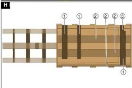
- Unscrew the unloading planks and squared timber from the pallet.
Illustration H
① Squared timber
②Unloading plank
③Block
- Place the squared timber in front of the pallet.
- Place the unloading plank on the squared timber.
- Screw on the unloading plank.
- Push the block provided in the packaging under the ramp to provide support.
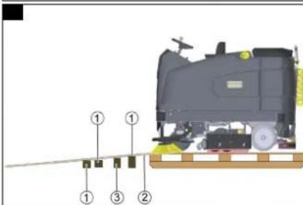
- Remove the wooden strips in front of the wheels. Illustration I
① Squared timber
②Unloading plank
③Block
- Push the device forwards off the pallet.
Pushing the device off the pallet
Note
Install the suction bar only after unloading.
- Release the parking brake via the lever (see chapter Pushing the device).
- One person must sit on the seat and press the brake pedal in the case of danger during pushing.
- Push the device down the ramp and off the pallet.
- Close the parking brake with the lever.
Driving off the pallet
The batteries must be installed and charged in order to drive off the pallet.
Note
Install the suction bar only after unloading.
- Insert the Intelligent Key into the control panel.
- Switch on the device using the Easy-Operation switch.
- Set the program switch to transport travel.
- Set the travel direction switch to "Forward".
- Depress the accelerator pedal.
- Drive the device slowly off the pallet.
- Switch off the device using the Easy-Operation switch.
Installing he brushes
BD Variant
The disc brushes must be installed before start-up (see chapter Maintenance work).
BR variant
The brushes are installed.
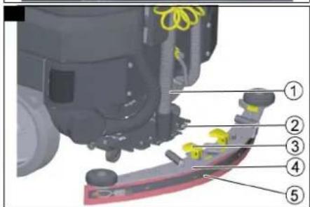
Installing the suction bar
- Pivot both clamping levers upwards. Illustration M
① Suction hose
② Suction bar suspension
③ Clamping lever
④ Suction bar
⑤ Suction lip with strap
2. Fit the suction bar in the suction bar mount.
3. Pivot both clamping levers downwards.
Operation
△DANGER
Falling objects
Risk of injury
Do not used the device without an overhead guard to protect against falling objects in areas in which there is a possibility of operators being hit by falling objects.
ATTENTION
Risks during operation
Risk of injury
In the event of danger, set the safety switch to "0".
Switching the device on
- Sit in the driver's seat.
- Insert the Intelligent Key.
- Set the safety switch to "1".
- Turn the program switch to the desired function.
- If one of the displays below appears on the display, take your foot off the accelerator pedal, set the safety switch to "0" and carry out the necessary maintenance work.
| Display Activity | |
| Suction bar maintenance | Clean the suction bar. |
| Brush head maintenance | Check the brushes for wear and clean them. |
| Suction lip maintenance | Check the suction lips for wear and correct adjustment. |
| Turbine sieve maintenance | Clean the turbine screen. |
| Maintenance of the fresh water filter | Clean the fresh water filter. |
-
Press the Info button.
-
Reset the counter for the corresponding maintenance (see "Grey Intelligent Key / Reset maintenance counter").
Note
If the counter is not reset, the maintenance display appears again each time the device is switched on.
Checking the parking brake
△DANGER
Danger of death due to defective parking brake!
The device may roll uncontrollably if the parking brake is not working properly.
Check the function of the parking brake on level ground before each use.
- Switch the device on.
- Set the travel direction switch to "Forward".
- Set the program switch to transport travel.
-
Press the accelerator pedal lightly.
The brake must audibly unlock. The device must roll easily on level ground. -
Release the accelerator pedal.
The brake must audibly lock.
If the parking brake does not lock, shut down the device, secure it against uncontrolled rolling and contact the customer service.
Checking the foot brake
△DANGER
Danger of accident due to defective foot brake!
The device may roll uncontrollably if the foot brake is not working properly.
Check the function of the parking brake on level ground before each use.
-
Switch the device on.
-
Set the travel direction switch to "Forward".
-
Set the program switch to transport travel.
-
Press the accelerator pedal.
-
While driving, take your foot off the accelerator and apply the foot brake.
Device must decelerate noticeably.
If this is not the case, shut down the device and call Customer Service.
Driving
△DANGER
Lack of braking
Danger of accident
Before using the device, it is essential to check the function of the parking brake. Never use the device if the parking brake does not work.
△DANGER
No braking effect during operation
If the device no longer has any braking effect during operation, proceed as follows:
If the device does not come to a standstill on a ramp with a gradient of more than 2% when you release the accelerator pedal, for safety reasons you may only set the safety switch to position "0" if you have checked the correct mechanical function of the parking brake before starting up the device.
After reaching a standstill, put the device out of operation and call Customer Service.
Observe the maintenance instructions for brakes.
△DANGER
Careless driving
Danger of tipping over
Only drive on slopes in the travel direction up to a maximum of 15% (RI variant) and 10% (RI Combo variant). Slopes transverse to the travel direction up to a maximum of 15%.
Do not turn up or down gradients.
Drive slowly in corners and on wet ground.
Only drive the device on stable ground.
Pivoting sweeping mechanism on the Combo variant
Increased risk of accidents
Be especially careful when reversing.
Take the pivoting of the sweeping mechanism into account when steering.
Note
The travel direction can be changed while driving. This allows very dull spots to be polished by moving back and forth several times.
-
Assume a seated position.
-
Insert the Intelligent Key.
-
Set the program selection switch to "Transport travel".
-
Set the travel direction using the travel direction button on the control panel.
-
Specify the travel speed by pressing the accelerator pedal.
-
Release the accelerator pedal. The device stops.
The driving motor is switched off in the event of an overload. A fault message appears on the display. If the controller overheats, the affected power unit is switched off.
-
Allow the device to cool down for at least 15 minutes.
-
Set the program switch to "0", wait briefly and set to the desired program.
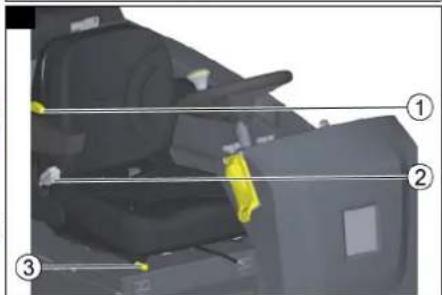
Adjusting the driver's seat
Illustration J
①3-stage weight adjustment 60-120 Kg
② Backrest tilt adjustment 3° forward and 13° backward
③ Seat length adjustment
-
Operate the seat adjustment lever.
-
Move the seat to the desired position.
-
Release the seat adjustment lever.
Adjusting the steering wheel
-
Release the wing nuts for adjusting the steering wheel.
-
Position the steering wheel.
-
Tighten the wing nuts.
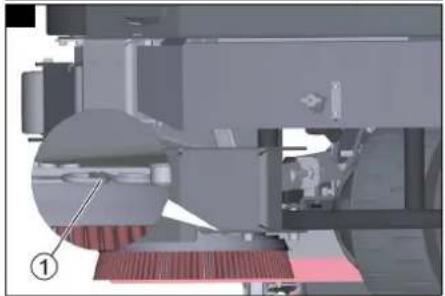
Checking the lint filter
ATTENTION
Damage to the suction turbine!
Operating without a lint filter can damage the suction turbine.
Do not operate the device without the lint filter.
- Check the following lint filter aspects before starting up the device:
Is it present?
- Is it in a usable condition?
- Is it installed correctly?
Illustration AL
①Lint filter
- Replace a damaged lint filter.
Pushing the device
- Release the parking brake by pulling the lever away.
Note
The lever must be pulled all the way.
△DANGER
Risk of injury from rolling device!
The parking brake can only be released while bent over and staying in the danger zone.
Use an object to hold the lever in a permanently pulled state and move away from the danger zone immediately after opening the parking brake.
Illustration AK
①Parking brake lever
-
Push the device.
-
Close the parking brake again by releasing the lever.
Filling with fresh water
Filling fresh water
-
Open the fresh water tank cap
-
Secure the fresh water hose with the clamp.
-
Fill fresh water (max. 60 °C) to approx. 5 cm below the filler funnel.
Note
Fill the fresh water tank completely before initial startup in order to vent the water pipe system.
- 'Remove the fresh water tank cap
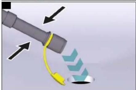
Filling fresh water with the fresh water tank automatic filling system (option)
Note
We recommend that you use a hose with an Aquastop coupling on the device side. This minimises the splashing out of water when disconnecting after the filling process.
-
Connect the water hose to the automatic filling system.
-
Open the water supply (max. 60 °C, max. 10 bar).
-
Monitor the filling process, the automatic filling system interrupts the water supply when the fresh water tank is full.
-
Close the water inlet.
-
Remove the water hose.
Filling with detergent
Notes on detergents
△WARNING
Unsuitable detergents
Health risk, damage to the device
Use only recommended detergents. The operator carries all increased risks relating to operational safety and increased risk of accidents if using other detergents. Use only detergents free of solvents, salt and hydrofluoric acid.
Adhere to the safety instructions stated on the detergent packaging.
Note
Do not use heavily foaming detergent.
Recommended detergents
| Application Detergent | |
| Maintenance cleaning of all water-resistant floors | CA 50 CRM 756 |
| Maintenance cleaning with care components | RM 746RM 780 |
| Maintenance cleaning and basic cleaning of industrial floors | RM 69 |
| Maintenance cleaning of glossy coverings | RM 755 |
| Application Detergent | |
| Maintenance cleaning and basic cleaning of fine stone tiles | RM 753 |
| Maintenance cleaning and basic cleaning of acid-resistant coverings | RM 751 |
| Cleaning and disinfection RM 732 | |
| Basic cleaning of all alkali-resistant floor coverings | RM 752 |
| Basic cleaning and de-coating of alkali-sensitive floors | RM 754 |
Filling the detergent into the fresh water tank
Note
First fill water into the detergent tank, then add the appropriate dosage of detergent to the tank. If the detergent is poured in first, this can lead to strong foaming.
ATTENTION
Danger of clogging
When adding detergent to the fresh water tank, the detergent can dry out and disrupt the function of the dosing device.
Rinse the device with clear water after adding the detergent to the fresh water tank: Select a cleaning program with water application, set the water quantity to the highest value, set the detergent dosage to "0".
Filling detergent with a dosing device
(option)
Detergent is added to the fresh water on the way to the cleaning head by a dosing device.
Note
A maximum of 3% detergent can be added with the dosing device. If the dosage is higher, the detergent must be added to the fresh water tank.
ATTENTION
Danger of clogging
When adding detergent to the fresh water tank, the detergent can dry out and disrupt the function of the dosing device.
Rinse the device with clear water after adding the detergent to the fresh water tank: Select a cleaning program with water application, set the water quantity to the highest value, set the detergent dosage to 0.
Place the canister with the detergent in the detergent tray behind the seat.
-
Unscrew the canister cap.
-
Insert the detergent suction lance of the dosing device into the canister.
Note
The device has a fresh water level indicator on the display. Detergent dosing is also stopped when the fresh water tank is empty. The cleaning head continues to work without supply of liquid.
Detergent addition is also stopped when the detergent canister is empty. A message symbol appears on the display. Only fresh water is fed to the cleaning head.
Adjusting parameters (yellow Intelligent key)
The parameters for the various cleaning programs are preset in the device.
Individual parameters can be changed depending on the authorization of the yellow Intelligent Key.
The modified parameters only remain in effect until a different cleaning program is selected with the program switch.
A grey Intelligent Key must be used for making adjustments if parameters are to be changed permanently.
This setting procedure is described in the section "Grey Intelligent Key".
Note
R cleaning head only: Almost all displayed texts regarding parameter settings are self-explanatory. If you need more detailed information about the parameters, please contact the Customer Service.
Fine Clean: Low brush speed for removing grey film from fine stone.
Whisper Clean: Medium brush speed for maintenance cleaning with reduced noise level.
Power Clean: High brush speed for polishing, crystallizing and sweeping.
Set the program switch to the desired cleaning program.
Press the Info button.
Turn the Info button until the desired parameter is displayed.
Press the Info button.
The adjusted value flashes.
Set the desired value by turning the Info button.
Confirm the changed setting by pressing the Info button or wait until the set value is automatically accepted after 10 seconds.
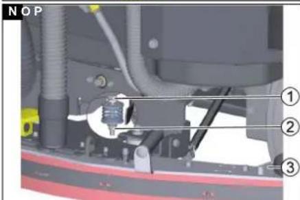
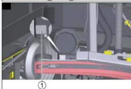
Adjusting the suction bar
The suction bar only needs to be readjusted in special cases. The factory setting is suitable for most applications.
Adjusting the inclination of the suction bar
The inclination must be adjusted so that the suction lips of the suction bar make even contact with the floor over the entire length of the suction bar.
-
Park the device on a surface without a slope.
-
Select the "Suction" program.
-
Drive the device a small distance forwards. The suction bar is lowered.
-
Read the spirit level.
Illustration N
① Screw
②Nut
③ Spirit level
-
Release the M 12 nut while holding the M 10 hexagon head screw with an open-end wrench.
-
Adjust the screw so that the spirit level indicator is between the two lines.
-
Tighten the M 12 nut while holding the M 10 hexagon head screw with an open-end wrench.
-
To check the new setting, move the device forward a short distance in suction mode with the suction bar lowered and observe the spirit level. Repeat the adjustment process if necessary.
Sweeping (Combo variant only)
The sweeping mechanism picks up loose dirt before cleaning the floor.
△WARNING
Moving parts
Risk of injury
Note that the suction turbine, side brushes and filter dedusting run on after switching off.
ATTENTION
Improper use of the device when sweeping
Risk of damage to the sweeping mechanism. Do not sweep up packing tape, wires or similar.
Only drive over steps up to a maximum of 2 cm. Sweep only dry surfaces to prevent clogging and contamination of the dust filter.
- Switch on the "Sweeping" switch. The sweeping mechanism is activated.
Coarse dirt flap
The coarse dirt flap can be lifted to sweep up larger objects (up to approx. 6 cm high).
△DANGER
Risk of injury from waste!
Waste can be thrown out when the coarse dirt flap is opened.
Only lift the coarse dirt flap when there are no persons in the vicinity.
Note
The sweeping effect and dust suction deteriorate when the coarse dirt flap is raised. Only lift the coarse dirt flap when necessary.
- Operate the pedal to raise the coarse dirt flap.
Ending sweeping
- Set the "Sweeping" switch to "0".
The sweeping mechanism is deactivated. After the sweeping operation is finished, the dust filter is cleaned for approx. 15 seconds.
Side scrubbing deck (option)
The side scrubbing deck makes working close to the
edge easier
Illustration AS
① Extending/retracting the side scrubbing deck
② Switching the side scrubbing deck on/off
- Press the "Switch side scrubbing deck on/off" switch.
The side scrubbing deck is switched on/off.
- Press the "Retract/extend side scrubbing deck" switch.
The side scrubbing deck is retracted/extended.
Finishing operation
Finishing cleaning
-
Set the program selection switch to Drive.
-
Continue moving a short distance.
The residual water is vacuumed up.
-
Turn the program selection switch to position "0".
-
Remove the Intelligent Key.
-
Charge the battery if necessary.
Emptying the waste water tank
△WARNING
Improper disposal of waste water Environmental pollution
Observe the local waste water treatment regulations.
Note
The suction turbine switches off and the display shows "Waste water tank full" when the waste water tank is full.
-
Remove the waste water drain hose from the holder.
-
Lower the end of the hose over the disposal facility. Illustration P
-
Drain the waste water by opening the cap on the drain hose. The water flow can be reduced by squeezing or twisting the dosing device.
-
Remove the spray gun from the holder.
-
Set the program selection switch to Transport.
-
Select "Tank rinsing" on the display. a Press the Info button.
b Select the "Tank rinsing" menu.
-
Open the stop valve on the back of the waste water tank.
-
Rinse the waste water tank with the spray nozzle.
-
Hang the spray nozzle in the holder.
-
Close the drain hose cover
-
Press the waste water hose into the support on the device.
-
Close the stop valve at the back of the waste water tank.
-
Select "Tank rinsing" on the display.
Emptying the waste container
Note
The waste container can only be removed via the driver's side and is only present on R cleaning heads.
-
Pull the tab.
-
Pivot open the squeegee blade holder.
-
Remove the waste container.
Illustration AI
①Tab
② Squeegee blade holder
③ Waste container
-
Empty the waste containers.
-
Fit the waste container.
Note
The waste container must latch into place.
- Pivot the squeegee blade holder closed.
Draining fresh water
ATTENTION
Cleaning solution in the fresh water tank
Damage to fresh water tank, valves and seals Never leave the cleaning solution in the fresh water tank at the end of operation.
-
Remove the fresh water drain hose from the holder and lower it over a suitable collecting device.
-
Drain the cleaning solution.
-
Remove the fresh water tank cap
-
Rinse the fresh water tank with clear water (maximum 60 °C).
Shutting down the device
-
Turn the key-operated switch to "OFF".
-
Remove the Intelligent Key.
-
Secure the device against rolling away.
-
Charge the battery if necessary.
Grey Intelligent Key
The grey Intelligent Key grants the supervisory staff extended authorizations and setting options.
-
Insert the Intelligent Key
-
Select the desired function by turning the info button.
Transport journey
-
Set the program selector switch to "Transport travel".
-
Press the Info button.
The following settings can be made in the Transport travel menu:
- Resetting the maintenance counter
- Resetting the day counter
• Key management
- Choosing the brush shape
• After-running time
- Standard setting
- Setting the language
- Switch menu
- Travel speed
- Factory setting
- Activating the manual tank rinsing gun
Resetting the maintenance counter
If maintenance work shown in the display has been carried out, the corresponding maintenance counter must then be reset.
-
Turn the Info button until "Maintenance counter" is displayed.
-
Press the Info button.
The counter readings are displayed.
-
Turn the info button until the counter to be cleared is highlighted.
-
Press the Info button.
-
Select "Yes" by turning the Info button.
-
Press the Info button.
The counter is cleared.
Note
The service counter can only be reset by Customer Service staff.
The service counter shows the time until the next service due by Customer Service.
Resetting the counter
- Turn the Info button until "Counter" is displayed. This menu shows the total operating hours and the day counter.
Delete the day counter:
- Press the Info button.
The "Delete counter" menu is displayed.
-
Turn the Info button until "Day counter" is highlighted.
-
Press the Info button.
Key management
The authorizations are assigned for each yellow Intelligent Key used and the language of the display is set for this Intelligent Key in the "Key menu" menu item.
-
Insert the grey Intelligent Key.
-
Turn the info button until the "Key menu" menu item appears on the display.
-
Press the Info button.
-
Remove the grey Intelligent Key and insert the yellow or white Intelligent Key to be personalized.
-
Select the menu item to be changed by turning the info button.
-
Press the Info button.
-
Select the setting of the menu item by turning the info button.
-
Confirm the setting by pressing the menu item.
-
Select the next menu item to be changed by turning the info button.
-
After all settings have been made, call up the "Save?" menu by turning the info button.
-
Press the Info button.
The authorizations are saved.
The "Continue key menu" display appears.
• Yes: Program another Intelligent Key
• No: Exit the key menu
- Press the Info button.
Choosing the brush shape
This function is required when changing the cleaning head.
-
Turn the info button until the "Brush head" menu item appears on the display.
-
Press the Info button.
-
Turn the info button until the desired brush shape is highlighted.
-
Press the Info button.
-
To change the cleaning head, move the lifting drive by turning the info button:
- "Up": Lifting
- "Down": Lowering
- "OFF": Stopping
-
Turn the info button until the "OFF" menu item is displayed.
-
Press the Info button.
The menu is exited.
The controller performs a restart.
After-running time
-
Turn the info button until the "After-running time" menu item appears on the display.
-
Press the Info button.
-
Turn the info button until the desired function is highlighted.
-
Press the Info button.
-
Turn the info button until the desired after-running time is displayed.
-
Press the Info button.
Standard setting
-
Turn the info button until the "Standard setting" menu item appears on the display.
-
Press the Info button.
-
Turn the info button until the desired accessory is highlighted.
-
Press the info button to confirm ON/OFF.
-
Press the info button to exit the menu.
-
Switch the device off and on again to adopt the setting.
Setting the language
- Turn the info button until the "Language" menu item appears on the display.
- Press the Info button.
- Turn the info button until the desired language is highlighted.
- Press the Info button.
Switch menu
The following functions are switched on and off via the "Switch menu":
- Detergent dosing*
- Flashing beacon/ spotlight*
- Side brush spray nozzles*
- Spray suction
- Work lights
- Tank rinsing
The "Switch menu" is available in all program switch positions, except "OFF".
- Press the Info button.
The "Switch menu" is displayed.
- Press the Info button
The list of functions available in the device is displayed.
-
Turn the info button until the desired function is highlighted.
-
Press the info button to change the switch state.
-
Turn the Info button until "Exit menu?" is displayed.
-
Press the Info button.
* Optional
Set maximum travel speed
-
Turn the info button until the "Travel speed" menu item appears on the display.
-
Press the Info button.
-
Turn the info button until the desired maximum speed is highlighted.
-
Press the Info button.
Factory setting
The factory settings of all parameters are restored (except transport travel speed).
-
Turn the info button until the "Factory setting" menu item is displayed.
-
Press the Info button.
-
Turn the Info button until "Yes" is highlighted.
-
Press the Info button.
Adjusting parameters for cleaning programs
All cleaning program parameters are retained until another setting is selected or the device is switched off.
-
Set the program switch to the desired cleaning program.
-
Press the Info button.
The first adjustable parameter is displayed.
- Press the Info button
The adjusted value flashes
-
Set the desired value by turning the Info button
-
Confirm the changed setting by pressing the Info button or wait until the set value is automatically accepted after 10 seconds.
-
Select the next parameter by turning the Info button.
-
After changing all desired parameters, turn the Info button until the "Exit menu?" menu item is displayed.
-
Press the Info button.
The menu is exited.
Standard setting
Parameter changes made in the individual cleaning programs during operation are reset to the standard setting when the device is switched off.
-
Turn the info button until the "Standard setting" menu item appears on the display.
-
Press the Info button.
-
Turn the info button until the desired cleaning program is highlighted.
-
Press the Info button.
-
Turn the Info button until the desired parameter is highlighted.
-
Press the Info button.
The adjusted value flashes.
-
Set the desired value by turning the Info button.
-
Press the Info button.
Yellow Intelligent Key
The yellow Intelligent Key authorizes functions that are required for the cleaning task.
The parameters for the various cleaning programs are preset in the device. Individual parameters can be changed depending on the authorization of the yellow Intelligent Key.
The display texts for parameter setting are largely self-explanatory.
"FACT" parameters (only available with R cleaning head):
- "Fine Clean": Low brush speed for removing grey film from fine stone.
- "Whisper Clean": Medium brush speed for maintenance cleaning with reduced noise level.
- "Power Clean": High brush speed for polishing, crystallizing and sweeping.
Authorisation management
• General access with the Intelligent Key
- Working speed
- Brush speed
- Suction system
- Contact pressure
• Water quantity
• Detergent dosage
- RAB/Blue Spot
- Spray suction
- Tank rinsing
-
Select the "Key menu" with the info button.
-
Confirm "access" by pressing the info button.
-
Define the other accesses and activate and confirm them with the info button.
-
Press "Save?" with the info button to confirm and save the settings you have made.
White intelligent key
Inserting the white Intelligent Key unlocks the device and enables it for the use with preset parameters. White Intelligent Keys can be used so that an Intelligent Key with adapted parameters can be created for each cleaning task.
The operator cannot change the parameters and they are independent of the selection of the cleaning programme on the program selection switch (the functions "0", transport, vacuuming remain unchanged).
The grey Intelligent Key can be used to set the following parameters for the white Intelligent Key:
- Travel speed
- Working speed
- Brush speed (only with R cleaning head)
- Contact pressure
• Water quantity
- RM dosing
- Suction system
- Work light
- Flashing beacon
• Detergent dosing unit ON/OFF
• Pre-sweeping unit
• Suction bar water valve
- Language
Programming the white Intelligent Key
-
Insert the grey Intelligent Key.
-
Turn the info button until the "Key menu" menu item appears on the display.
-
Press the Info button.
-
Remove the grey Intelligent Key and insert the white Intelligent Key to be personalized.
-
Select the menu item to be changed by turning the info button.
-
Press the Info button.
-
Select the setting of the menu item by turning the info button.
-
Confirm the setting by pressing the menu item.
-
Select the next menu item to be changed by turning the info button.
-
Turn the info button until the "Save?" menu item is displayed.
-
Press the Info button. The settings are saved
-
Turn the info button until the "Exit menu?" menu item is displayed.
-
Press the Info button.
Operation with the white Intelligent Key
- Insert the white Intelligent Key.
- The "OFF", travel and vacuum functions work as usual.
- In all other positions of the program selection switch, the parameters programmed on the white Intelligent Key are active. Different cleaning programmes can no longer be selected.
Transport
△DANGER
Driving on slopes
Risk of injury
Observe the maximum permissible gradient when operating the device on slopes for loading and unloading purposes (see chapter "Technical data").
Always press the brake pedal to reduce speed.
△CAUTION
Failure to observe the weight
Risk of injury and damage
Be aware of the weight of the device during transportation.
-
With the D cleaning head installed, remove the disc brushes from the brush head.
-
When transporting in vehicles, secure the device against slipping and tipping over according to the applicable guidelines.
Storage
△CAUTION
Failure to observe the weight
Risk of injury and damage
Be aware of the weight of the device during storage.
ATTENTION
Frost
Destruction of the device through freezing water
Drain all water from the device.
Store the device in a frost-free location.
When choosing the parking space, take into account the total weight of the device in order not to impair its stability.
• This device may only be stored indoors.
- Fully charge the batteries before storing them for a long period.
- Fully charge the batteries at least every month during storage.
Care and maintenance
△DANGER
Risk of injury from the device!
Risk of injury due to device inadvertently starting up.
Turn the program switch to the "0" position.
Remove the Intelligent Key prior to all work on the device.
Pull out the charger mains plug.
Unplug the battery connector.
⚠ WARNING
Risk of injury from moving elements!
The suction turbine, side brushes and filter dedusting run on after switching off.
Do not carry out any work on the device until the components have come to a standstill.
- Drain and dispose of the waste water and fresh water.
Maintenance intervals
Each time after use
ATTENTION
Risk of damage!
Risk of damage to the device due to improper cleaning. Do not spray the device with water and do not use aggressive detergents.
A detailed description of the individual maintenance work is provided in chapter Maintenance work.
- Drain the waste water.
- Check the lint filter and clean if necessary.
● Pull out, empty and clean the waste container. - Only with R cleaning head: Remove the coarse dirt container and empty it.
- Clean the exterior of the device using a damp cloth, wetted with a mild washing lye.
- Check the suction lips, check for wear and replace if necessary.
- Clean the squeegee blades, check for wear and replace if necessary.
- Clean the brushes, check for wear and replace if necessary.
Note
The roller brushes are worn out if the yellow indicator bristles are the same length as the other bristles.
- Charge the battery
- If the charging state of the battery is below 50%, charge the battery fully and without interruption.
- If the charging state of the battery is above 50%, only recharge the battery if the entire operating duration will be required when next used.
● Clean the waste water tank if heavily soiled.
Additionally for the Combo variant:
- Check the roller brush and side brushes for wear and tear, foreign objects and any tangled pieces of tape.
● Pull out, empty and clean the coarse dirt basket.
Weekly
- When used regularly, charge the battery fully and without interruption at least once a week.
Monthly
- If the device is temporarily shut down (storage): Perform equalization charging of the battery.
- Check battery poles for oxidation, brush off if necessary. Make sure the connection cables are firmly in place.
- Clean the seals between the waste water tank and the cover, check for leaks and replace if necessary.
- Check the acid density of the cells if the batteries are not maintenance-free.
- Only with R cleaning head: Clean the brush tunnel.
- For longer downtimes, shut down the device with fully charged batteries. Fully charge the battery at least once a month.
Additionally for the Combo variant:
- Check all Bowden cables and moving parts for ease of motion.
- Check the sweeping mechanism sealing strips for correct adjustment and for wear and tear.
Quarter-yearly
Only for the Combo variant:
- Check the tension, wear and tear and function of the drive belts in the sweeping mechanism (V-belts and round belts).
Annually
● Have the prescribed inspection performed by Customer Service.
Safety inspection/maintenance contract
You can agree on regular safety inspections or close a maintenance contract with your dealer. Please seek advice on this.
Maintenance work
Cleaning the waste water tank
- Set the program Tank rinsing via the display using the info button.
- Open the lid of the waste water tank detergent filling opening.
- Rinse the waste water tank with clear water.
- Clean the edge of the cleaning opening.
- Close the lid of the waste water tank cleaning opening again.
Note Cleaning can also be performed using other water sources.
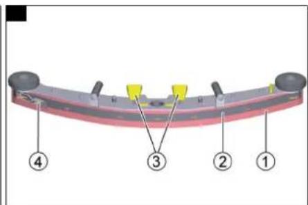
Turning over or replacing the suction lips
The suction lips must be turned over or replaced when worn out.
Note
The suction lips can be turned 3 times until all 4 edges are worn.
- Open the eccentric levers (2x).
- Remove the suction bar. Illustration V
① Squeegee blade
②Strap
③ Eccentric levers (2x)
④ Tension lock
- Open the tension lock.
- Remove the strap.
- Remove the squeegee blade.
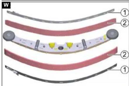
- Press the turned or new suction lips onto the knobs of the inner part of the suction bar. Illustration W
① Strap
② Sque
- Attach the strap.
- Fit the suction bar
- Close the eccentric levers (2x).
Replacing the roller brushes
- Pull the tab
Illustration Z
①Tab
2. Pivot open the squeegee blade side doors.
① Squeegee blade side doors
3. Pivot the yellow lever upwards. Illustration AA
① Bar
② Safety flap
4. Pivot away the safety flap.
5. Pull off the brush retaining plate.
6. Remove the roller brush.
7. Fit the new roller brush.
Note
When fitting the roller brush, note that it must be placed on the PIN provided in the brush tunnel.
Illustration AB
①PIN
-
Fit the brush retaining plate again.
-
Close the safety flap.
-
Pivot the latch downwards into the hook.
-
Pivot the squeegee blade side door closed.
Repeat the entire procedure at the other side.
Replacing squeegee blades
Illustration AG
①Tab
② Squeegee blade side doors
- Pull the tab.
- Pivot open the squeegee blade side doors.
- Unscrew the screws (6x).
Illustration AH
- Replace the squeegee blade.
- Reinstall the screws (6x).
- Close the squeegee blade holder again.
Replacing the disc brushes
- Pull the tab on the side doors. Illustration AF
①Bracket
- Pivot open the squeegee blade side doors.
- Push the bracket downwards.
- Pull the disc brush sideways and out from underneath the cleaning head.
- Hold the new disc brush under the cleaning head, then press upwards and latch it into position.
- Pivot the squeegee blade side doors closed again.
Additional maintenance work on the side scrubbing deck
Cleaning the brush
- Turn the brush clockwise until the brush holder springs are facing forward.
- Pull the brush holder springs apart.
Illustration AQ
①Brush holder springs
The brush falls out of the holder.
- Check the brush for foreign objects (e.g. parcel tape or foil).
- Clean the brush under running water.
- Pull the brush holder springs apart and fit the brush.
Checking the brush for wear and tear
The brush is worn out when the bristle length corresponds to the length of the yellow indicator bristle.
- Replace the brush (See Replacing the brush).
Replacing the brush
- Turn the brush clockwise until the brush holder springs are facing forward.
- Pull the brush holder springs apart.
Illustration AQ
①Brush holder springs
The brush falls out of the holder.
3. Fit the new brush.
4. Pull the brush holder springs apart and fit the brush.
Replacing the squeegee blade
- Unscrew the M6 x 12 screws (6x).
Illustration AR
①M6 x 12 screws
②Retaining plate
2. Remove the retaining plate and the squeegee blade.
3. Fit the new squeegee blade on the retaining plate.
4. Fasten the retaining plate using the M6 x 12 screws (6x).
Additional maintenance work for the Combo variant
△DANGER
Danger of crushing and shearing!
Danger of crushing and shearing due to running belt drives.
It is essential to close and lock the sweeping mechanism hood before you can put the device back into operation after maintenance work.
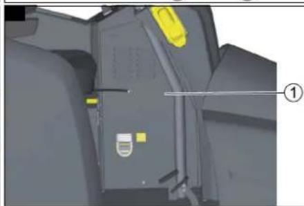
Checking the drive belt
- Fold the hood of the pre-sweeping unit forwards. Illustration K
- Remove the 4 screws from the protective plate.
-
Remove the protective plate.
-
Check the belt of the suction turbine for wear and correct fit.
Illustration L
① Pre-sweeping unit suction turbine belt
② Brush roller drive belt (Under the sheet metal cover)
5. Check the brush roller drive belt for wear and correct seating.
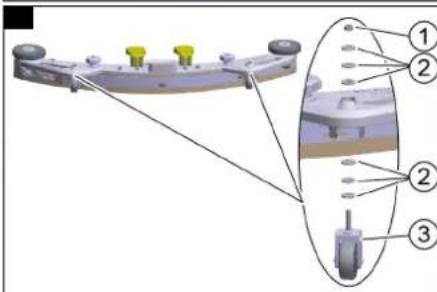
Checking the sweeping mechanism sealing strips
- Place the device on a level surface.
- Set the program selection switch to "0".
-
Use a chock to secure the device against rolling away.
-
Remove the waste containers from both sides.
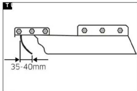
Front sealing strip
-
Unscrew the nuts (5x). Illustration R
-
Align the ground clearance of the sealing strip so that it bends to the rear by 35-40 mm at the ground. Illustration T
①Nut
- Tighten the nuts (5x).
Rear sealing strip
Adjust the ground clearance of the rear sealing strip so that it bends to the rear by 5 - 10mm at the ground. Illustration S - Replace the sealing strip if it is worn.
- Remove the roller brush (see chapter Replacing the roller brush).
- Unscrew the nuts (7x). Illustration R
① Nut
- Fit the new sealing strip.
- Tighten the nuts (7x).
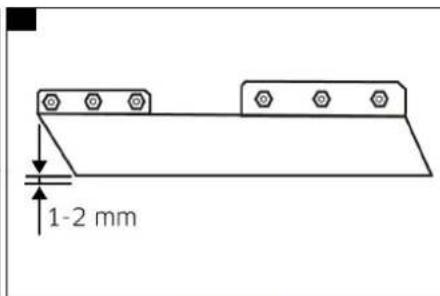
Side sealing strips - Release the fastening nuts. Illustration U
- Adjust the ground clearance by inserting an underlay 1-2 mm thick.
- Align the sealing strip.
- Tighten the nuts.
- Install the roller brush.
Replacing the dust filter
Illustration AC
① Dust filter housing cover
② Screw
③ Flange
- Release the lock of the sweeping mechanism hood by turning it inwards.
- Pivot up the sweeping mechanism hood.
- Remove the dust filter housing cover.
- Remove the screws (2x)
- Turn the flange anticlockwise and remove the dust filter bearing.
- Remove the dust filter.
- Fit the new dust filter so that the holes on the front point to the driver.
- Fit the dust filter bearing, turn clockwise and screw light.
- Fit the cover and latch into place.
- Close the sweeping mechanism hood.
- Secure the hood lock by turning it outwards.
Replacing the side brushes
- Unscrew the screws (3x).
Illustration AE
① Screws
2. Remove the side brush.
3. Slide on the new side brush.
4. Screw in and tighten the 3 screws.
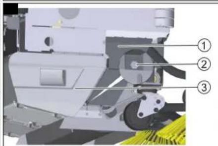
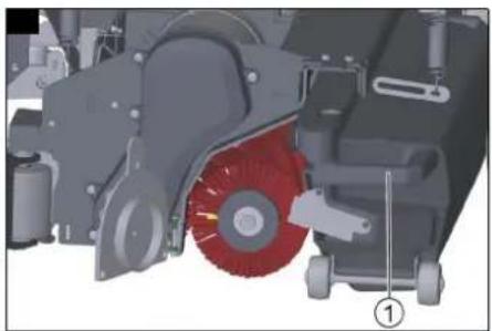
Replacing the roller brush
Illustration X
1 Sheet metal cover
② Screw
③ Waste container
1. Pull out the waste container.
2. Unscrew the screw.
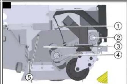
3. Pivot the sheet metal cover upwards and remove it. Illustration Y
① Bowden cable
② Swing arm bearing screw
③ Cover
④Rocker
⑤ Cover screws
- Unhook the Bowden cable.
- Unscrew the screw of the swing arm bearing.
- Pull off the rocker.
- Unscrew both screws of the cover and remove the cover.
- Remove the roller brush.
- Fit the new roller brush.
- Assemble the sweeping mechanism in the reverse order.
- Adjust the Bowden cable.
Frost protection
If there is a risk of frost:
-
Empty the fresh water tank and the waste water tank.
-
Park the device in a frost-protected room.
Troubleshooting guide
△DANGER
Risk of injury if the device is started unintentionally!
Unintentional starting of the device can cause injury to persons working on the device.
Remove the Intelligent Key prior to all work on the device.
Before carrying out any work, pull the mains plug of the internal charger out of the socket.
Disconnect the battery connector before performing any work.
△WARNING
Risk of injury from moving elements!
The suction turbine, side brushes and filter dedusting run on after switching off.
Do not carry out any work on the device until the components have come to a standstill.
-
Drain the waste water.
-
Drain the remaining fresh water.
Note
If the malfunction cannot be remedied with the following instructions, contact Customer Service.
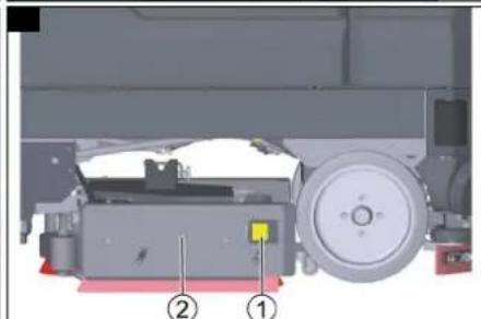
Replacing fuses
Only the automotive flat fuses with the following values may be replaced by the operator:
- 5A– Controller and emergency power supply
• 20A – Per stroke/accessory module supply
- 50A – Lift/Clean module 3 (Combo variant)
ATTENTION
Damage to the controller!
Improper replacement of the fuses can damage the controller.
Have defective pole fuses replaced only by the Customer Service. If pole fuses are defective, the operating conditions and the entire controller must be checked by the Customer Service.
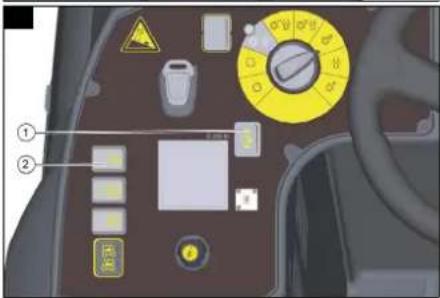
The controller is located below the control panel. To access the fuses, remove the cover on the left side of the footwell.
Note
The fuse assignment can be found on the inside of the cover.
Illustration AD
① Cover
- Unscrew the screw (3x).
- Remove the bar cover.
- Replace the fuse.
- Attach the cover.
Malfunctions with information shown on the display
If faults are shown on the display, proceed as follows:
● Fault display as a numerical code
In the event of a fault display with a numerical code, first reset the fault (the device):
a Set the program selection switch to "0".
b Wait until the display has switched off.
c Set the program selection switch to the previous program.
Carry out the appropriate remedial measures in the order given only if the error occurs again. The program selection switch must be in position "0" and the Intelligent Key must have been pulled out.
d If the error cannot be rectified, call Customer Service and state the error message.
● Fault display as text
a Follow the instructions on the display.
b Acknowledge the fault by pressing the info button.
Note
Error messages that are not listed in the following table indicate errors that cannot be rectified by the operator. In this case, please call Customer Service.
| Seat switch open! 1. Release the accelerator pedal.2. Adjust the driver's seat to the correct body weight.3. Relieve the driver's seat briefly so that the controller can check the function of the seat contact switch.4. Fully load the driver's seat. | |
| Release the accelerator pedal! 1. Release the accelerator pedal. | |
| No travel direction! 1. Contact customer service. | |
| Battery discharged! | 1. Charge the battery. |
| Battery voltage impermissible! | 1. Contact Customer Service |
| Fresh water tank empty! | 1. Refill the fresh water tank. |
| Brush pressure not reached! | 1. Check the brushes for wear and replace if necessary.2. Check the cleaning head functions: lower, raise. |
| Waste water full! | 1. Empty the waste water tank. |
| Brake defective! | 1. Stop driving the device.2. Contact Customer Service |
| Driving motor too hot! Cooling phase | 1. Set the safety switch to "0".2. Allow the device to cool down for at least 15 minutes.3. Contact Customer Service if this occurs repeatedly |
| Horn defective! | 1. Contact customer service. |
| CPU head too hot! Cooling phase | 1. Set the safety switch to "0".2. Allow the controller to cool down for at least 5 minutes.3. Significantly reduce the brush pressure on rough ground.4. Contact Customer Service if this occurs repeatedly. |
| Brush drive overloaded! | 1. Reduce the brush contact pressure.2. Check if foreign objects (e.g. parcel tape, pieces of wood) are blocking the brushes. |
| No travel direction! 1. Switch off the device.2. Push the direction switch back and forth a few times.3. Switch the device on.4. Contact customer service if the error persists. | |
Malfunctions without information shown on the display
| The device cannot be started | 1. Insert the battery plug.2. Turn the safety switch to "1".3. Insert the Intelligent Key.4. Check fuse F1, replace if necessary, (see chapterReplacing fuses).5. Check the batteries and charge if necessary. |
| The water quantity is insufficient | 1. Check the fresh water filling level, if necessary fill the tank completely so that the air is pressed out.2. Check the hoses for clogging and clean if necessary.3. Remove and clean the fresh water filter.4. Open the fresh water ball tap. |
| The suction performance is too low | 1. Close the lid on the waste water drain hose.2. Clean the seals between the waste water tank and the cover, check for leaks and replace if necessary.3. Clean the turbine filter.4. Clean the suction lips at the suction bar, turn over or replace if necessary.5. Check the suction hose for clogging and clean if necessary.6. Check the suction hose for leaks and replace if necessary.7. Check the adjustment of the suction bar. |
| The cleaning results are unsatisfactory | 1. Set the appropriate cleaning program for the cleaning task.2. Use suitable brushes for the cleaning task.3. Use a suitable detergent for the cleaning task.4. Reduce the driving speed.5. Adjust the contact pressure.6. Adjust the squeegee blades.7. Check the brushes for wear and replace if necessary.8. Check the water output. |
| The brushes do not rotate 1. Reduce the contact pressure. | 2. Check if the brushes are blocked by a foreign body and remove the foreign body if necessary. |
| The optional all-round light and/or the working light do not light up | 1. Check fuse F3, replace if necessary, (see chapterReplacing fuses). |
| Error K1/109 1. Switch off the device. | 2. Wait one minute.3. Switch the device on again. |
Additional malfunctions on the Combo variant
| The device does not sweep properly | 1. Check the roller brush and the side brushes for wear, replace if necessary.2. If the roller brush does not turn, check the drive belt, clean if necessary.3. Check the function of the coarse dirt flap.4. Check the sealing strips for wear, adjust or replace if necessary. |
| The sweeping mechanism creates a dust cloud | 1. Empty the waste container.2. Check the drive belts for the sweeping mechanism suction turbine.3. Check the sealing sleeve on the suction fan.4. Check the dust filter, clean or replace if necessary.5. Check the filter box seal.6. Check the sealing strip for wear, adjust or replace if necessary. |
| The cleaning result when sweeping in the edge area is unsatisfactory | 1. Check the height adjustment of the side brushes, adjust if necessary.2. Replace the side brushes. |
Technical data
| B 260 RI(R100) | B 260 RICombo (R100) | B 260 RI(R 120) | B 260 RICombo (R 120) | B 260 RI(D100) | B 260 RICombo (D100) | |||||
| General | ||||||||||
| Travel speed (max.) km/h 10 10 10 10 10 10 | ||||||||||
| Transport speed km/h 10 10 10 10 10 10 | ||||||||||
| R | e | v | e | r | s | e | s | p | e | e |
| Permissible braking distance on level ground at max. travel speed of 10 km/h | 1,9 | 1,9 | 1,9 | 1,9 | 1,9 | 1,9 | ||||
| Application time depending on brush head, brush contact pressure and roughness of the ground | 5 | 4,5 | 5 | 4,5 | 5 | 4,5 | ||||
| Theoretical surface coverage | m^2/h | 10000 | 10000 | 12000 | 12000 | 10000 | 10000 | |||
| Theoretical surface coverage with side scrubbing deck | m^2/h | 11200 | --- | --- | --- | 11200 | --- | |||
| Theoretical surface coverage with 2 side brushes | m^2/h | 11500 | 11500 | 13400 | 13400 | 11500 | 11500 | |||
| Practical surface coverage with brush head | m^2/h | 7000 7000 8400 | 8400 | 7000 7000 | ||||||
| Fresh/waste water tank volume | I | 260 | 260 | 260 | 260 | 260 | 260 | |||
| Coarse dirt container capacity | I 26 26 32 32 --- | --- | ||||||||
| Detergent tank (Dose option) | I 10 10 10 10 10 10 | |||||||||
| Detergent dosing range (from - to) | % | 0-3 | 0-3 | 0-3 | 0-3 | 0-3 | 0-3 | |||
| Minimum water dosing quantity | l/min | 0,9 | 0,9 | 0,9 | 0,9 | 0,9 | 0,9 | |||
| Maximum water dosing quantity | l/min | 9 | 9 | 9 | 9 | 9 | 9 | |||
| Max. surface pressure (incl. driver, water) | N/mm^2 | 1,33 | 1,33 | 1,33 | 1,33 | 1,33 | 1,33 | |||
| Device performance data | ||||||||||
| Nominal voltage | V | 36 | 36 | 36 | 36 | 36 | 36 | |||
| Battery capacity | Ah | 630 | 630 | 630 | 630 | 630 | 630 | |||
| Mean power input | W | 7500 | 8900 | 7500 | 8900 | 7500 | 8900 | |||
| Driving motor power | W | 2200 | 2200 | 2200 | 2200 | 2200 | 2200 | |||
| Suction motor power | W | 2x840 | 2x840 | 2x840 | 2x840 | 2x840 | 2x840 | |||
| Brush motor power | W | 2x 1100 | 2x 1100 | 2x 1100 | 2x 1100 | 2x 1100 | 2x 1100 | |||
| Charging time with empty battery | h | 10 | 10 | 10 | 10 | 10 | 10 | |||
| Brush roller drive power | W | --- | 600 | --- | 600 | --- | 600 | |||
| Side brushes power (option) | W | 110 | 110 | 110 | 110 | 110 | 110 | |||
| Sweeping mechanism suction turbine power | W | --- | 600 | --- | 600 | --- | 600 | |||
| Vacuuming | ||||||||||
| Suction performance, air quantity | l/s | 28 x 2 | 28 x 2 | 28 x 2 | 28 x 2 | 28 x 2 | 28 x 2 | |||
| Suction performance, vacuum | kPa (mbar) | 14 (140) | 14 (140) | 14 (140) | 14 (140) | 14 (140) | 14 (140) | |||
| Filter area of dust filter | m^2 | --- | 4 | --- | 4 | --- | 4 | |||
| Vacuum turbine/suction bar | kPa (mbar) | 22/11 (220/110) | 22/11 (220/110) | 22/11 (220/110) | 22/11 (220/110) | 22/11 (220/110) | 22/11 (220/110) | |||
| Cleaning brushes | ||||||||||
| Brush diameter | mm | 160 | 160 | 160 | 160 | 510 | 510 | |||
| Brush length | mm | 914 | 914 | 1118 | 1118 | --- | --- | |||
| Brush speed | l/min | 1250 | 1250 | 1250 | 1250 | 140 | 140 | |||
| Side scrubbing deck brush speed | l/min | 140 | --- | --- | --- | 140 | --- | |||
| Side scrubbing deck brush diameter | mm | 300 | --- | --- | --- | 300 | --- | |||
| B 260 RI(R100) | B 260 RICombo (R100) | B 260 RI(R 120) | B 260 RICombo (R 120) | B 260 RI(D100) | B 260 RICombo (D100) | ||
| Roller brush diameter mm --- 285 --- 285 --- 285 | |||||||
| Roller brush width mm --- 710 --- 710 --- 710 | |||||||
| Roller brush speed 1/min --- 610 --- 610 --- 610 | |||||||
| Side brush diameter mm 450 450 450 450 450 450 | |||||||
| Dimensions | |||||||
| Length mm 1925 2560 1925 2560 1925 2560 | |||||||
| Width (without suction bar) mm 1040 1040 1040 1040 1040 | |||||||
| Width (with suction bar) mm 1140 1140 1340 1340 1140 1140 | |||||||
| Height mm 1565 1565 1565 1565 1565 | |||||||
| Height (with overhead guard, flashing beacon) | mm | 2200 | 2200 | 2200 | 2200 | 2200 | 2200 |
| Working width with side scrubbing deck | mm | 1120 | 1120 | 1120 | 1120 | 1120 | 1120 |
| Working width with side brushes | mm 1150 1180 1340 1340 1150 1180 | ||||||
| Turning radius with smallest equipment(180°) | mm | 2120 | 2950 | 2120 | 2950 | 2120 | 2950 |
| Battery compartment size (LxWxH) | mm | 840 x 625 x 520 | 840 x 625 x 520 | 840 x 625 x 520 | 840 x 625 x 520 | 840 x 625 x 520 | 840 x 625 x 520 |
| Front wheel, width | mm 132 132 | 132 132 132 132 | |||||
| Front wheel, diameter (outside) | mm 300 300 | 300 300 300 300 | |||||
| Rear wheel, width | mm 108 108 | 108 108 108 108 | |||||
| Rear wheel, diameter (outside) | mm 375 375 | 375 375 375 375 | |||||
| Weight | |||||||
| Approved total weight | kg | 1840 | 2020 | 1840 | 2020 | 1840 | 2020 |
| Transport weight (with 630 Ah battery, 75 kg driver, average Brush head) | kg | 1460 1944 1460 1944 1460 1944 | |||||
| Weight, ready for operation (with batteries and full tank) | kg | 1641 1845 1641 1845 1641 1845 | |||||
| Brush contact pressure | kg | 150 150 150 150 130 130 | |||||
| Brush contact pressure | g/cm2 | 210 210 168 168 42 | 42 | ||||
| Load per unit area (with driver and full fresh water tank) | |||||||
| Sweeping mechanism wheel surface load | N/cm2 | --- --- --- --- --- --- | |||||
| Load per unit area, front wheel | N/cm2 | 207 207 207 207 207 | |||||
| Load per unit area, rear wheel | N/cm2 | 60 | 60 | 60 | 60 | 60 | 60 |
| Charger offboard ex works | |||||||
| Cable length | mm 3000 3000 3000 3000 3000 3000 | ||||||
| Voltage | V | 230 | 230 | ||||
| Frequency range | Hz | 50/60 | 50/60 | 50/60 | 50/60 | 50/60 | 50/60 |
| Dimensions | mm | 420 x 260 x 115 | 420 x 260 x 115 | 420 x 260 x 115 | 420 x 260 x 115 | 420 x 260 x 115 | 420 x 260 x 115 |
| Weight | kg | 10 | 10 | 10 | 10 | 10 | 10 |
| Protection class | IP 21 | IP 21 | IP 21 | IP 21 | IP 21 | IP 21 | |
| Plug type | Schuko | Schuko | Schuko | Schuko | Schuko | Schuko | |
| Charging current | A | 65 | 65 | 65 | 65 | 65 | 65 |
| Ambient conditions | |||||||
| Maximum ambient temperature | °C | 40 | 40 | 40 | 40 | 40 | 40 |
| Minimum ambient temperature | °C | 5 | 5 | 5 | 5 | 5 | 5 |
| Maximum water temperature | °C | 60 | 60 | 60 | 60 | 60 | 60 |
| Incline | |||||||
| Maximum gradient (for transport travel) | % | 15 | 10 | 15 | 10 | 15 | 10 |
| Maximum gradient (In scrub mode) | % | 15 | 10 | 15 | 10 | 15 | 10 |
| Maximum short term gradient (Max. 10 m) | % | 25 | 25 | 25 | 25 | 25 | 25 |
| Determined values in acc. with EN 60335-2-72 | |||||||
| Total vibration value | m/s2 | 0,41 | 0,41 | 0,41 | 0,41 | 0,41 | 0,41 |
| Arm total vibration value | m/s2 | 0,4 | 0,4 | 0,4 | 0,4 | 0,4 | 0,4 |
| Seat surface total vibration value | m/s2 | 0,1 | 0,1 | 0,1 | 0,1 | 0,1 | 0,1 |
| Hand-arm vibration value, uncertainty K | m/s2 | 0,2 | 0,2 | 0,2 | 0,2 | 0,2 | 0,2 |
| Seat vibration value, uncertainty K | m/s2 | 0,1 | 0,1 | 0,1 | 0,1 | 0,1 | 0,1 |
| Sound pressure level | dB(A) | 73 | 73 | 73 | 73 | 73 | 73 |
| Uncertainty KpA | dB(A) | 3 | 3 | 3 | 3 | 3 | 3 |
| Sound power level LWA + uncertainty KWA | dB(A) | 94 | 94 | 94 | 94 | 94 | 94 |
| Protection class | IPX3 | IPX3 | IPX3 | IPX3 | IPX3 | IPX3 | |
| Side scrubbing deck | |||||||
| Power | W | 260 260 260 260 260 260 | |||||
| Contact pressure | kg | 9,7 | 9,7 | 9,7 | 9,7 | 9,7 | 9,7 |
| Contact pressure | N/mm2 | 0,00239 | 0,00239 | 0,00239 | 0,00239 | 0,00239 | 0,00239 |
Subject to technical modifications.
EU Declaration of Conformity
We hereby declare that the machine described below complies with the relevant basic safety and health requirements in the EU Directives, both in its basic design and construction as well as in the version placed in circulation by us. This declaration is invalidated by any changes made to the machine that are not approved by us.
Product: Floor cleaning ride-on machine
Type: 1.480-xxx / 2.480-xxx
Currently applicable EU Directives
2006/42/EC (+2009/127/EC)
2014/30/EU
2014/53/EU (TCU)
Harmonised standards used
EN 60335-1
EN 60335-2-72
EN 62233: 2008
EN 55012: 2007 + A1: 2009
EN 61000-6-2: 2005
TCU
EN 300 328 V2.2.2
EN 300 330 V2.1.1
EN 300 440 V2.1.1
EN 301 511 V12.5.1
National standards used
The signatories act on behalf of and with the authority of the company management.

H. Jenner
Chairman of the Board of Management

S. Reiser
Director Regulatory Affairs & Certification
Documentation supervisor:
S. Reiser
Alfred Kärcher SE & Co. KG
Alfred-Kärcher-Str. 28 - 40
71364 Winnenden (Germany)
Ph.: +49 7195 14-0
Fax: +49 7195 14-2212
Winnenden, 2021/03/01
Contenu
Type : 1.480-xxx / 2.480-xxx
2006/42/CE (+2009/127/CE)
2014/30/UE
2014/53/EU (TCU)

H. Jenner
Chairman of the Board of Management

S. Reiser
Director Regulatory Affairs & Certification
71364 Winnenden (Germany)
Tipo: 1.480-xxx / 2.480-xxx
71364 Winnenden (Germany)
Tel.: +49 7195 14-0
Fax: +49 7195 14-2212
Winnenden, 01/03/2021
2006/42/CE (+2009/127/CE)
2014/30/UE
2014/53/UE (TCU)
Chairman of the Board of Management

S. Reiser
Director Regulatory Affairs & Certification
71364 Winnenden (Germany)
Tel.: +49 7195 14-0
Fax: +49 7195 14-2212
Winnenden, 01/03/2021
Índice
③ Vassoura lateral***
④ Caixa do filtro
- Soltar as porcas (5x).
Figura R
- Apertar as porcas (5x).
2006/42/CE (+2009/127/CE)
2014/30/UE
2014/53/UE (TCU)

H. Jenner
Chairman of the Board of Management

S. Reiser
Director Regulatory Affairs & Certification
Winnenden, 01/03/2021
Inhoud

H. Jenner
Chairman of the Board of Management

S. Reiser
Director Regulatory Affairs & Certification
71364 Winnenden (Germany)
Tel.: +49 7195 14-0
Fax: +49 7195 14-2212
Winnenden, 2021/03/01
İçindekiler
Genel uyarılar 80
Fonksiyon....80
Beyaz Intelligent Key
2006/42/AT (+2009/127/AT)
2014/30/AB
2014/53/EU (TCU)

H. Jenner
Chairman of the Board of Management

S. Reiser
Director Regulatory Affairs & Certification
Winnenden, 2021/03/01
Innehåll
Allmän information 90
Funktion 90
Typ: 1.480-xxx / 2.480-xxx

H. Jenner
Chairman of the Board of Management

S. Reiser
Director Regulatory Affairs & Certification
D-71364 Winnenden (Germany)
Tfn: +49 7195 14-0
Fax: +49 7195 14-2212
Winnenden, 01.03.2021
Sisältö
Yleisiä ohjeita 100
Toiminta 100
Chairman of the Board of Management
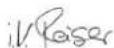
S. Reiser
Director Regulatory Affairs & Certification
71364 Winnenden (Germany)
Puh.: +49 7195 14-0
I tillegg for Combo-varianten:
2006/42/EF (+2009/127/EF)
2014/30/EU
2014/53/EU (TCU)
Anvendte harmoniserte standarder
EN 60335-1
EN 60335-2-72
EN 62233: 2008
EN 55012: 2007 + A1: 2009
EN 61000-6-2: 2005
TCU
EN 300 328 V2.2.2
EN 300 330 V2.1.1
EN 300 440 V2.1.1
EN 301 511 V12.5.1

Chairman of the Board of Management

S. Reiser
Director Regulatory Affairs & Certification
71364 Winnenden (Germany)
Tlf.: +49 7195 14-0
Winnenden, 2021/03/01
Indhold
Faresituation under driften
2006/42/EF (+2009/127/EF)
2014/30/EU
2014/53/EU (TCU)

H. Jenner
Chairman of the Board of Management
S. Reiser
Director Regulatory Affairs & Certification
71364 Winnenden (Germany)
Tlf.: +49 7195 14-0
Fax: +49 7195 14-2212
Winnenden, 2021/03/01
Sisukord
Üldised juhised.... 129
Funktsioon 129
Sihtotstarbeline kasutamine.... 129
Imitala monteerimine
● "down": Langetamine
● "OFF": Peatamine
2006/42/EÜ (+2009/127/EÜ)
2014/30/EL
2014/53/EL (TCU)
Chairman of the Board of Management
S. Reiser
Director Regulatory Affairs & Certification
71364 Winnenden (Germany)
Tel: +49 7195 14-0
Winnenden, 2021/03/01
Saturs
Chairman of the Board of Management

S. Reiser
Director Regulatory Affairs & Certification
Typ: 1.480-xxx / 2.480-xxx
2006/42/WE (+2009/127/WE)
2014/30/UE
2014/53/EU (TCU)

Jenner
Chairman of the Board of Management

S. Reiser
Director Regulatory Affairs & Certification
71364 Winnenden (Germany)
Tel.: +49 7195 14-0
Tipus: 1.480-xxx / 2.480-xxx

H. Jenner
Chairman of the Board of Management

S. Reiser
Director Regulatory Affairs & Certification
Winnenden, 2021/03/01
Obsah
2006/42/ES (+2009/127/ES)
2014/30/EU
2014/53/EU (TCU)

H. Jenner
Chairman of the Board of Management

S. Reiser
Director Regulatory Affairs & Certification
Winnenden, 2021/03/01
Obsah
Všeobecné upozornenia 189
Funkcia 189
Typ: 1.480-xxx / 2.480-xxx
2006/42/ES (+2009/127/ES)
2014/30/EÚ
2014/53/EÚ (TCU)

H. Jenner
Chairman of the Board of Management

S. Reiser
Director Regulatory Affairs & Certification
71364 Winnenden (Germany)
Tel.: +49 7195 14-0
Fax: +49 7195 14-2212
Winnenden, 01.03.2021
Kazalo
Tip: 1.480-xxx / 2.480-xxx
Zadevne EU-direktive
2006/42/ES (+2009/127/ES)
2014/30/EU
2014/53/EU (TCU)

H. Jenner
Chairman of the Board of Management

S. Reiser
Director Regulatory Affairs & Certification
Winnenden, 1. 3. 2021
Cuprins
Indicatii generale.... 209
Functionarea 209
Tip: 1.480-xxx / 2.480-xxx
Directive UE relevante
2006/42/UE (+2009/127/UE)
2014/30/UE
2014/53/UE (TCU)
Norme armonizate aplicate
EN 60335-1
EN 60335-2-72
EN 62233: 2008
EN 55012: 2007 + A1: 2009
EN 61000-6-2: 2005
TCU
EN 300 328 V2.2.2
EN 300 330 V2.1.1
EN 300 440 V2.1.1
EN 301 511 V12.5.1
Standarde nationale aplicate

H. Jenner
Chairman of the Board of Management

S. Reiser
Director Regulatory Affairs & Certification
71364 Winnenden (Germania)
Tel.: +49 7195 14-0
Fax: +49 7195 14-2212
Winnenden, 2021/03/01
Sadržaj
Opće napomene 219
Funkcija.... 219
Tip: 1.480-xxx / 2.480-xxx
2006/42/EZ (+2009/127/EZ)
2014/30/EU
2014/53/EU (TCU)
Primijenjene uskladene norme
EN 60335-1
EN 60335-2-72
EN 62233: 2008
EN 55012: 2007 + A1: 2009
EN 61000-6-2: 2005
TCU
EN 300 328 V2.2.2
EN 300 330 V2.1.1
EN 300 440 V2.1.1
EN 301 511 V12.5.1
Primijenjene nacionalne norme

Chairman of the Board of Management

S. Reiser
Director Regulatory Affairs & Certification
Opunomoćenik za dokumentaciju:
S. Reiser
Alfred Kärcher SE & Co. KG
Alfred-Kärcher-Str. 28 - 40
71364 Winnenden (Njemačka)
Tel.: +49 7195 14-0
Telefaks: +49 7195 14-2212
Winnenden, 01.03.2021
Sadržaj
Opšte napomene 229
Funkcija.... 229
Namenska upotreba.... 229
Zaštita životne sredine 229
Garancija 230
Pribor i rezervni delovi 230
Obim isporuke 230
Sigurnosne napomene 230
Opis uređaja 230
Montaža 231
Rad 232
Završetak rada 233
Sivi Intelligent Key 234
Žuti Intelligent Key 234
Beli inteligentni ključ 234
Transport.... 235
Skladištenje.... 235
2006/42/EZ (+2009/127/EZ)
2014/30/EU
2014/53/EU (TCU)
Primenjene harmonizovane norme
EN 60335-1
EN 60335-2-72
EN 62233: 2008
EN 55012: 2007 + A1: 2009
EN 61000-6-2: 2005
TCU
EN 300 328 V2.2.2
EN 300 330 V2.1.1
EN 300 440 V2.1.1
EN 301 511 V12.5.1
Primenjene nacionalne norme
Potpisnici deluju po nalogu i uz punomoć upravnog odbora.

H. Jenner
Chairman of the Board of Management

S. Reiser
Director Regulatory Affairs & Certification
Lice ovlašćeno za dokumentaciju:
S. Reiser
Alfred Kärcher SE & Co. KG
Alfred-Kärcher-Str. 28 - 40
71364 Winnenden (Germany)
Tel.: +49 7195 14-0
Winnenden, 2021/03/01
Περιεχόμενα

H. Jenner
Chairman of the Board of Management

S. Reiser
Director Regulatory Affairs & Certification
71364 Winnenden (Germany)
Tnλ.: +49 7195 14-0
Φαξ: +49 7195 14-2212
Winnenden, 2021/03/01
Содержание
Тип: 1.480-xxx / 2.480-xxx

Chairman of the Board of Management

S. Reiser
Director Regulatory Affairs & Certification
71364 Winnenden (Germany)
Тел.: +49 7195 14-0
Факс: +49 7195 14-2212

H. Jenner
Chairman of the Board of Management

S. Reiser
Director Regulatory Affairs & Certification
71364 Winnenden (Germany)
Тел.: +49 7195 14-0
Факс: +49 7195 14-2212
Тип: 1.480-xxx / 2.480-xxx

H. Jenner
Chairman of the Board of Management
S. Reiser
Director Regulatory Affairs & Certification
71364 Winnenden (Germany)
Тел.: +49 7195 14-0
Факс: +49 7195 14-2212
Виненден, 2021/03/01
目录
一般性注意事项 284 功能 284
按规定使用 284
环境保护 284
质量保证 281
附件和备件 284
供货范围 284
安全提示 281
设备说明 284
安装 285
运行 286
结束运行 287
灰色智能钥匙 287
黄色智能钥匙 288
白色智能钥匙 288
运输 288
存放 288
保养和维护 288
故障时的帮助 289
技术数据 291
欧盟一致性声明 292
般性注意事项
www.kaercher.com/REACH
质量保证
类型:1.480-xxx/2.480-xxx
相关的欧盟指令
2006/12/EC (-2009/127/EC)
2014/30/EU
2014/53/EC (TCU)
应用的协调标准
EN 60335 1
EN 60335-2-72
EN 62233: 2008
EN 55012: 2007 + A1: 2009
EN 61000-6-2: 2005
TCU
EN 300 328 V2.2.2
EN 300 330 V2.1.1
EN 300 410 V2.1.1
EN 301 511 V12.5.1
适用的国家标准

H. Jenner
Chairman of the Board of Management

S. Reiser
Director Regulatory Affairs & Certification
文档全权代表:
S. Reiser
Alfred Kärcher SE & Co. KG
Alfred-Kärcher-Str. 28 - 40
71364 Winnenden (德国)
电话:+49 7195 14-0
传真:+49 7195 14-2212
Winnenden, 2021/03/01
차례
일반 지시 사항 293
293
기성에 따른 사용 293
환경보호 293
보증 293
부대 용품 및 에비품 293
공급 범위 293
안진 지침 293
장비 설명 293
조립 294
직농 295
자동 종료 296
회색 인텐리진트 키 297
황새 인텔리전드 키 297
희색 인텐리전트 키 297
운반 298
보관 298
관리 및 정비 298
장애 발생 시 조치 299
기술 데이터 300
EU 직합성 선언시 302
②유지환(retaining plate)
유형:1.480-xxx/2.480-xxx
관련 EU 지침
2006/12/EC(+2009/127/EC)
2014/30/EU
2014/53/EU (TCU)
적용되는 통일 표준
EN 60335-1
EN 60335-2-72
EN 62233: 2008
EN 55012: 2007 + A1: 2009
EN 61000-6-2:2005
TCU
EN 300 328 V2.2.2
EN 300 330 V2.1.1
EN 300 440 V2.1.1
EN 301 511 V12.5.1
적용되는 국가 표준

H. Jenner
Chairman of the Board of Management
S. Reiser
Director Regulatory Affairs & Certification
문서 작성 책임자:
S. Reiser
Alfred Kärcher SE & Co. KG
Alfred-Kärcher-Str. 28 - 40
71364 Winnenden (Germany)
전화:+49 7195 14-0
underscores: +49 7195 14-2212
Winnenden, 2021/03/01
目次
一般的な注意事項…… 302
機能.... 302
規定に沿った使用.... 302
環境保護.... 302
保证.... 302
アクセサリーとスペアパーツ…… 302
同梱品 302
安全注意事项…… 302
機器に関する説明…… 303
取り付け…… 304
運転 305
運転の終了…… 306
灰色のインテリジェントキー…… 306
黄色のインテリジェントキー…… 307
白いインテリジェントキー…… 307
报送.... 307
保管 308
お手入れとメンテナンス…… 308
障害発生時のサポート…… 309
技術データ 310
凡準拠宣言.... 312
一般的な注意事項
デバイスを初めて使用する前に、この
オリジナル取扱説明書および付属すい
型式:1.480-xxx/2.480-xxx
関連するEU指令
2006/42/EG (-2009/127/EC)
2014/30/EU
2014/53/EU (TCU)
適用された調和規格
EN 60335-1
EN 60335-2-72
EN 62233: 2008
EN 55012: 2007 + A1: 2009
EN 61000-6-2:2005
TCU(テレマティクス制御ユニット)
EN 300 328 V2.2.2
EN 300 330 V2.1.1
EN 300 440 V2.1.1
EN 301 511 V12.5.1
使用国の規格

H. Jenner
Chairman of the Board of Management

S. Reiser
Director Regulatory Affairs & Certification
文書の全権委員:
S. Reiser
Alfred Kärcher SE & Co. KG
Alfred Kärcher Str. 28 - 40
71364 Winnenden (Germany)
電話番号:+49 7195 14-0
:1.480-xxx / 2.480-xxx

H. Jenner
Chairman of the Board of Management

S. Reiser
Director Regulatory Affairs & Certification
وكيل التوثيق:
إس رایزر
Alfred Kärcher SE & Co. KG
Alfred-Kärcher-Str. 28 - 40
71364
Winnenden, 2021/03/01
percentage of the country
natural_image
Black and white line drawing of a hand giving a thumbs-up gesture (no text or symbols)THANK YOU!
Register your product and benefit from many advantages.
www.kaercher.com/welcome ★★★★★

Rate your product and tell us your opinion.
natural_image
Icon showing a gear and wrench inside a square frame (no text or symbols)2-2-SC-A4-GS-aw19869
www.kaercher.com/dealersearch
Alfred Kärcher SE & Co. KG
Alfred-Kärcher-Str. 28-40
71364 Winnenden (Germany)

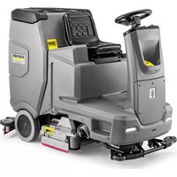
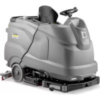
- Inhalt
- Contents
- General notes
- Function
- Note
- Intended use
- Environmental protection
- Notes on the content materials (REACH)
- Warranty
- Accessories and spare parts
- Scope of delivery
- Safety instructions
- △WARNING
- Safety devices
- △CAUTION
- Safety switch
- Seat switch
- Warning symbols
- △DANGER
- Symbols on the charger
- Risk of fire
- Description of the device
- Device overview, front
- Illustration B
- Device overview, rear
- Illustration A
- Device overview, seat
- Illustration C
- Device overview, waste water tank
- Illustration D
- Device overview, pedals
- Illustration AP
- Device overview, pre-sweeping unit
- Illustration E
- Type plate
- Illustration AJ
- Control panel
- Illustration F
- Program switch
- Illustration G
- Symbols on the device
- Pictograms on the display
- Installation
- Batteries
- Fitting and connecting batteries
- ATTENTION
- Risk of damage to the control electronics!
- Danger to life from fire or explosion if batteries are deeply discharged!
- Charging the battery
- Danger of death from electric shock!
- After the charging process
- Low-maintenance batteries (wet batteries)
- Refilling discharged batteries with water
- Using water with additives
- Battery Indicator
- Unpacking
- Illustration H
- Pushing the device off the pallet
- Driving off the pallet
- Installing he brushes
- BD Variant
- BR variant
- Installing the suction bar
- Operation
- Falling objects
- Risks during operation
- Switching the device on
- Checking the parking brake
- Danger of death due to defective parking brake!
- Checking the foot brake
- Danger of accident due to defective foot brake!
- Driving
- Lack of braking
- No braking effect during operation
- Careless driving
- Adjusting the driver's seat
- Illustration J
- Adjusting the steering wheel
- Checking the lint filter
- Damage to the suction turbine!
- Pushing the device
- Risk of injury from rolling device!
- Illustration AK
- Filling with fresh water
- Filling fresh water
- Filling fresh water with the fresh water tank automatic filling system (option)
- Filling with detergent
- Notes on detergents
- Unsuitable detergents
- Filling the detergent into the fresh water tank
- Danger of clogging
- Filling detergent with a dosing device
- (option)
- Adjusting parameters (yellow Intelligent key)
- Adjusting the suction bar
- Adjusting the inclination of the suction bar
- Illustration N
- Sweeping (Combo variant only)
- Moving parts
- Improper use of the device when sweeping
- Coarse dirt flap
- Risk of injury from waste!
- Ending sweeping
- Side scrubbing deck (option)
- Illustration AS
- Finishing operation
- Finishing cleaning
- Emptying the waste water tank
- Emptying the waste container
- Illustration AI
- Draining fresh water
- Cleaning solution in the fresh water tank
- Shutting down the device
- Grey Intelligent Key
- Transport journey
- Resetting the maintenance counter
- Resetting the counter
- Delete the day counter:
- Key management
- Choosing the brush shape
- After-running time
- Standard setting
- Setting the language
- Switch menu
- Set maximum travel speed
- Factory setting
- Adjusting parameters for cleaning programs
- Yellow Intelligent Key
- Authorisation management
- White intelligent key
- Programming the white Intelligent Key
- Operation with the white Intelligent Key
- Transport
- Failure to observe the weight
- Storage
- Frost
- Care and maintenance
- Risk of injury from the device!
- ⚠ WARNING
- Maintenance intervals
- Each time after use
- Risk of damage!
- Weekly
- Monthly
- Quarter-yearly
- Annually
- Safety inspection/maintenance contract
- Maintenance work
- Cleaning the waste water tank
- Turning over or replacing the suction lips
- Replacing the roller brushes
- Illustration Z
- Replacing squeegee blades
- Illustration AG
- Illustration AH
- Replacing the disc brushes
- Additional maintenance work on the side scrubbing deck
- Cleaning the brush
- Illustration AQ
- Checking the brush for wear and tear
- Replacing the brush
- Replacing the squeegee blade
- Illustration AR
- Additional maintenance work for the Combo variant
- Checking the drive belt
- Illustration L
- Checking the sweeping mechanism sealing strips
- Replacing the dust filter
- Illustration AC
- Replacing the side brushes
- Illustration AE
- Replacing the roller brush
- Illustration X
- ⑤ Cover screws
- Frost protection
- Troubleshooting guide
- Replacing fuses
- ① Cover
- Malfunctions with information shown on the display
- EU Declaration of Conformity
- National standards used
- Contenu
- Índice
- Figura R
- Inhoud
- İçindekiler
- Beyaz Intelligent Key
- Innehåll
- Sisältö
- Anvendte harmoniserte standarder
- TCU
- Indhold
- Faresituation under driften
- Sisukord
- Imitala monteerimine
- Saturs
- Obsah
- Kazalo
- Cuprins
- Directive UE relevante
- Norme armonizate aplicate
- Standarde nationale aplicate
- Sadržaj
- Primijenjene uskladene norme
- Primijenjene nacionalne norme
- Primenjene harmonizovane norme
- Primenjene nacionalne norme
- Περιεχόμενα
- Содержание
- 目录
- 般性注意事项
- 质量保证
- 차례
- 관련 EU 지침
- 적용되는 통일 표준
- 目次
- 一般的な注意事項
- THANK YOU!
Brand : Kärcher
Model : B 260 RI Bp
Category : Industrial floor scrubber