
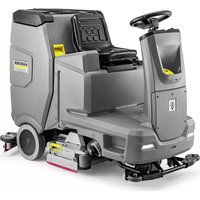
B 110 R Classic - Industrial floor scrubber Kärcher - Free user manual and instructions
Find the device manual for free B 110 R Classic Kärcher in PDF.

 FR
FR
 BG
BG
 CS
CS
 DA
DA
 DE
DE
 EL
EL
 EN
EN
 ES
ES
 ET
ET
 FI
FI
 HU
HU
 IT
IT
 JA
JA
 KO
KO
 LT
LT
 LV
LV
 NL
NL
 NO
NO
 PL
PL
 PT
PT
 RO
RO
 RU
RU
 SK
SK
 SL
SL
 SV
SV
 TR
TR
 UK
UK
 ZH
ZH
| Product type | Industrial scrubber dryer with driver seat |
| Brand | Kärcher |
| Model | B 110 R Classic |
| Cleaning head | R (roller) or D (disc) depending on version |
| Dimensions (L x W x H) | 1660 x 1035 x 1480 mm |
| Empty weight | 380 kg |
| Typical operating weight | 590 kg |
| Maximum permissible weight | 720 kg |
| Rated voltage | 24 V |
| Battery capacity | 170 Ah (5 h) |
| External charger | 230 V, 50-60 Hz, 50 A |
| Fresh water tank volume | 130 L |
| Dirty water tank volume | 110 L |
| Coarse dirt tank volume | 1.8 L (R head) |
| Working width | 750 mm |
| Suction bar width | 1000 mm |
| Theoretical area performance | 4500 m²/h |
| Practical area performance | 3150 m²/h |
| Driving/cleaning speed | 6 km/h |
| Transport speed | 6 km/h |
| Reverse speed | 4 km/h |
| Max inclination working area | 10 % |
| Short distance inclination (max 10 m) | 22 % |
| Sound pressure level (normal) | 63.6 dB(A) |
| Sound power level (normal) | 78.7 dB(A) |
| Operating temperature | +5 °C to +40 °C |
| Max water temperature | 50 °C |
| Protection type | IPX3 |
| Main functions | Water cleaning, polishing, suction, brushing |
| Safety | Safety switch, seat switch, thermal protection |
| Maintenance and cleaning | Cleaning filters, suction lips, brushes, draining tanks |
| Spare parts and repairability | Brushes, suction lips, filters, batteries, charger |
Frequently Asked Questions - B 110 R Classic Kärcher
User questions about B 110 R Classic Kärcher
0 question about this device. Answer the ones you know or ask your own.
Ask a new question about this device
Download the instructions for your Industrial floor scrubber in PDF format for free! Find your manual B 110 R Classic - Kärcher and take your electronic device back in hand. On this page are published all the documents necessary for the use of your device. B 110 R Classic by Kärcher.
USER MANUAL B 110 R Classic Kärcher
Polish 152
Hungarian 163
Czech 172
Slovak 182
Slovenian 192
Romanian 202
Croatian 212
Serbian 222
Greek 232
Russian 243
Ukrainian 254
Bulgarian 265
Chinese 276
Japanese 286
Korean 295
Contents
1 Horn
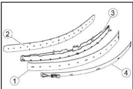
1 Tension strap 2 Board
3 Block
4 Square timber
1 Release lever
1 Screw
2 Nut
3 Spirit level
Storage
CAUTION
1 Float
O
Chairman of the Board of Management
S. Reiser
Director Regulatory Affairs & Certification
71364 Winnenden (Germany)
Tel.: +49 7195 14-0
Fax: +49 7195 14-2212
Winnenden, /09/01
Contents
General notes 12
Function 12
Intended use 12
Environmental protection 12
Accessories and spare parts.... 13
Scope of delivery 13
Safety instructions.... 13
Description of the unit 14
Installation 15
Initial startup.... 16
Operation 16
Finishing operation.... 17
Grey Intelligent Key 17
Transport 18
Storage 18
Care and maintenance.... 18
Troubleshooting guide.... 19
Warranty.... 20
Accessories.... 20
Technical data 21
Declaration of Conformity 22
General notes

Read these original operating instructions
tions and the enclosed safety instructions
before using the device for the first
time. Proceed accordingly.
Keep both books for future reference or for future owners.
Function
This scouring and vacuum machine is used for wet cleaning or polishing of level floors.
The device can be adjusted to suit the respective cleaning task by setting the water volume and detergent volume appropriately.
The working width and the capacity of the fresh and waste water tanks (see chapter "Technical data") enable effective cleaning with a long working time.
The device has a drive motor.
Note
The device can be equipped with various accessories to suit the respective cleaning task. Request a copy of our catalogue or visit our Internet website at www.kaercher.com.
Intended use
This device is suitable for commercial and industrial use, e.g. in hotels, schools, hospitals, factories, shops, offices, and rental companies. Use the device only in accordance with the information in these operating instructions.
- The device may only be used for cleaning smooth surfaces that are insensitive to water and polishing.
- The device is designed for indoor use.
- The operational temperature range is between +5 °C and +40 °C.
- The device is not suitable for cleaning frozen floors (e.g., in cold stores).
- The device is suitable for a maximum water height of 1 cm. Do not drive into an area if there is a danger of exceeding the maximum water height.
- When using chargers or batteries, only the components approved in the operating instructions may be used. A different combination must be confirmed by the responsible charger and/or battery supplier.
- The device is not intended for cleaning public traffic routes.
- The device must not be used on pressure-sensitive floors. Take into account the permissible load per unit area of the floor. The load per unit area caused by the device is specified in the technical data.
- The device is not suitable for use in potentially explosive environments.
- The device is approved for operation on surfaces with a maximum slope (see chapter "Technical Data").
Environmental protection
The packing materials can be recycled. Please dispose of packaging in accordance with the environmental regulations.
Electrical and electronic devices contain valuable, recyclable materials and often components such as batteries, rechargeable batteries or oil,
which - if handled or disposed of incorrectly - can pose a potential danger to human health and the environment. However, these components are required for the correct operation of the device. Devices marked by this symbol are not allowed to be disposed of together with the household rubbish.
Notes on the content materials (REACH)
Current information on content materials can be found at: www.kaercher.de/REACH
Accessories and spare parts
Only use original accessories and original spare parts.
They ensure that the appliance will run fault-free and safely.
Information on accessories and spare parts can be found at www.kaercher.com.
Scope of delivery
Check the contents for completeness when unpacking.
If any accessories are missing or in the event of any shipping damage, please notify your dealer.
Safety instructions
Before using the device for the first time, read and observe these operating instructions and the accompanying brochure: Safety instructions for brush cleaning devices, No. 5.956-251.0.
The device is approved for operation on surfaces with a specified limited slope (see chapter "Technical Data").
△WARNING
The device can tip over
Risk of injury
Only operate the device on surfaces that do not exceed the permitted slope (see chapter "Technical Data").
△WARNING
Risk of accident due to incorrect operation
People can be injured.
Operators must be properly trained on how to use this machine.
The device may only be operated when the hood and all covers are closed.
Safety devices
CAUTION
Missing or modified safety devices!
Safety devices are provided for your own protection.
Do not bypass, remove or render ineffective any safety devices.
Safety switch
For immediate shutdown of all functions: Set the safety switch to "0".
- The device brakes hard when the safety switch is switched off.
- The safety switch acts directly on all device functions.
Seat switch
If the operator leaves the seat during work or while driving, the seat switch switches off the engine after a short delay.
Symbols on the device

ATTENTION
Risk of damage
Water will damage the suction turbine.
Do not fill or splash water into this opening.

CAUTION
Danger of burns
Components marked with this notice become
hot during operation.
Do not touch components marked in this way. Let these components cool down before working on the device.

DANGER
Danger of accident
On slopes, there is an increased risk of tipping
over at high speed.
Drive slowly downhill.
Do not turn on a slope.
When driving fast, avoid jerky steering with a large
steering angle.
Warning symbols
Observe the following warnings when handling the batteries:

Observe notes in the instructions for the battery, on the battery, and in these operating instructions.

Wear eye protection.

Keep acids and batteries away from children.

Risk of explosion

Fire, sparks, open flames, and smoking are prohibited.

Risk of acid burns

First aid.

Warning

Disposal
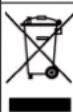
Do not throw batteries in the bin.
Description of the unit
Overview of the device
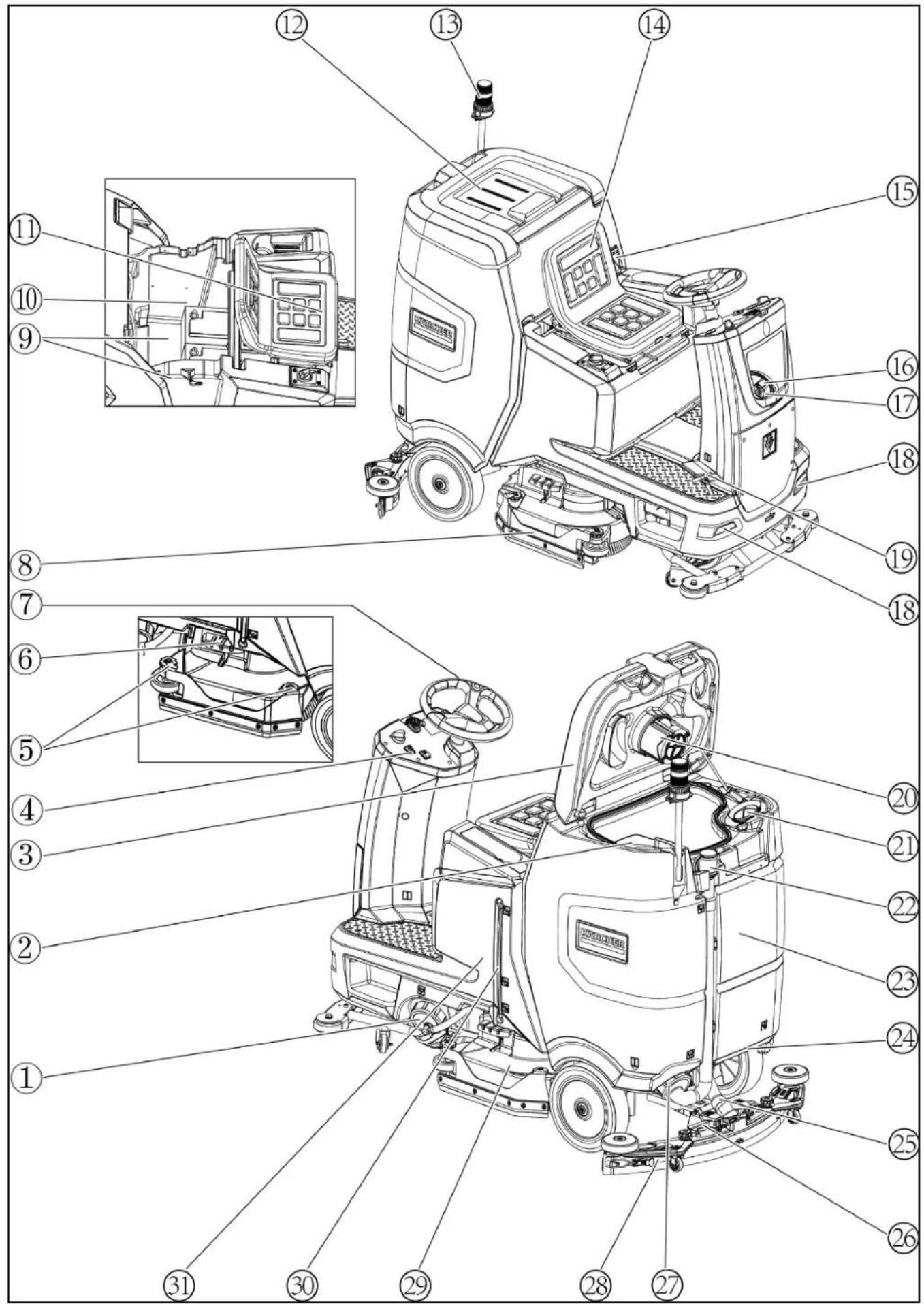
① Fresh water tank cap with fresh water filter ② Coarse dirt filter ③ Waste water tank cap ④ Control panel ⑤ Squeegee blade adjustment wheel (D cleaning head only) ⑥ Brush replacement pedal ⑦ Steering wheel ⑧ Side skirts ⑨*Battery ⑩ Type plate ⑪ Seat adjustment lever ⑫ Storage area for "Homebase Box" cleaning set ⑬*Warning light ⑭ Seat ⑮ Waste water tank latch ⑯ Fresh water tank filling hole ⑰ Hose holder ⑱ Daytime running light ⑲ Accelerator pedal ⑳ Float ㉑ Fluff filter ㉒ Waste water tank drain hose ㉓ Waste water tank ㉔* Mop holder ㉕ Suction hose ㉖ Suction bar clamping lever ㉗ Waste water tank cap ㉘ Suction bar ㉙ Cleaning head ㉚ Fresh water filling level indicator ㉛ Fresh water tank * optional
Colour coding
- Control elements for the cleaning process are yellow.
- Control elements for maintenance and servicing are light grey.
Control panel
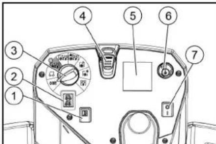
① Horn
② Travel direction switch
③ Program switch
④ Intelligent Key
⑤*Display
⑥ Info button
⑦ Safety switch
*Disturbances in the symbols on the display can be caused by the influence of electromagnetic devices such as mobile phones, but have no effect on the operating behavior.
Program switch
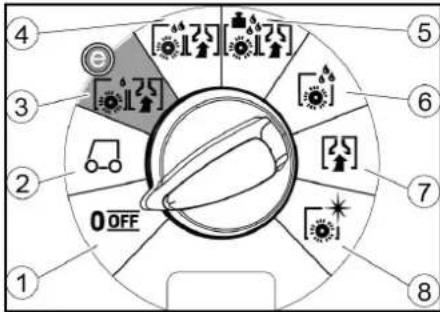
①OFF
Device is switched off.
②TRANSPORT MODE
Drive to the operating location.
③ ECO MODE
Clean the floor wet (with a reduced amount of water and a reduced brush speed) and vacuum up waste water (with reduced suction power).
④NORMAL MODE
Clean the floor wet and vacuum up waste water.
⑤HEAVY MODE
Clean the floor wet (with increased brush contact pressure) and vacuum up waste water.
⑥SCRUB MODE
Precleaning without vacuuming
Clean the floor wet and let the detergent act.
⑦ SUCTION MODE
Vacuum up the dirty waste.
⑧ POLISH MODE
Polish the floor at a high brush speed without applying liquid.
Symbols on the device

Fresh water tank drain opening
Waste water tank drain opening

Fresh water tank filling level (50%)

Lashing point

* Mop holder

Brush replacement

* optional
Installation
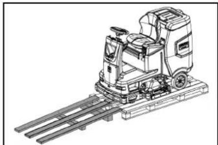
Unloading
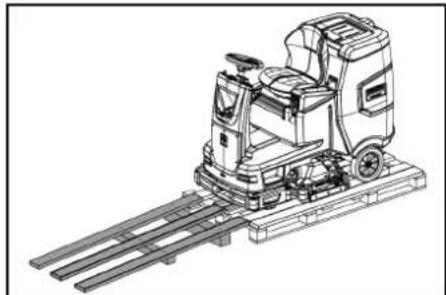
- Remove the packaging film.
- Remove the strap.
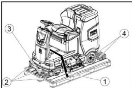
①Strap
②Board
③Block
④Beam
- Unscrew the block, squared timber and boards. The components to be unscrewed are marked in grey in the figure.
- Place a ramp in front of the pallet with the un-screwed boards and squared timber and fasten with chipboard screws.
- Unscrew the block, squared timber and boards. The components to be unscrewed are marked in grey in the figure.
- Place a ramp in front of the pallet with the unscrewed boards and squared timber and fasten with chipboard screws.
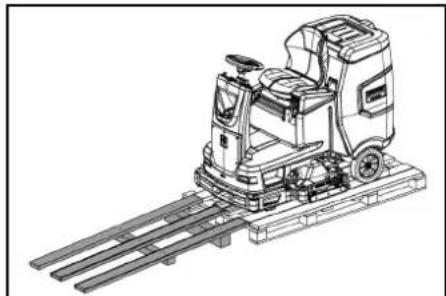
- Install the batteries if the device was delivered without batteries (see chapter "Before initial startup/batteries").
- Drive the device forward and off the pallet (see chapter "Operation / Driving").
Installing the brushes
- The installation of the brushes is described in the chapter "Maintenance work".
Installing the suction bar
- Pivot both clamping levers upwards.
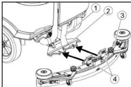
① Suction hose
② Suction bar suspension
③ Suction bar
④ Clamping lever
- Insert the suction bar in the suction bar mount.
- Pivot both clamping levers downwards.
Batteries
Installing and connecting batteries
CAUTION
Removing and installing the batteries
Unstable machine position
Ensure that the machine is positioned stably when removing and installing the batteries.
ATTENTION
Incorrect connection polarity
Destruction of the control electronics
Take care to ensure the correct polarity when connecting the batteries.
ATTENTION
Deep discharge
Risk of damage
Charge the batteries before starting the device.
- Drain the waste water.
- Unlock the waste water tank and pivot it up.
- Disconnect the seat switch and remove the seat.
- Place the battery in the device.
- Connect the device-side battery connector to the battery-side battery connector.
- Reset the seat and connect the seat switch.
- Pivot the waste water tank forwards and close it.
Removing the battery
△CAUTION
Removing and installing the batteries
Unstable machine position. Ensure that the machine is positioned stably when removing and installing the batteries. 1. Set the safety switch to "0". 2. Drain the waste water. 3. Unlock the waste water tank and pivot it up. 4. Pull out the battery plug.
- Disconnect the cable from the negative terminal of the battery.
- Disconnect the remaining cables from the battery.
- Remove the battery.
- Dispose of used batteries in accordance with statutory provisions.
Initial startup
Charging the battery
DANGER
Inappropriate use of the charger
Electric shock
Adhere to the mains voltage and fuse values specified on the device type plate.
Only use the charger in dry rooms with sufficient ventilation.
Flammable gases are generated when the battery is charged
Risk of explosion
Only charge the battery in a suitable room. The room must have a minimum volume depending on the battery type and an adequate air exchange rate with a minimum air flow (see "Recommended batteries").
CAUTION
Accumulation of dangerous gases under the tank during the charging process
Risk of explosion
Pivot the waste water tank upwards before charging low-maintenance batteries.
The average charging time is approx. 10-15 hours.
The device cannot be used during the charging process.
Note
The device has deep discharge protection, i.e. the brush motor and turbine are switched off automatically when the permitted minimum capacity level is reached.
- Drive the device directly to the charger and do not drive on slopes.
External charger
ATTENTION
Risk of damage due to unsuitable charger!
Do not connect the charger to the device-side battery connector.
Use only a charger suitable for the type of battery installed.
Battery Capacity Charger
4.039-352.7 170 Ah 6.654-436.0
- Unlock the waste water tank and pivot it up.
- Pull out the device-side battery connector.
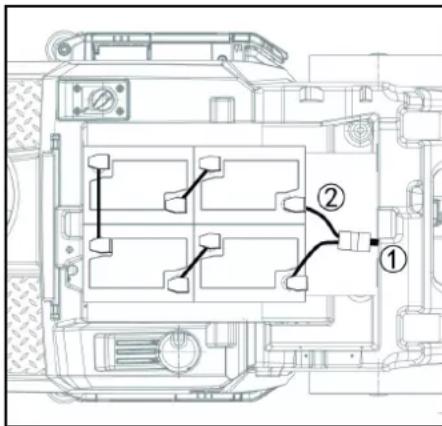
① Battery plug, device side ② Battery plug, battery side 3. Connect the battery-side battery connector to the charger. 4. Plug the mains plug of the charger into the socket. 5. Carry out the charging process in accordance with the operating instructions for the charger. 6. Connect the device-side battery connector to the battery-side battery connector. 7. Pivot the waste water tank forwards and then close it.
Low-maintenance batteries (wet batteries)
△DANGER
Refilling discharged batteries with water
Danger of acid burns from escaping acid, destruction of clothing. Wear safety goggles, protective clothing and protective gloves when handling the battery acid. Observe the applicable regulations.
Immediately rinse off any splashed acid from the skin or clothing using copious amounts of water.
ATTENTION
Using water with additives
Defective batteries, loss of warranty eligibility
Top up the batteries using only distilled or desalinated water (EN 50272-T3).
Do not use any foreign additives, so-called enhancing agents, because this will invalidate the warranty.
- Add distilled water one hour before the charging process comes to an end. Observe the correct acid level according to the battery label.
All cells must produce gas at the end of the charging process.
- Clean up any spilled water. To do this, proceed as described in the Care and maintenance chapter in the "Cleaning the batteries" section.
Operation
△DANGER
Falling objects
Risk of injury
Do not drive the device into areas where there is a possibility of the operating personnel being hit by falling objects.
ATTENTION
Risks during operation
Risk of injury
In the event of danger, set the safety switch to "0".
Pushing the device
To push the device, the brake must be unlocked.
△DANGER
Danger of accident
When the brake is unlocked, the function of the brake is permanently out of operation.
Be sure to remove the coins for unlocking immediately after the sliding process has ended.
- Swing the unlocking lever away from the wheel and hold it there.
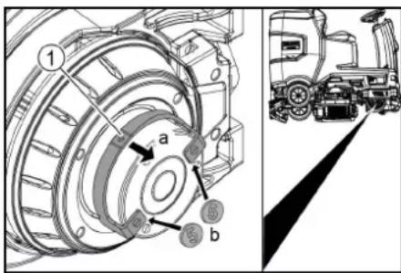
① Unlocking lever
- Insert a coin between the casing and the lever at both ends of the lever.
- Release the unlocking lever.
- Push the device.
- Remove both coins immediately after pushing.
Adjusting the seat
Adjusting the position
- Operate the seat adjustment lever and move the seat to the desired position.
- Release the seat adjustment lever and latch the seat into position.
Switching the device on
- Sit in the driver's seat.
- Insert the Intelligent Key.
- Set the safety switch to "1".
- Turn the program switch to the desired function.
- If one of the displays below appears on the display, take your foot off the accelerator pedal, set the safety switch to "0" and carry out the necessary maintenance work.
| Display Activity | |
| maintenance squeegee | Clean the suction bar. |
| maintenance brush head | Check the brushes for wear and clean them. |
| maintenance squeegee blade | Check the suction lips for wear and correct adjustment. |
| maintenance turbine filter | Clean the fluff filter. |
| maintenance fresh water filter | Clean the fresh water filter. |
- Press the Info button.
- Reset the counter for the corresponding maintenance (see "Grey Intelligent Key / Reset maintenance counter").
Note
If the counter is not reset, the maintenance display appears again each time the device is switched on.
Switching on the light
Daytime running light
The daytime running light is in operation when the device is switched on.
Checking the parking brake
△DANGER
Defective parking brake
Danger of accident
Before each operation, check the function of the parking brake on level ground.
- Switch the device on.
- Set the travel direction switch to "Forward".
- Set the program selector switch to "TRANSPORT MODE".
- Press the accelerator pedal lightly.
The brake must audibly unlock. The appliance must roll easily on a plane surface.
- Release the accelerator pedal.
The brake must be audibly engage.
If this is not the case, take the device out of operation and call Customer Service.
Driving
△DANGER
Lack of braking
Danger of accident
Before using the device, it is essential to check the function of the parking brake. Never use the device if the parking brake does not work.
△DANGER
Careless driving
Danger of tipping over
Only drive up and down gradients in the direction of travel and across the direction of travel 10%.
Do not turn up or down gradients.
Drive slowly in corners and on wet ground.
Only drive the device on stable ground.
Note
The travel direction can be changed while driving. This means that very dull spots can be polished by moving back and forth several times.
- Assume a seated position.
- Insert the Intelligent Key.
- Turn the safety switch to "1".
- Set the program selector switch to "TRANSPORT MODE".
- Set the direction of travel using the drive direction button on the control panel.
- Specify the travel speed by pressing the accelerator pedal.
- Release the accelerator pedal
The device stops.
The driving motor is switched off in the event of an overload. A fault message appears on the display. If the controller overheats, the affected power unit is switched off.
- Allow the device to cool down for at least 15 minutes.
- Set the program switch to "OFF", wait briefly and set to the desired program.
Filling with fresh water
Filling with fresh water
- Open the fresh water tank cap.
- Fill fresh water (max. 50 °C) to the lower edge of the filling nozzle.
Note: The fresh water hose can be clamped with the hose holder during filling.
- Close the fresh water tank lock.
Note: Please check the water level on a regular basis to avoid damages with cleaning without water and roller brush deck.
Filling with detergent
Notes on detergents
⚠ WARNING
Unsuitable detergents
Health risk, damage to the device
Use only recommended detergents. The operator carries all increased risks relating to operational safety and increased risk of accidents if using other detergents. Use only detergents free of chlorine, solvents, salt and hydrofluoric acid.
Adhere to the safety instructions stated on the detergent packaging.
Note
Do not use heavily foaming detergent.
Recommended detergents
| Application Detergent | |
| Maintenance cleaning of all water-resistant floors | RM 746RM 756RM 780 |
| Maintenance cleaning of polished hard surfaces (e.g. granite) | RM 755 es |
| Maintenance cleaning, intermediate cleaning and basic cleaning of industrial floors | RM 69 ASF |
| Maintenance cleaning and basic cleaning of fine stone tiles | RM 753 |
| Maintenance cleaning of tiles in sanitary areas | RM 751 |
| Coating removal on all alkaline-resistant floors (e.g. PVC) | RM 752 |
| Coating removal on linoleum floors | RM 754 |
Filling the detergent into the fresh water tank
- Fill the detergent into the fresh water tank. Note: The lid for the filling hole of the fresh water tank can be used to measure the detergent. It has a measuring scale marked on the inner side.
Adjusting parameters
- Set the program switch to the desired cleaning program.
- Turn the Info button until the desired parameter is displayed.
- Press the Info button. The adjusted value flashes.
- Set the desired value by turning the Info button.
- Confirm the changed setting by pressing the Info button or wait until the set value is automatically accepted after 10 seconds.
Yellow Intelligent Key
The yellow Intelligent Key authorizes functions that are required for the cleaning task.
The parameters for the various cleaning programs are preset in the device. Individual parameters can be changed depending on the authorization of the yellow Intelligent Key.
The display texts for parameter setting are largely self-explanatory.
"FACT" parameters (only available with R cleaning head):
- "Fine Clean": Low brush speed for removing grey film from fine stone.
- "Whisper Clean": Medium brush speed for maintenance cleaning with reduced noise level.
- "Power Clean": High brush speed for polishing, crystallizing and sweeping.
Adjusting the suction bar
Adjusting the inclination
The inclination must be adjusted so that the suction lips of the suction bar make even contact with the floor over the entire length of the suction bar.
- Park the device on a surface without a slope.
- Turn the program switch to the "Vacuum" position.
- Drive the device a small distance forwards.
- Read the spirit level.

① Screw
②Nut
③ Spirit level
- Unscrew the nut.
- Adjust the screw so that the spirit level indicator is between the two lines.
- Tighten the nut.
- To check the new setting, move the device forward again a short distance. Repeat the adjustment process if necessary.
- Turn the key-operated switch to "OFF".
Adjusting the height
The height adjustment affects the bending of the suction lips on contact with the floor.
Note
Standard setting: 3 washers above, 3 washers below the suction bar.
Uneven floor: 5 washers above, 1 washer below the suction bar.
Very smooth floor: 1 washer above, 5 washers below the suction bar.
- Unscrew the nuts.
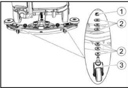
①Nut ② Washer ③ Spacer roller with holder 2. Place the desired number of washers between the suction bar and the spacer roller. 3. Fit the remaining unused washers above the spacer roller. 4. Screw on the nut and tighten. 5. Repeat the entire procedure at the second spacer roller.
Note
Set both spacer rollers to the same height.
Adjusting the squeegee blades
The squeegee blades only need to be adjusted on the D cleaning head.
- Adjust the squeegee blades by turning the setting wheel so that the squeegee blade touches the ground.
- Turn the adjustment wheel an additional 1 rotation down.
Cleaning
- Sit on the seat.
- Insert the Intelligent Key
- Set the safety switch to "1".
- Set the travel direction switch to forward travel.
- Set the program switch to the desired cleaning program.
- Determine the speed with the accelerator pedal.
- Determine the travel direction with the steering wheel.
- Drive over the surface to be cleaned.
Finishing operation
Finishing cleaning
- Set the program switch to drive.
- Continue moving for approximately 10 seconds. The residual water is vacuumed up.
- Turn the program switch to "OFF".
- Remove the Intelligent Key
- Charge the battery if necessary.
Draining the waste water
△WARNING
Improper disposal of waste water Environmental pollution
Observe the local waste water treatment regulations.
Note
When the waste water tank is full, the suction flow is interrupted by a float to prevent the waste water tank from overflowing. In this case, drain the waste water.
- Remove the waste water drain hose from the support and open the drain hose cover.
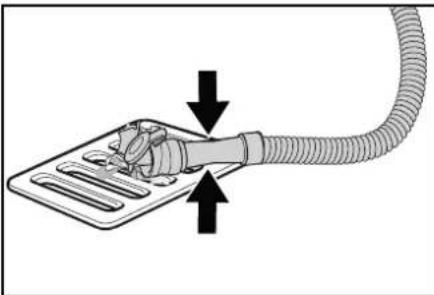
- Squeeze the end of the hose and lower it over the disposal facility.
- Adjust the strength of the waste water jet by squeezing the end of the hose.
- Rinse the waste water tank with clear water.
- Close the drain hose cover.
- Press the waste water hose into the support on the device.
Empty the coarse dirt container
- Lift the coarse dirt container and pull it out.
- Empty the coarse dirt container.
- Reinstall the coarse dirt container.
Draining fresh water
- Open the fresh water tank cap.
- Drain the fresh water.
- Clean the filter.
- Fit the fresh water tank cap.
Shutting down the unit
- Turn the key-operated switch to "OFF".
- Remove the Intelligent Key
- Secure the device against rolling away.
- Open the lid of the waste water tank and secure it with the support so that the waste water tank can dry out. To do this, swing the support down and position the lower end at the desired level when swinging down the cover.
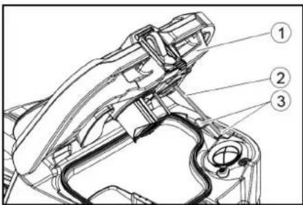
① Waste water tank cap
② Support
③ Level
- Charge the battery if necessary.
Grey Intelligent Key
The grey Intelligent Key grants the supervisory staff extended authorizations and setting options. 1. Insert the Intelligent Key. 2. Select the desired function by turning the info button.
Transport journey
- Set the program selector switch to "TRANSPORT MODE".
- Press the Info button. The following functions can be executed from the TRANSPORT MODE menu:
- Set maximum speed • Show operating hours counter
- Clearing the maintenance counter • Show software versions
- Adjust the R or D cleaning head
- Setting after-running times
- Setting the language • Key management • Activate factory setting
Maximum speed
The maximum speed can be limited in the "max speed" menu.
- Turn the info button until "max speed" is shown on the display.
- Press the Info button.
- Turn the info button until the desired maximum speed is displayed.
- Press the Info button.
Note
The working speed cannot exceed the maximum speed set.
Resetting the maintenance counter
If maintenance work shown in the display has been carried out, the corresponding maintenance counter must then be reset.
- Turn the Info button until "maintenance count." is displayed.
- Press the Info button.
The counter readings are displayed.
- Turn the info button until the counter to be cleared is highlighted.
- Press the Info button.
- Select "yes" by turning the Info button.
- Press the Info button. The counter is cleared.
Adjusting the cleaning head
- Turn the Info button until "brush head" is displayed in the menu.
- Press the Info button.
- Turn the Info button until the type of the built-in cleaning head is highlighted.
"Roll" = R cleaning head
"Disc" = D cleaning head
- Press the Info button.
After-running time
- Turn the Info button until the "delay times" menu item appears on the display.
- Press the Info button.
- Turn the Info button until the desired assembly is highlighted.
- Press the Info button.
- Turn the Info button until the desired after-running time is displayed.
- Press the Info button.
Setting the language
- Turn the info button until the "language" menu item appears on the display.
- Press the Info button.
- Turn the info button until the desired language is highlighted.
- Press the Info button.
Key management
The menu item "key menu" enables authorizations for yellow Intelligent Keys and the language of the display. 1. Insert the grey Intelligent Key. 2. Turn the info button until the "key menu" menu item appears on the display. 3. Press the Info button. 4. Remove the grey Intelligent Key and insert the yellow Intelligent Key to be personalized. 5. Select the menu item to be changed by turning the info button. 6. Press the Info button. 7. Select the setting of the menu item by turning the info button. 8. Confirm the setting by pressing the menu item. 9. Select the next menu item to be changed by turning the info button. 10. After all settings have been made, call up the "save" menu by turning the info button. 11. Press the Info button.
The authorizations are saved.
Factory setting
The factory settings for all cleaning parameters are restored.
- Turn the info button until the "factory settings" menu item is displayed.
- Press the Info button.
- Turn the Info button until "yes" is highlighted.
- Press the Info button.
Adjusting parameters for cleaning programs
All parameters for cleaning programs are retained until another setting is selected.
- Set the program switch to the desired cleaning program.
- Press the Info button. The first adjustable parameter is displayed.
- Press the Info button The adjusted value flashes
- Set the desired value by turning the Info button.
- Confirm the changed setting by pressing the Info button or wait until the set value is automatically accepted after 10 seconds.
- Select the next parameter by turning the Info button.
- After changing all desired parameters, turn the Info button until the "exit" menu item is displayed.
- Press the Info button.
The menu is exited.
Transport
△DANGER
Driving on slopes
Risk of injury
Observe the maximum permissible gradient when driving the device on slopes for loading and unloading purposes (see chapter "Technical data").
Drive slowly.
△CAUTION
Failure to observe the weight
Risk of injury and damage
Be aware of the weight of the device during transportation.
- With the D cleaning head installed, remove the disc brushes from the brush head.
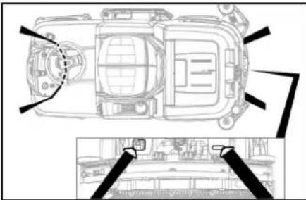
- When transporting in vehicles, secure the device against slipping and tipping over according to the applicable guidelines.
Storage
△CAUTION
Failure to observe the weight
Risk of injury and damage
Be aware of the weight of the device during storage.
ATTENTION
Frost
Destruction of the device through freezing water
Drain all water from the device.
Store the device in a frost-free location.
This device may only be stored indoors.
- Fully charge the batteries before storing them for a long period.
- Fully charge the batteries at least every month during storage.
Care and maintenance
DANGER
Inadvertently starting up device
Risk of injury, electric shock
Turn the program switch to the "OFF" position.
Remove the Intelligent Key prior to all work on the device.
Pull out the charger mains plug.
Unplug the battery connector.
Drain and dispose of the waste water and fresh water.
Maintenance intervals
Each time after use
ATTENTION
Improper cleaning
Risk of damage.
Do not spray the device with water.
Do not use aggressive cleaning agents.
A detailed description of the individual maintenance
work is provided in the chapter "Maintenance Work".
- Drain the waste water
- Rinse the waste water tank with clear water.
- Clean the coarse dirt filter.
- Only with R cleaning head: Remove the coarse dirt container and empty it.
- Clean the exterior of the device using a damp cloth, wetted with a mild washing lye.
- Check the suction lips, check for wear and replace if necessary.
- Clean the squeegee blades, check for wear and replace if necessary.
- Clean the brushes, check for wear and replace if necessary.
- Charge the battery.
- If the charging state of the battery is below 50%, charge the battery fully and without interruption.
- If the charging state of the battery is above 50%, only recharge the battery if the entire operating duration will be required when next used.
Weekly
- When used regularly, charge the battery fully and without interruption at least once a week.
Monthly
A detailed description of the individual maintenance work is provided in the chapter "Maintenance Work".
- If the device is temporarily shut down: Perform equalization charging of the battery.
- Check battery poles for oxidation, brush off if necessary. Make sure the connection cables are firmly in place.
- Clean the seals between the waste water tank and the cover, check for leaks and replace if necessary. Drain the fresh water tank and flush out deposits.
- Clean the fresh water filter.
- Check the acid density of the cells if the batteries are not maintenance-free.
- Only with R cleaning head: Clean the brush tunnel.
- Only with R cleaning head: Clean the water distribution strip on the cleaning head.
- For longer periods of disuse, shut down the device when the battery is fully charged. Fully charge the battery at least once a month.
Annually
● Have the prescribed inspection performed by Customer Service.
Safety inspection/maintenance contract
You can agree on regular safety inspections or close a maintenance contract with your dealer. Please seek advice on this.
Maintenance work
Turn over or replace the worn suction lips
The suction lips must be turned over or replaced when worn out. The suction lips can be turned 3 times until all 4 edges are worn. 1. Remove the suction bar. 2. Unscrew the star handles.
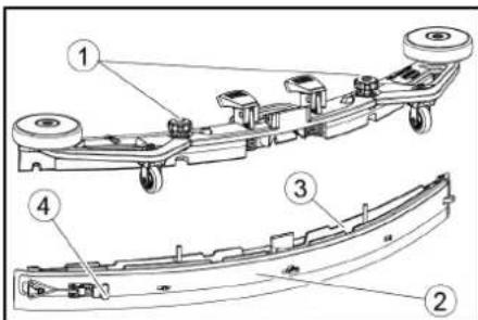
① Star grip ②Strap ③Inner part of the suction bar ④ Tension lock
- Pull out the inner part of the suction bar.
- Open the tension lock.
- Remove the strap.
- Release the suction lips from the inner part.
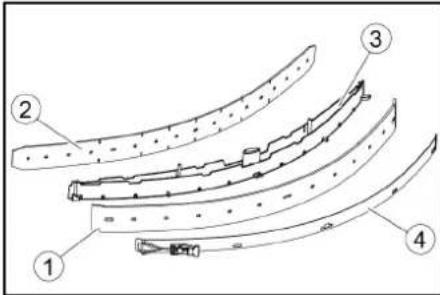
① Squeegee blade
② Support lip
③ Inner part of the suction bar
④ Strap
- Press the turned or new suction lips onto the knobs of the inner part of the suction bar.
- Attach the strap.
- Push the inner part of the suction bar into the upper part.
- Screw in and tighten the star handles.
Cleaning the coarse dirt filter
- Open the waste water tank cover.
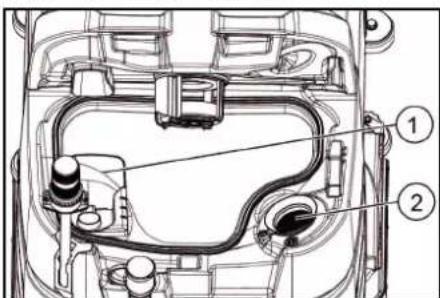
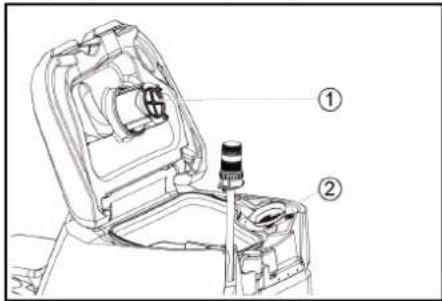
① Coarse dirt filter ② Fluff filter
- Pull the coarse dirt filter upwards and off.
- Rinse off the coarse dirt filter under running water.
- Reinsert the coarse dirt filter into the waste water tank.
Cleaning the float and fluff filter
- Open the waste water tank cover.
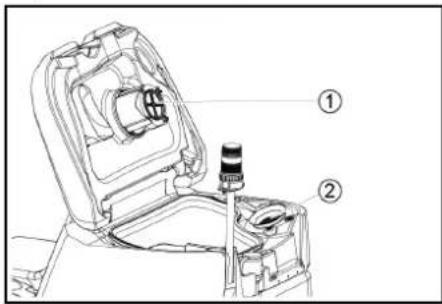
①Float ②Fluff filter 2. Rinse the float with clear water. 3. Remove and clean the fluff filter.
Replacing the disc brush
Note
Replace the disc brushes when the bristle length has reached 10 mm.
- Raise the cleaning head.
- Push the brush replacement pedal down.
- Pull the disc brush sideways and out from underneath the cleaning head.
- Hold the new disc brush under the cleaning head, then press upwards and latch it into position.
Replacing the roller brushes
Note
Replace the roller brushes when the bristle length has reached 10 mm.
- Raise the cleaning head.
- Pull out the brush replacement handle.
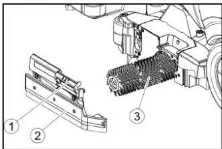
① Brush replacement handle ② Bearing cover with squeegee blade
③ Roller brush
- Remove the bearing cover including the squeegee blade.
- Pull out the roller brush.
- Fit the new roller brush and centre it on the driver.
① Driver
② Mounting mandrel
- Install the bearing cover with the squeegee blade.
Note
Make sure the roller brush sits on the mounting mandrel and not underneath.
- Pivot the brush replacement handle upwards and latch it into place.
- Repeat the entire procedure at the other side.
Cleaning the fresh water filter
- Drain the fresh water (see chapter "Draining fresh water").
- Unscrew the fresh water tank cap.
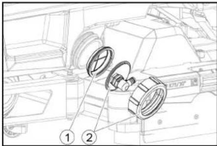
① Fresh water filter
② Fresh water tank lock
- Pull out the fresh water filter and rinse with clean water.
- Insert the fresh water filter.
- Fit the fresh water tank lock. Note: Take care to ensure that the hose connection in the fresh water tank cap is positioned at the lowest point in the tank after screwing the cap in place.
Cleaning the water distribution strip
- Press the latch in the direction of the arrow and hold it there.

- Pivot the water distribution strip forward.
- Pull out the water distribution strip lengthways.
- Clean the water distribution strip.
- Fit the water distribution strip back into the cleaning head and snap the lock into place.
Cleaning batteries
- Wear safety goggles, protective clothing and protective gloves.
- Keep the battery cell plugs closed.
- Remove the batteries.
- Only clean the plastic parts of the batteries and the battery compartment with water or water-soaked cleaning cloths without additives.
- Dry the surfaces after cleaning.
- Reinstall the batteries.
Resetting the maintenance counter
If maintenance work shown in the display has been carried out, the corresponding maintenance counter must then be reset.
Note
Resetting the maintenance counters is described in the chapter "Grey Intelligent Key".
Troubleshooting guide
△DANGER
The device can start unintentionally
People working on the device can be injured.
Remove the Intelligent Key prior to all work on the device.
Before carrying out any work, pull the mains plug of the internal charger out of the socket.
Disconnect the battery connector before performing any work.
- Drain the waste water.
- Drain the remaining fresh water.
Note
If the malfunction cannot be remedied with the following instructions, contact Customer Service.
Malfunctions with information shown on the display
If the displayed malfunction is not in the following list, do the following:
- Turn the key-operated switch to "OFF".
- Wait 10 seconds.
- Set the program switch to the previous function.
- If the malfunction recurs, call Customer Service.
| Malfunction Rectification | |
| fresh water empty 1. Refill the fresh water tank | |
| water valve blocked 1. Set the program | me switch to "OFF".2. Wait 10 seconds.3. Set the program switch to the desired program. |
| overload brush head 1. Reduce the contact pressure of the brushes. | |
| blocked main brush | 1. Check if the brushes are blocked by a foreign body and remove the foreign body if necessary.2. Set the programme switch to "OFF".3. Wait 10 seconds.4. Set the program switch to the desired program. |
| overload side brush 1. Reduce the contact pressure of the side scrubbing deck brush. | |
| blocked drive motor 1. Check the wheels for blockage, remove foreign objects.2. Set the programme switch to "OFF".3. If the engine has overheated, let it cool down for at least 15 minutes, otherwise wait 10 seconds.4. Set the program switch to the desired program. | |
| battery low 1. Set the program selector switch to TRANSPORT MODE.2. Drive the device directly to the charger (or with an internal charger to the socket). Avoid gradients.3. Charge the battery. | |
| battery empty 1. Set the program selector switch to TRANSPORT MODE.2. Drive the device by the shortest route to the charger (or to the socket in the case of an internal charger). Avoid gradients.3. Charge the battery. | |
| seat switch open | 1. Relieve the driver's seat briefly so that the control can check the function of the seat contact switch. |
| switch on! | 1. Set the safety switch to "1". |
| restart machine | 1. Set the programme switch to "OFF".2. Wait 10 seconds.3. Set the program switch to the desired program. |
| release throttle | 1. Release the accelerator pedal. |
Malfunctions without information shown on the display
| Malfunction Rectification | |
| The device cannot be started 1. Sit in the driver's seat.2. Take your foot off the accelerator before switching on the safety switch.3. Turn the safety switch to "1".4. Check the battery and charge if necessary.5. Set the programme switch to "OFF".6. Wait 10 seconds.7. Set the program switch to the desired program.8. If possible, only drive the device on level ground.9. Check the parking brake if necessary.If the fault still occurs, call Customer Service. | |
| The device is no longer running, display shows "battery empty" | 1. Set the programme switch to "OFF".2. Wait 10 seconds.3. Set the program selector switch to "TRANSPORT MODE".4. Drive to the charging station.5. If the device still does not run, charge the battery on site or unlock the brake (see "Operation/pushing the device") and push the device to the charging station. |
| The device moves unevenly (jerks) when starting and stopping. | 1. Unlock the brake lock (see "Operation/pushing the device"). |
| The water volume is insufficient | 1. Check the fresh water filling level, if necessary fill the tank completely so that the air is pressed out.2. Remove and clean the fresh water filter.3. Insert the filter and screw on the cap.4. Check the hoses for clogging and clean if necessary. |
| The fresh water display shows the wrong filling level after emptying the tank manually. | 1. Use the device. During operation, the hose system will vent and the filling level display will correct itself. |
| The bar of the filling level display is flashing, "fresh water empty" display | 1. Refill the fresh water tank. |
| The suction performance is too low | 1. Clean the seals between the waste water tank and the cover, check for leaks and replace if necessary.2. Check the fluff filter for soiling and clean if necessary.3. Clean the suction lips at the suction bar, turn over or replace if necessary.4. Close the lid on the waste water drain hose.5. Close the cover of the waste water tank rinsing system.6. Check the suction hose for clogging and clean if necessary.7. Check the suction hose for leaks and replace if necessary.8. Check the adjustment of the suction bar. |
| The cleaning results are unsatisfactory | 1. Set the appropriate cleaning program for the cleaning task.2. Use suitable brushes for the cleaning task.3. Use a suitable detergent for the cleaning task.4. Reduce the driving speed.5. Adjust the contact pressure.6. Adjust the squeegee blades.7. Check the brushes for wear and replace if necessary.8. Check the water output. |
| The brushes do not rotate 1. Reduce the contact pressure.2. Check if the brushes are blocked by a foreign body and remove the foreign body if necessary.3. If the motor is overloaded, let the motor cool down.4. Set the programme switch to "OFF".5. Wait 10 seconds.6. Set the program switch to the desired program.7. Check that the plug of the device is plugged into the cleaning head. | |
| The device does not brake | 1. Undo the brake lock (see "Operation / Pushing the device"). |
| The waste water drain hose is clogged | 1. Open the dosing unit cover at the drain hose.2. Pull the suction hose off the suction bar and close it by hand.3. Set the programme switch to "Vacuum".The blockage is sucked out of the drain hose into the waste water tank. |
Warranty
The warranty conditions issued by our sales company responsible apply in all countries. We shall remedy possible malfunctions on your device within the warranty period free of cost, provided that a material or manufacturing defect is the cause. In a warranty case, please
contact your dealer or our customer service.
Contact your dealer (with the purchase receipt) or the next authorized customer service site. (See overleaf for the address)
Accessories
Cleaning head with roller brush accessories A: Packaging unit, B: Quantity required by the device
| Description R 75 | Part no. | Description A B | ||
| Roller brush, red (medium, standard) | 4.035-605.0 | For maintenance cleaning of heavily soiled floors. | 1 | 2 |
| Roller brush, white (soft) | 6.907-771.0 | For polishing and maintenance cleaning of sensitive floors. | 1 | 2 |
| Roller brush, orange (high / low) | 6.907-730.0 | For scrubbing structural floors (safety tiles, etc.). | 1 | 2 |
| Roller brush, green (hard) | 6.907-731.0 | For basic cleaning of heavily soiled floors and for coating removal (e.g. waxes, acrylates). | 1 | 2 |
| Roller brush, black (very hard) | 6.907-732.0 | 1 | 2 | |
| Microfiber roller | 4.114-007.0 | For maintenance cleaning of smooth floors. | 1 | 2 |
| Pad roller shaft | 4.762-627.0 | For holding roller pads. | 1 | 2 |
| Roller pad, yellow (soft) | 6.369-454.0 | For polishing floors | 20 | 96; 106 |
| Roller pad, red (medium) | 6.369-456.0 | For cleaning lightly soiled floors. | 20 | 96; 106 |
| Roller pad, green (hard) | 6.369-455.0 | For cleaning normal to heavily soiled floors. | 20 | 96; 106 |
Cleaning head with disc brushes accessories
A: Packaging unit, B: Quantity required by the device
| Description | D 75 Part no. | Description | A | B |
| Disc brush, natural colour (soft) | 4.905-020.0 | For polishing floors. | 1 | 2 |
| Disc brush, white | 4.905-019.0 | For polishing and maintenance cleaning of sensitive floors. | 1 | 2 |
| Description D 75 | Part no. | Description | A | B |
| Disc brush, red (medium, standard) | 4.905-018.0 | For cleaning lightly soiled or sensitive floors. | 1 | 2 |
| Disc brush, black (hard) 4.905-021.0 For cleaning heavily soiled | floors. 1 2 | |||
| Fine diamond pad, green 6.371-236.0 For refreshing lime-containing coverings and epoxy resin-coated floors. 5 2 | ||||
| Coarse diamond pad, white 6.371-252.0 5 | 2 | |||
| Medium diamond pad, yellow 6.371-253.0 5 | 2 | |||
| Pad drive board 4.762-447.0 For holding pads. 1 2 | ||||
Suction bar accessories
A: Packaging unit, B: Quantity required by the device
| Description | Part no. | Description | A | B |
| Suction lip set, front PU (red), rear Linatex | 4.039-366.0 | Standard | Pair | 1 pair |
| Suction lip set, Linatex | 4.039-356.0 | Tear-proof | Pair | 1 pair |
| PU suction lip set | 4.039-357.0 | Oil-proof | Pair | 1 pair |
Technical data
| B 110 Classic D 75 | B 110 Classic R 75 | |||
| General | ||||
| Driving / cleaning speed | km/h | 6 | 6 | |
| Transport speed km/h | 6 | 6 | ||
| Travel speed, backwards | km/h | 4 | 4 | |
| Theoretical surface performance | m2/h | 4500 | 4500 | |
| Practical surface performance | m2/h | 3150 | 3150 | |
| Fresh water tank capacity | I 130 | 130 | ||
| Waste water tank capacity | I | 110 | 110 | |
| Coarse dirt container capacity | I - | 1.8 | ||
| Water dosage | l/min | 0...8 | 0...8 | |
| Load per unit area (with driver and full fresh water tank) | ||||
| Surface pressure | N/mm2 | 0.64 | 0.64 | |
| Load per unit area (weight / parking area) | kg/m2 | 563 | 563 | |
| Dimensions | ||||
| Length | mm | 1660 | 1660 | |
| Width | mm | 1035 | 1035 | |
| Wide suction bar | mm | 1000 | 1000 | |
| Height | mm | 1480 | 1480 | |
| Working width | mm | 750 | 750 | |
| Packaging dimensions lxwxh | mm | 1715x1140x1625 | 1715x1140x1625 | |
| Turning circle | mm | 1750 | 1750 | |
| Battery compartment dimensions lxwxh | mm | 420x630x400 | 420x630x400 | |
| Tyres | ||||
| Front wheel, width | mm | 90 | 90 | |
| Front wheel, diameter | mm | 250 | 250 | |
| Rear wheel, width | mm | 75 | 75 | |
| Rear wheel, diameter | mm | 290 | 290 | |
| Weight | ||||
| Approved total weight | kg | 720 | 720 | |
| Net weight (transport weight) | kg | 380 | 380 | |
| Typical operating weight | kg | 590 | 590 | |
| Brush contact force, max. | N (kg) | 736 (75) | 736 (75) | |
| Brush contact pressure, max. | N / m2(g/cm2) | 510 (500) 510 (500) | ||
| Device performance data | ||||
| Nominal voltage | V | 24 | 24 | |
| Battery capacity* (Factory installed, if Bp Pack version) | Ah (5 h) | 170 | 170 | |
| Mean power input | W | 2350 | 2350 | |
| Nominal power | W | 2500 | 2500 | |
| Driving motor power | W | 600 | 600 | |
| Suction turbine power | W | 600 | 600 | |
| Brush drive power | W | 2 x 600 | 2 x 600 | |
| Degree of protection | IPX3 | IPX3 | ||
| Vacuuming | ||||
| Suction performance, air quantity | l/s | ~25 | ~25 | |
| Vacuum (max.) | kPa (mbar) | ~17 (~170) | ~17 (~170) | |
| Vacuum (in operation) | kPa (mbar) | ~5 (~50) | ~5 (~50) | |
| Cleaning brushes | ||||
| Brush diameter | mm | 410 | 100 | |
| Brush length | mm | - | 705 | |
| Brush speed | 1/min | 180 | 1200 | |
| External charger | ||||
| Nominal voltage | V | 230 | 230 | |
| Frequency | Hz | 50-60 | 50-60 | |
Charging current A 50 50
Weight kg 4.5 4.5
Ambient conditions Permissible temperature range °C 5...40 5...40 Water temperature max. °C 50 50
| Relative humidity | % | 20...90 | 20...90 |
| Incline | |||
| Max. working area slope | % | 10 10 | |
| Short distance incline (max. 10 m) transport, loading | % | 22 22 | |
| Determined values in acc. with EN 60335-2-72 | |||
| Hand-arm vibration value | m/s2 | <2.5 | <2.5 |
| Seat vibration value | m/s2 | <2.5 | <2.5 |
| Uncertainty K | dB(A) | 0.2 0.2 | |
| Sound level LpA eco operation | dB(A) | 59.2 | 59.2 |
| Sound level LpA normal operation | dB(A) | 63.6 | 63.6 |
| Uncertainty KpA | dB(A) | 1.6 1.6 | |
| Sound power level LWA + Uncertainty KWA eco operation | dB(A) | 74.1 | 74.1 |
| Sound power level LWA + Uncertainty KWA normal operation | dB(A) | 78.7 | 78.7 |
Subject to technical modifications.
Declaration of Conformity
EU Declaration of Conformity
We hereby declare that the machine described below complies with the relevant basic safety and health requirements in the EU Directives, both in its basic design and construction as well as in the version placed in circulation by us. This declaration is invalidated by any changes made to the machine that are not approved by us.
Product: Floor cleaner
Type: 1.161-xxx
Currently applicable EU Directives
2006/42/EC (+2009/127/EC)
2014/30/EU
2014/53/EU (TCU)
National standards used
The signatories act on behalf of and with the authority of the company management.
Chairman of the Board of Management
Director Regulatory Affairs & Certification
Documentation supervisor:
S. Reiser
Alfred Kärcher SE & Co. KG
Alfred-Kärcher-Str. 28 - 40
71364 Winnenden (Germany)
Ph.: +49 7195 14-0
Fax: +49 7195 14-2212
Winnenden, /09/01
Declaration of Conformity (UK)
We hereby declare that the product described below complies with the relevant provisions of the following UK Regulations, both in its basic design and construction as well as in the version put into circulation by us. This declaration shall cease to be valid if the product is modified without our prior approval.
Product: Floor cleaner
Type: 1.161-xxx
Currently applicable UK Regulations
S.I. 2008/1597 (as amended)
S.I. 2016/1091 (as amended)
S.I. 2017/1206 (as amended) (TCU)
National standards used
The signatories act on behalf of and with the authority of the company management.
H. Jenner Chairman of the Board of Management
S. Reiser Director Regulatory Affairs & Certification
Documentation supervisor:
S. Reiser
Alfred Kärcher SE & Co. KG
Alfred-Kärcher-Str. 28 - 40
71364 Winnenden (Germany)
Ph.: +49 7195 14-0
Fax: +49 7195 14-2212
Winnenden, /09/01
Contents
① Horn
① Clamping strap
② Board
③ Wedge
4 Wood
① Screw
② Nut
③ Spirit level
① Nut
② Washer
Storage
△ PRECAUTION
2006/42/EC (+2009/127/EC)
2014/30/EU
2014/53/EU (TCU)
H. Jenner Chairman of the Board of Management
S. Reiser Director Regulatory Affairs & Certification
71364 Winnenden (Germany)
1 Horn
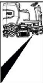
① Release lever
① Nut ② Washer
Storage
⚠CAUTION
Failure to observe the weight
①Coarse dirt filter ②Lint filter
①Float
②Lint filter
H. Jenner Chairman of the Board of Management
S. Reiser Director Regulatory Affairs & Certification
71364 Winnenden (Germany)
Tel.: +49 7195 14-0
Fax: +49 7195 14-2212
Winnenden, 01/09/
①Horn
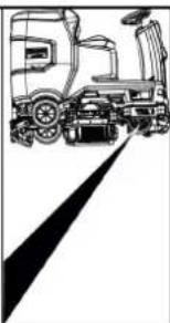
①Screw
②Nut
③Water level
①Nut
②Washer
Storage
△CAUTION
①Float
②Lint filter
2006/42/EC (+2009/127/EC)
2014/30/EU
2014/53/EU (TCU)
H. Jenner Chairman of the Board of Management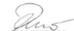
S. Reiser Director Regulatory Affairs & Certification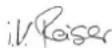
71364 Winnenden (Germany)
Tel.: +49 7195 14-0
Fax: +49 7195 14-2212
Index
① Horn
② Direction switch
③ Program switch
④ Smart key
⑤ Display
⑥ Info button
① Clamp
② Board
③ Wedge
④ Wedge beam
① Nut
② Washer
③ Spacer roller with support
Storage
△CAUTION
2006/42/EC (+2009/127/EC)
2014/30/EU
2014/53/EU (TCU)
H. Jenner Chairman of the Board of Management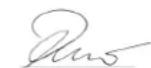
S. Reiser Director Regulatory Affairs & Certification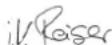
① Horn
① Tension strap
② Board
③ Block
④ Edge timber
① Suction hose
② Suction beam suspension
③ Suction beam
④ Clamping handle
① Release handle
1 Screw ② Nut
③ Spirit level
① Nut
② Washer
① Dirty water tank lid
② Support
③ Level
- Charge the battery if necessary.
Storage
⚠ CAUTION
① Brush change handle
① Fresh water filter
② Fresh water tank shut-off
H. Jenner Chairman of the Board of Management
S. Reiser Director Regulatory Affairs & Certification
71364 Winnenden (Germany)
Tel.: +49 7195 14-0
Fax: +49 7195 14-2212
Contents
General warnings 72
Function.... 72
①Horn
①Tension band ②Board
③Wedge
④ Edge timber
①Vacuum hose
①Unlocking lever
①Bolt ② Nut ③ Spirit level
①Somun
②Pul
③Tutuculu ara silindir
Depolama
TEDBIR

Şamandıra

oz süzgeci
①Temiz su filtresi
2006/42/AT (+2009/127/AT)
2014/30/AB
2014/53/EU (TCU)
H. Jenner Chairman of the Board of Management
S. Reiser Director Regulatory Affairs & Certification
mation blir heta under drift.
①Horn
① Strapping band
② Board
③ Block
④ Wooden beam
① Suction hose
② Suction beam bracket
③ Suction beam
④ Clamping lever
① Battery contact, unit side
② Battery contact, battery side
① Release lever
① Screw
② Nut
③ Spirit level
Storage
⚠ CAUTION
1 Coarse dirt filter
② Lint filter
H. Jenner Chairman of the Board of Management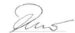
S. Reiser Director Regulatory Affairs & Certification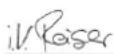
D-71364 Winnenden (Germany)
Tel: +49 7195 14-0
Fax: +49 7195 14-2212
Winnenden, 01.09.
Contents
General instructions 92
Operation.... 92
① Acoustic signal
② Direction switch
③ Program switch
④ Intelligent Key
⑤ Display
⑥ Information button
⑦ Safety switch
① Attachment strap
② Board
③ Beam
④ Support wood
① Hose
② Hose beam suspension
③ Hose beam
④ Tension lever
① Release lever
① Screw
② Nut
③ Water level
① Nut
② Washer
Storage
△WARNING
① Coarse dirt strainer
② Lint filter
H. Jenner Chairman of the Board of Management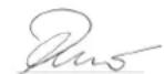
S. Reiser Director Regulatory Affairs & Certification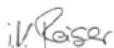
71364 Winnenden (Germany)
Tel.: +49 7195 14-0
① Horn
① Strips
② Board
③ Block
④ Square tube
① Suction hose ② Suction beam suspension ③ Suction boom ④ Locking arm 2. Insert the suction boom into the suction boom suspension. 3. Push both interlocks down.
Batteries
① Battery plug, machine side
① Unlock the lever
① Screw ② Nut ③ Water
① Nut ② Washer ③ Spacer wheel with holder 2. Place the desired number of washers between the suction boom and the spacer roller. 3. Place the remaining washers on top of the spacer wheel. 4. Screw on the nuts and tighten them. 5. Repeat the procedure on the other spacer wheel.
Note
① Dirty water tank cover ② Support ③ Step 5. Charge the battery if necessary.
Storage
△CAUTION
① Star handle ② Tension strap ③ Inner part of suction boom ④ Tension lock 3. Pull out the inner part of the suction boom. 4. Open the tension lock. 5. Remove the tension strap. 6. Detach the suction blades from the inner part.
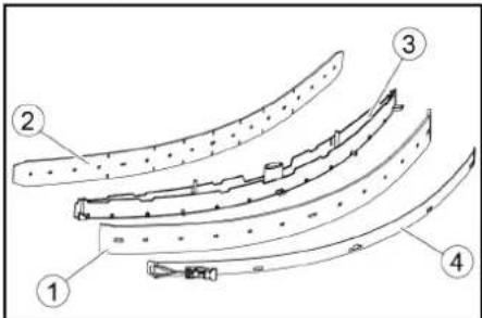
① Squeegee blade
② Support blade
③ Inner part of suction boom
④ Tension strap
- Press the turned or new suction pads onto the studs on the inner part of the suction boom.
- Mount the tension strap.
- Slide the inner part of the suction boom into the upper part.
- Screw in the star grips and tighten them.
Cleaning the coarse dirt filter
① Coarse dirt filter
② Fine filter
① Handle for brush change ② Bearing cover with wiper blade ③ Brush roller
① Clean water filter ② Clean water tank lid
- Remove the clean water filter and rinse it with clean water.
- Insert the clean water filter.
- Screw on the clean water tank lid. Note: Ensure that the hose connection in the clean water tank lid is at the lowest point when screwed on.
2006/42/EC (+2009/127/EC)
2014/30/EU
2014/53/EU (TCU)
Chairman of the Board of Management
S. Reiser Director Regulatory Affairs & Certification
71364 Winnenden (Germany)
Tel.: +49 7195 14-0
① Horn
① Clamp
② Board
③ Block
④ Square timber
① Suction hose
② Suction beam suspension
③ Suction beam
④ Clamping handle
① Battery compartment, inside the machine ② Battery compartment, battery side
Hazardous situation during operation
① Safety handle
① Screw
② Nut
③ Spirit level
① Nut
② Washer
Storage
△ CAUTION
① Star knob
② Clamping strap
① Striking-off strip
② Support lip
① Coarse filter
② Fine filter
① Pump ② Filter cartridge
① Clean water tank filter
2006/42/EC (+2009/127/EC)
2014/30/EU
2014/53/EU (TCU)
H. Jenner Chairman of the Board of Management
S. Reiser Director Regulatory Affairs & Certification
71364 Winnenden (Germany)
Tel.: +49 7195 14-0
Fax: +49 7195 14-2212
Winnenden, /09/01
Table of contents
General instructions.... 122
Function 122
① Signal
② Direction switch
③ Program switch
④ Smart key
⑤* Display
⑥ Info button
⑦ Safety switch
① Tension strap
② Table
③ Block
④ Wooden beam
Mounting the imitation board
① Hose
② Hanging bracket for imitation board
③Imitala
④ Locking lever
- Place the imitala in the hanging holder.
- Turn both locking levers down.
Batteries
①Battery connector, device side
①Release lever
①Bolt
②Nut
③ Spirit level
①Nut
②Washer
①Dirty water tank cover
②Tugi
③Aste
Ladustamine
△ETTEVAATUS
Kaalu eiramine
①Ujuk
② Ebemefilter
①Puhtaveefilter ②Puhtaveepaagi sulgur
2006/42/EÜ (+2009/127/EÜ)
2014/30/EL
2014/53/EL (TCU)
H. Jenner Chairman of the Board of Management
S. Reiser Director Regulatory Affairs & Certification
71364 Winnenden (Germany)
Tel: +49 7195 14-0
①Taure
①Spriegotājsiksna
②Dēlis
③ Klucis
4 Brusa
①Atblokëšanas svira
①Uzgrieznis
②Paplāksne
Uzglabāšana
⚠UZMANĪBU
Svara neievērošana
①Pludinš
②Pūku siets
- Noskalojiet pludinu ar tīruūdeni.
- Iznemiet un notīriet pūku filtru.
Wheel replacement
Instructions
① Fresh water filter
Chairman of the Board of Management
S. Reiser
Director Regulatory Affairs & Certification
① Acoustic signal
① Tensioning belt ② Board
③ Pad
④ Wooden dowel
① Suction hose
① Unlocking lever
① Nut ② Washer
③ Gap adjustment roller with holder
① Dirty water tank lid
② Atrama
③ Režimas
- If necessary, insert the battery.
Storage
CAUTION
① Brush replacement handle ② Bearing cover with cleaning scraper ③ Brush shaft
① Clean water filter ② Clean water tank cover
H. Jenner Chairman of the Board of Management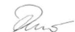
S. Reiser Director Regulatory Affairs & Certification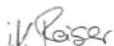
① Horn
① Clamping strap
② Board
③ Block
④ Edge beam
① Suction hose
①Screw
②Nut
③Water level
①Nut
②Washer
Storage
△CAUTION
①Star handle
②Strap
①Squeegee strip
①Platform
②Lint filter
①Clean water filter
2006/42/EC (+2009/127/EC)
2014/30/EU
2014/53/EU (TCU)
H. Jenner Chairman of the Board of Management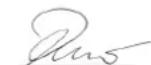
S. Reiser Director Regulatory Affairs & Certification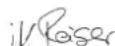
71364 Winnenden (Germany)
Tel.: +49 7195 14-0
① Fastening strap
② Board
③ Wooden block
④ Edge strip
① Screw
② Nut
③ Spirit level
① Nut
② Washer
Storage
△WARNING
①Coarse dirt filter
②Lint filter
①Float ②Lint filter
①Fresh water filter
O
H. Jenner Chairman of the Board of Management
S. Reiser Director Regulatory Affairs & Certification
①Horn
①Strap
②Board
③Block
④Wooden block
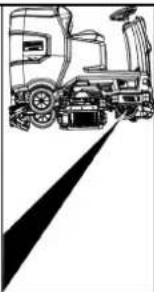
①Release lever
①Screw ②Nut ③Water level
① Nut ② Washer
Storage
⚠ WARNING
① Coarse dirt strainer
② Fiber screen
① Float
② Fiber filter
① Fresh water filter
2006/42/EC (+2009/127/EC)
2014/30/EU
2014/53/EU (TCU)
H. Jenner Chairman of the Board of Management
S. Reiser Director Regulatory Affairs & Certification
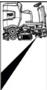
① Fresh water tank cap with fresh water filter ② Coarse dirt filter ③ Waste water tank cap ④ Control panel ⑤ Wheel for adjusting the suction bar (only cleaning head D) ⑥ Pedal for changing the brush ⑦ Steering wheel ⑧ Side panels ⑨ Battery ⑩ Type plate ⑪ Seat adjustment lever ⑫ Storage space for the “Homebase Box” cleaning set ⑬* Warning light ⑭ Seat ⑮ Waste water tank latch ⑯ Fresh water tank filler opening ⑰ Hose holder ⑱ Daytime running light ⑲ Gas pedal ⑳ Float ㉑ Fiber filter ㉒ Waste water tank drain hose ㉓ Waste water tank ㉔* Mop holder ㉕ Suction hose ㉖ Suction bar clamping lever ㉗ Waste water tank cap ㉘ Suction bar ㉙ Cleaning head ㉚ Fresh water fill level indicator ㉛ Fresh water tank
* optional
Part designation
① Horn
② Direction switch
③ Program switch
④ Intelligent key
⑤ Display
⑥ Info button
① Clamping strap
② Plate
③ Bar
④ Wooden block
① Suction hose ② Suction bar mounting ③ Suction bar ④ Clamping lever 2. Insert the suction bar into the suction bar mounting. 3. Turn both clamping levers downwards.
Batteries
① Battery connector, device side ② Battery connector, battery side 3. Connect the battery connector on the battery side to the charger. 4. Plug the charger's electrical plug into the socket. 5. Perform the charging process according to the charger's operating instructions. 6. Connect the battery connector on the device side to the battery connector on the battery side. 7. Tilt the waste water tank forward and then close it.
Maintenance-free batteries (wet batteries)
DANGER
①Unlocking lever
- Insert a coin between the cover and the lever at both ends of the lever.
- Release the unlocking lever.
- Move the device.
- Immediately after the moving process, remove both coins again.
Seat adjustment
Position adjustment
- Press the seat adjustment lever and slide the seat to the desired position.
- Release the seat adjustment lever and lock the seat.
Turning on the device
- Sit on the driver's seat.
- Insert the smart key.
- Switch the safety switch to position "1".
- Turn the program switch to the desired function.
- If any of the displays shown below appear on the screen, take your foot off the gas pedal, switch the safety switch to the "0" position, and perform the necessary maintenance work.
| Displej Činnost' | |
| maintenance squeegee | Vyčistite saciu lištu. |
| maintenance brush head | Skontrolujte opotrebovanie kief a vyčistite ich. |
| maintenance squeegee blade | Skontrolujte opotrebovanie a na-stavenie odsávacích stierok. |
| maintenance turbine filter | Očistite filter na žmolky. |
| maintenance fresh water filter | Vyčistite filter na čistú vodu. |
① Screw ② Nut ③ Spirit level
① Nut
② Washer
Storage
⚠ WARNING
① Star handle
② Clamping strap
1 Squeegee
② Protective rubber
① Coarse dirt filter ② Lint filter 2. Pull the coarse dirt filter upwards. 3. Clean the coarse dirt filter under running water. 4. Insert the coarse dirt filter into the dirty water tank. 1. Open the cover of the waste water tank.
2006/42/EC (+2009/127/EC)
2014/30/EU
2014/53/EU (TCU)
H. Jenner Chairman of the Board of Management
S. Reiser Director Regulatory Affairs & Certification
71364 Winnenden (Germany)
Tel.: +49 7195 14-0
Fax: +49 7195 14-2212
Winnenden, 01.09.
Table of Contents
General instructions.... 192
Function.... 192
Intended use.... 192
Environmental protection 192
Accessories and spare parts 192
Scope of delivery.... 192
Safety instructions 192
Device description.... 194
Assembly 195
Start-up 196
Operation 196
Shutdown 197
Intelligent Key 197
Transport 198
Storage 198
①Fresh water tank cover with fresh water filter
②Coarse dirt filter
③Waste water tank cover
④Control panel
①Horn
②Direction switch
③Program switch
④Smart key
⑤*Display
⑥ Information button
⑦ Safety switch
① Tensioning strap
② Board
③ Batten
④ Beam
- Insert the batteries if the device was delivered without batteries (see section "Before starting/batteries").
- Drive the device forward off the pallet (see section "Operation/driving").
Installing the brushes
① Suction hose ② Suction crossbar suspension ③ Suction crossbar ④ Clamping lever
① Screw
② Nut
③ Spirit level
- Unscrew the nut.
- Adjust the screw so that the spirit level indicator is between the two lines.
- Tighten the nut.
- To check the new setting, move the device forward again slightly. Repeat the setting procedure if necessary.
- Turn the program selector switch to the "OFF" position.
Setting the height
①Nut
②Washer
- Press the end of the flexible hose and release it over the disposal device.
- Adjust the flow of dirty water by squeezing the end of the flexible hose.
- Rinse the dirty water tank with clean water.
- Close the cover of the flexible drain hose.
- Press the dirty water flexible hose into the holder on the device.
①Dirty water tank cover
②Support
③Step
- Charge the battery if necessary.
Gray Intelligent Key
Storage
△CAUTION
Failure to observe the weight
① Star handle
② Tension strap
③ Inner part of the suction crosspiece
④ Tension lock
- Pull out the inner part of the suction crosspiece.
- Open the tension lock.
- Remove the tension strap.
- Take the suction nozzles out of the inner part.
① Squeegee lip
② Support lip
③ Inner part of the suction bar
④ Tension strap
- Press the turned or new suction nozzles onto the plugs of the inner part of the suction bar.
- Install the tension strap.
- Push the inner part of the suction bar into the upper part.
- Screw on the star handles and tighten them.
① Coarse dirt filter ② Lint filter 2. Remove the coarse dirt filter upwards. 3. Rinse the coarse dirt filter under running water. 4. Insert the coarse dirt filter into the dirty water tank. 1. Open the lid of the waste water tank.
Cleaning the float and lint filter
①Float ②Dirt filter 2. Rinse the float with clean water. 3. Remove and clean the dirt filter.
Replacing the roller brush
Note
①Fresh water filter ②Fresh water tank cap
2006/42/EC (+2009/127/EC)
2014/30/EU
2014/53/EU (TCU)
H. Jenner Chairman of the Board of Management
S. Reiser Director Regulatory Affairs & Certification
① Horn
① Release lever
① Nut
② Flat washer
Storage
△CAUTION
① Flotor ② Fluff filter
Relevant EU Directives
2006/42/EC (+2009/127/EC)
2014/30/EU
2014/53/EU (TCU)
Chairman of the Board of Management
S. Reiser
Director Regulatory Affairs & Certification
71364 Winnenden (Germany)
Tel.: +49 7195 14-0
Fax: +49 7195 14-2212
Winnenden, /09/01
Contents
General notes 212
Function.... 212
① Sirena
①Remen
②odbor
③Prijava
④ Drveni blok
- Odvijte blokove, kvadrate i ploče. Komponente za odvrtanje su na slici označene sivom bojom.
- Ispred palete postavite rampu s odvijenim pločama i četverokutom drveta i pričvrstite ih vijcima za ivericu.
①Usisno crijevo
① Utikač baterije, strana uređaja
② Utikač baterije, strana baterije
- Spojite konektor baterije na strani baterije na punjač.
- Útaknite utikač punjača u utičnicu.
- Carry out the charging procedure in accordance with the charger's operating instructions.
- Connect the battery connector on the device side to the battery connector on the battery side.
- Tilt the waste water tank forward and then close it.
Maintenance-free batteries (electrolyte batteries)
△DANGER
① Release lever
- Insert a coin between the housing and the lever at both ends of the lever.
- Release the release handle.
- Push the device.
- Remove both coins immediately after pushing.
Adjust the seat
Set the position
- Press the seat adjustment lever and move the seat to the desired position.
- Release the seat adjustment lever and secure the seat.
① Screw ② Nut ③ Water level
- Loosen the nut.
- Adjust the screw so that the level indicator is between the two lines.
- Tighten the nut.
- To check the new setting, move the device again a short distance. Repeat the adjustment procedure if necessary.
- Turn the key switch to the 0/OFF position.
Height adjustment
Height adjustment affects the curvature of the suction rubbers when in contact with the floor.
Note
① Nut
② Washer
① Dirty water tank cover ② Accessories ③ Level 5. If necessary, charge the battery.
Gray intelligent key
The gray intelligent key gives supervisory personnel extended approvals and setting options.
- Insert the intelligent key.
- Use the information button to select the desired function.
Transport drive
- Set the selector switch to “TRANSPORT MODE”.
- Press the information button. The following functions can be performed from the TRANSPORT MODE menu:
• Setting maximum speed • Displaying operating hours counter • Clearing maintenance counter - Displaying software versions - Setting R or D cleaning head • Setting after-run time • Setting language - Key management - Activating factory settings
Maximum speed
Storage
△CAUTION
Non-observance of weight
①Star handle
②Tension strap
①Squeegee rubber
②Support rubber
①Coarse dirt filter ②Lint filter 2. Remove the coarse dirt filter upwards. 3. Rinse the coarse dirt filter under running water. 4. Insert the coarse dirt filter into the dirty water tank.
①Float
②Lint filter
- Rinse the float with clean water.
- Remove and clean the lint filter.
2006/42/EZ (+2009/127/EZ)
2014/30/EU
2014/53/EU (TCU)
H. Jenner Chairman of the Board of Management
S. Reiser Director Regulatory Affairs & Certification
Authorized representative for documentation:
S. Reiser
Alfred Kärcher SE & Co. KG
Alfred-Kärcher-Str. 28 - 40
71364 Winnenden (Germany)
Tel.: +49 7195 14-0
Fax: +49 7195 14-2212
Winnenden, 01.09.
Contents
General notes 222
Function.... 222
Intended use.... 222
① Fresh water tank cover with fresh water filter
② Coarse dirt filter
③ Waste water tank cover
④ Control panel
① Horn
② Direction switch
③ Program switch
④ Intelligent key
⑤ Display
⑥ Information button
⑦ Safety switch
① Tension strap
② Table
③ Wooden block
④ Wooden cube
- Unscrew the wooden block, wooden cubes, and boards. The components to be unscrewed are marked in gray in the figure.
- Make a ramp in front of the pallet from the unscrewed boards and wooden cubes and attach it with fastening screws.
- Install the batteries, if the device was delivered without batteries (see chapter "Before commissioning/batteries").
- Drive the device forward off the pallet (see chapter "Operation/driving").
① Suction hose
① Battery connector on the device ② Battery connector on the battery 3. Connect the battery connector on the battery to the charger. 4. Insert the charger's mains plug into the socket. 5. Charge the device according to the charger's operating instructions. 6. Connect the battery connector on the device to the battery connector on the battery. 7. Turn the waste water tank forward and then close it.
Low-maintenance batteries
(electrolyte batteries)
DANGER
Filling water when the battery is in a discharged state
①Release lever
- Place a coin between the housing and the lever at both ends of the lever.
- Release the release lever.
- Push the device.
- Remove both coins immediately after the pushing procedure.
Seat adjustment
| maintenance |
| squeegee |
Clean the suction console.
| Ekran Radnja | |
| maintenance brush head | Proverite da li su četke istrošene i očistite ih. |
| maintenance squeegee blade | Proverite da li su gumice za usisavanje istrošene i kako su podešene. |
| maintenance turbine filter | Očistiti mrežicu za skupljanje vlakana. |
| maintenance fresh water filter | Očistiti filter za svežu vodu. |
- Press the information button.
- Reset the counter for the appropriate maintenance (see "Resetting the gray Intelligent Key/maintenance counter").
Note
① Screw
② Nut
③ Spirit level
① Nut
② Washer
- Squeeze the end of the hose and lower it over the foam suppression device.
- Adjust the strength of the dirty water jet by squeezing the end of the hose.
- Rinse the dirty water tank with clean water.
- Close the cap on the drain hose.
- Push the dirty water hose into the holder on the device.
Empty the coarse dirt container.
- Lift the coarse dirt container and pull it out.
- Empty the coarse dirt container.
- Put the coarse dirt container back in place.
Draining fresh water
- Open the fresh water tank cap.
- Drain the fresh water.
- Clean the filter.
- Replace the fresh water tank cap.
Disposal of the appliance
- Turn the program selector to the “OFF” position.
- Pull out the Intelligent Key.
- Secure the appliance against rolling away.
- Open the dirty water tank cover and secure it with the bracket so that the dirty water tank can dry. To do this, lower the attachment downwards and set the lower end to the desired level when moving the cover downwards.
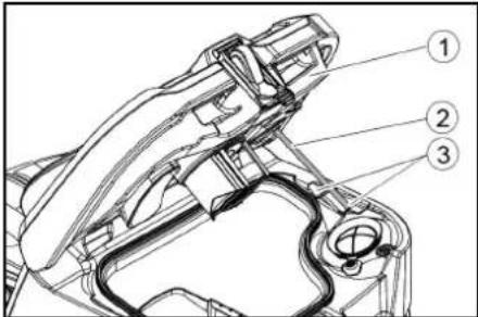
①Dirty water tank cover ②Attachments ③Step 5. If necessary, charge the battery.
Grey Intelligent Key
The grey Intelligent Key gives supervisory staff additional authorizations and setting options. 1. Insert the Intelligent Key. 2. Select the desired function by turning the information dial.
Transport mode
- Set the program selection switch to "TRANSPORT MODE".
- Press the information button. The following functions can be performed from the TRANSPORT MODE menu:
- Setting maximum speed • Display of operating hours counter • Resetting maintenance counter
- Display of software versions
- Setting R or D cleaning head
- Setting after-work time
- Setting language • Key management
- Activating factory settings
Maximum speed
In the "max speed" menu, the working speed can be limited.
- Turn the information button until "max speed" appears on the screen.
- Press the information button.
- Turn the information dial until the desired maximum speed is displayed.
- Press the information button. Note: The working speed cannot exceed the set maximum speed.
Storage
△CAUTION
1 Star knob
②Tension strap
③Inner part of the suction console
④ Tension lock
- Pull out the inner part of the suction console.
- Open the tension lock.
- Remove the tension strap.
- Release the suction rubbers from the inner part.
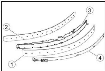
① Dirt collection wipers ② Additional wiper ③ Inner part of the suction console ④ Tension strap
- Push the used or new suction wipers onto the pins inside the suction console.
- Place the tension strap.
- Push the inner part of the suction console into the upper part.
- Screw and secure with the star handle screws.
Cleaning the coarse dirt filter
- Open the lid of the dirty water tank.
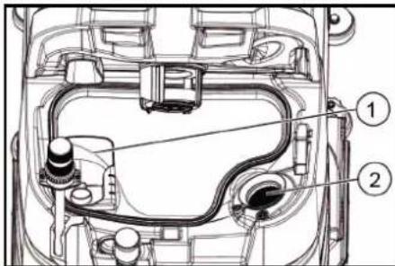
① Coarse dirt filter ② Lint filter 2. Remove the coarse dirt filter by pulling it upwards. 3. Rinse the coarse dirt filter under running water. 4. Insert the coarse dirt filter into the dirty water tank.
Cleaning the float and lint filter
- Open the lid of the waste water tank.
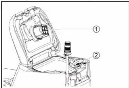
① Float ② Lint filter
- Rinse the float with clean water.
- Remove and clean the fiber filter.
① Brush replacement handle ② Storage cover with dirt collection rubber ③ Cylindrical brush
- Remove the storage cover with the dirt collection rubbers.
- Pull out the cylindrical brush.
- Insert a new cylindrical brush and center it on the rotating shaft.
① Holder
② Mounting mandrel
O
2006/42/EC (+2009/127/EC)
2014/30/EU
2014/53/EU (TCU)
Chairman of the Board of Management
S. Reiser
Director Regulatory Affairs & Certification
Person authorized to compile the documentation:
S. Reiser
Alfred Kärcher SE & Co. KG
Alfred-Kärcher-Str. 28 - 40
71364 Winnenden (Germany)
Tel.: +49 7195 14-0
① Handle
② Board
③ Bag
④ Frame
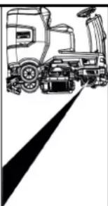
① Unlock lever
Storage
CAUTION
H. Jenner Chairman of the Board of Management
S. Reiser Director Regulatory Affairs & Certification
71364 Winnenden (Germany)
Tel.: +49 7195 14-0
Fax: +49 7195 14-2212
Winnenden, /09/01
Contents
General instructions 243
① Suction hose
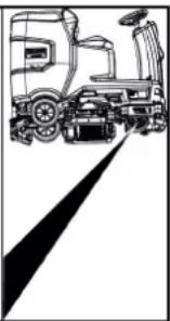
① Screw
② Nut
③ Level
① Nut
② Shim
Storage
△ CAUTION
Failure to comply with weight
① Sound signal
① Tension strap
② Board
③ Block
④ Wooden beam
① Screw
② Nut
③ Water level
① Nut
② Washer
Storage
△ CAUTION
Failure to comply with weight
S. Reiser Director Regulatory Affairs & Certification
71364 Winnenden (Germany)
Tel.: +49 7195 14-0
Fax: +49 7195 14-2212
①SCREW
②Nut
③Water level
①Nut
②Washer
Storage
⚠CAUTION
①Float
H. Jenner Chairman of the Board of Management
S. Reiser Director Regulatory Affairs & Certification
71364 Winnenden (Germany)
Tel.: +49 7195 14-0
Fax: +49 7195 14-2212
Winnenden, /09/01
Table of Contents
General notes.... 276
Function.... 276
Intended use 276
Environmental protection 276
Accessories and spare parts.... 276
Scope of delivery 276
Safety instructions…… 276
Device description.... 278
Installation 279
Commissioning.... 279
Operation 280
End of operation.... 281
Grey smart key 281
Transport.... 281
Storage.... 282
Maintenance and care 282
Troubleshooting.... 283
Quality assurance.... 284
Accessories 284
Technical data.... 284
EU Declaration of Conformity 285
General notes

www.kaercher.com/REACH
Accessories and spare parts
① Fresh water tank cap, tank with fresh water filter
② Coarse dirt filter
③ Waste water tank cover
④ Control panel
⑤ Squeegee adjustment wheel (only for D cleaning head)
⑥ Brush change pedal
⑦ Steering wheel
⑧ Squeegee blade
⑨ Battery
⑩ Nameplate
⑪ Seat adjustment lever
⑫ Storage area for cleaning kit "Homebase Box"
⑬* Warning light
⑭ Seat
⑮ Waste water tank unlocking device
⑯ Fresh water tank filling opening
⑰ Hose holder
18 Door switch, driving light
19 Accelerator pedal
20 Float
21 Fine filter screen
22 Wastewater drain hose
23 Wastewater tank
24* Mop holder
25 Suction hose
26 Squeegee clamping lever
27 Wastewater tank cover
28 Squeegee
29 Cleaning head
30 Fresh water level indicator
31 Fresh water tank
* Optional
Color marking
- Operating elements for cleaning processes are yellow
- Operating elements for maintenance and repair are light gray.
Control panel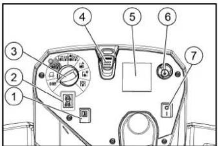
① Horn
② Travel direction switch
③ Program switch
④ Smart key
⑤ * Display
⑥ Information button
⑦ Safety switch
① Fastening strap
② Plate
③ Base
④ Square timber
① Battery plug, device side ② Battery plug, battery side
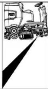
① Release lever
① Bolt ② Nut ③ Spirit level
① Nut ② Washer ③ Spacer roller and bracket
① Waste water tank cover
② Bracket
③ Level
- Charge the battery if necessary.
Grey smart key
Storage
△ Caution
Ignoring the weight
Risk of injury and damage
Note the weight of the device when storing.
Note
Frost
Frozen water causes damage to the equipment.
Completely drain the water from the equipment.
Store the equipment in a frost-free place.
- This equipment may only be stored indoors.
- Before prolonged storage, fully charge the battery.
① Star handle
② Fastening strap
③ Squeegee insert
④ Fastening cap
① Squeegee blade
② Support blade
③ Squeegee insert
④ Fastening strap
① Coarse debris filter
② Fine filter screen
① Float
② Fine filter screen
- Rinse the float with clean water.
- Remove the fine filter screen and clean it.
Replacing the brush disc
Note
① Brush handle
② Bearing cover with scraper blade
③ Brush roller
① Clean water filter
② Clean water tank sealing cap
① Siren
① Strap
② Board
③ Block
④ Beam
① Suction hose
② Suction bar suspension
③ Suction bar
④ Clamp lever
① Unlock lever
① Screw
② Nut
③ Level
① Nut
② Washer
③ Spacer roller with holder
① Water tank cap
② Support
③ Level
Storage
Caution
Ignore weight
Risk of injury and damage
① Star handle
② Strap
③ Inside of suction bar
④ Tension lock
① Wiper lip
② Support lip
③ Inside of suction bar
④ Strap
① Dirt filter
② Lint filter
① Float
② Lint filter
① Brush replacement handle
② Bearing cover with squeegee blade
③ Colora brush
2006/42/EG (-2009/127/EG)
2014/30/EU
2014/53/EU (TCU)
Application of harmonized standards
EN 60335-1
EN 60335-2-29
EN 60335-2-72
EN 62233: 2008
EN 55012: 2007 + A1: 2009
EN 61000-3-2: 2014
EN 61000-3-3: 2013
EN 61000-6-2: 2005
EN 61000-6-3:2007 + A1:2011
TCU (Telematic Control Unit)
EN 301 511 V12.5.1
EN 300 440 V2.1.1
EN 300 328 V2.2.2
EN 300 330 V2.1.1
Standards of the country of use
H. Jenner Chairman of the Board of Management
S. Reiser Director Regulatory Affairs & Certification
Authorized representative for this document:
S. Reiser
Alfred Kärcher SE & Co. KG
Alfred Kärcher Str. 28 40
71364 Winnenden (Germany)
Phone: +49 7195 14-0
2006/42/EG (-2009/127/EG)
2014/30/EU
2014/53/EU (TCU)
Applied harmonized standards
EN 60
EN 60335-2-29 EN 60335-2-72 EN 62233: 2008 EN 55012: 2007 + A1: 2009 EN 61000-3-2: 2014 EN 61000-3-3: 2013 EN 61000-6-2: 2005 EN 61000-6-3: 2007 + A1:2011 TCU (Telematics Control Unit) EN 301 511 V12.5.1 EN 300 440 V2.1.1 EN 300 328 V2.2.2 EN 300 330 V2.1.1
Standards of the country of use
H. Jenner Chairman of the Board of Management
S. Reiser Director Regulatory Affairs & Certification
Authorized representative for documentation:
S. Reiser
Alfred Kärcher SE & Co. KG
Alfred-Kärcher-Str. 28 - 40
71364 Winnenden (Germany)
Telephone: +49 7195 14-0
① Engine
② Direction switch
③ Program switch
④ Intelligent key
⑤ *Display
⑥ Warning button
⑦ Safety switch
① High-pressure hose
② Spray gun
③ Nozzle
④ Hose
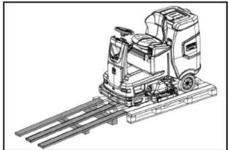
① Tunisia hose
② New air bar suspension
③ Vacuum bar
④ Joining lever
① Battery plug, device side
② Battery plug, battery side
① Release lever
① + screw
② Nut
③ Washer
① Needle
② Washer
③ Spacer roller with groove
① Desiccant cartridge
② Support
③ Step
5. If necessary, charge the battery.
Gray intelligent key
Storage
△ Caution
Non-compliance with weight
Risk of injury and damage
① Star figure
② Fixing weld
③ Inner part of vacuum bar
④ Clamp-type locking device
① Basing plan
② Support rim
③ Inner part of vacuum bar
Fixed mounting
1. Contaminated water outlet
2. Spare filter
1
2. Spare filter
- Rinse the float with clean water.
1. Water filter 2. Water tank locking device
H. Jenner Chairman of the Board of Management
S. Reiser Director Regulatory Affairs & Certification
Person responsible for document preparation:
S. Reiser
Alfred Kärcher SE & Co. KG
Alfred-Kärcher-Str. 28 - 40
71364 Winnenden (Germany)
Phone: +49 7195 14-0
Phone: +49 7195 14-2212
Winnenden, /09/01
EN 61000-3-2: 2014
EN 61000-3-3: 2013
EN 61000-6-2: 2005
EN 61000-6-3: 2007 + A1:2011
TCU
EN 301 511 V12.5.1
EN 300 440 V2.1.1
EN 300 328 V2.2.2
EN 300 330 V2.1.1
Chairman of the Board of Management
S. Reiser
Director Regulatory Affairs & Certification
اس رايزر
Alfred Kärcher SE & Co. KG
Alfred-Kärcher-Str. 28 - 40
71364 Winnende
∴ m = 3/11
ف
.
1
2
1
1
|
|
|
|
[Non-Text]
[Non-Text]
[Non-Text]
[Non-Text]
•
:
•
•
[Non-Text]
[Non-Text]
Item
•
[Unreadable]
ym
Item
Therefore m = 3/11
2.
2
1
1
|
|
|
|
|
□
5
©
4
3
5
□
1
1
1
1
1
)
-
1
②
⑤
(1)
9
1
②
⑤
(1)
Therefore m = 3/11
-
•
:
•
•
Project
•
Attachment
ym
Project
∴ m = 3/11
2.
2
:
•
•
Item
•
Attachment
2
a
1
|
|
1
-
5
2
4
.7
8
10
1
[Non-Text]
[Non-Text]
[Non-Text]
[Non-Text]
[Non-Text]
•
:
•
•
•
[Non-Text]
2017
Guangliyun Smart Retail Cashier System
∴ m = 3/11
and
1
-
41
|
|
|
|
|
|
1
②
①
1.2.3
4
6
1
1
1
21
1
1
|
2
©
3
4)
. f
。
10
1
©
3
4)
. f
-
广力云
Therefore, m = 3/11.
Therefore, m = 3/11.
q
1
.
1
-
41
|
|
|
|
©
3
4)
. f
∴ m = 3/11
•
:
•
Item
•
:
•
•
Item
•
- Information of delay times "I" (1)
① Screw
② Nut
③ Manifold gauge
5. Loosen the nut.
① Nut
② Washer
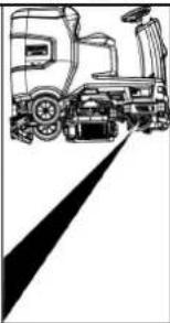
① Release lever
①. Connect the device
② Connect the battery
to the charger.
- Battery
on scale 4
① Suction hose
② Suction gauge marking
③ Suction gauge
④ Mounting arm
Belt ①
②
③ Grommet
④ Square wooden piece
① Fresh water inlet
② Coarse filter
③ Used water outlet
④ Control panel
⑤ Cleaning head
(only)
⑥ Brush start
⑦ Steering wheel
⑧ Side guards
⑨ Battery*
⑩ Type plate
⑪ Adjust the limit
① Tool holder
② Direction of travel switch
③ Program switch
④ Smart key
⑤ Display
⑥ Information button
⑦ Safety switch
THANK YOU!
Register your product and benefit from many advantages.
www.kaercher.com/welcome


Rate your product and tell us your opinion.
www.kaercher.com/dealersearch
Alfred Kärcher SE & Co. KG
Alfred-Kärcher-Str. 28-40
71364 Winnenden (Germany)
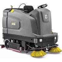
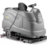
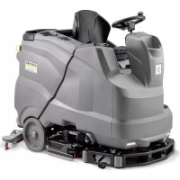
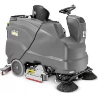
- CONTENTS
- STORAGE
- CAUTION
- GENERAL NOTES
- FUNCTION
- NOTE
- INTENDED USE
- ENVIRONMENTAL PROTECTION
- NOTES ON THE CONTENT MATERIALS (REACH)
- ACCESSORIES AND SPARE PARTS
- SCOPE OF DELIVERY
- SAFETY INSTRUCTIONS
- △WARNING
- THE DEVICE CAN TIP OVER
- RISK OF ACCIDENT DUE TO INCORRECT OPERATION
- SAFETY DEVICES
- MISSING OR MODIFIED SAFETY DEVICES
- SAFETY SWITCH
- SEAT SWITCH
- SYMBOLS ON THE DEVICE
- ATTENTION
- RISK OF DAMAGE
- DANGER OF BURNS
- DANGER
- DANGER OF ACCIDENT
- WARNING SYMBOLS
- DESCRIPTION OF THE UNIT
- OVERVIEW OF THE DEVICE
- COLOUR CODING
- CONTROL PANEL
- PROGRAM SWITCH
- INSTALLATION
- UNLOADING
- ④BEAM
- INSTALLING THE BRUSHES
- INSTALLING THE SUCTION BAR
- BATTERIES
- INSTALLING AND CONNECTING BATTERIES
- DEEP DISCHARGE
- REMOVING THE BATTERY
- △CAUTION
- INITIAL STARTUP
- CHARGING THE BATTERY
- INAPPROPRIATE USE OF THE CHARGER
- FLAMMABLE GASES ARE GENERATED WHEN THE BATTERY IS CHARGED
- ACCUMULATION OF DANGEROUS GASES UNDER THE TANK DURING THE CHARGING PROCESS
- EXTERNAL CHARGER
- RISK OF DAMAGE DUE TO UNSUITABLE CHARGER
- LOW-MAINTENANCE BATTERIES (WET BATTERIES)
- △DANGER
- REFILLING DISCHARGED BATTERIES WITH WATER
- USING WATER WITH ADDITIVES
- OPERATION
- FALLING OBJECTS
- RISKS DURING OPERATION
- PUSHING THE DEVICE
- ADJUSTING THE SEAT
- ADJUSTING THE POSITION
- SWITCHING THE DEVICE ON
- SWITCHING ON THE LIGHT
- DAYTIME RUNNING LIGHT
- CHECKING THE PARKING BRAKE
- DEFECTIVE PARKING BRAKE
- DRIVING
- LACK OF BRAKING
- CARELESS DRIVING
- FILLING WITH FRESH WATER
- FILLING WITH DETERGENT
- NOTES ON DETERGENTS
- ⚠ WARNING
- UNSUITABLE DETERGENTS
- FILLING THE DETERGENT INTO THE FRESH WATER TANK
- ADJUSTING PARAMETERS
- YELLOW INTELLIGENT KEY
- ADJUSTING THE SUCTION BAR
- ADJUSTING THE INCLINATION
- ADJUSTING THE HEIGHT
- ADJUSTING THE SQUEEGEE BLADES
- CLEANING
- FINISHING OPERATION
- FINISHING CLEANING
- DRAINING THE WASTE WATER
- IMPROPER DISPOSAL OF WASTE WATER ENVIRONMENTAL POLLUTION
- EMPTY THE COARSE DIRT CONTAINER
- DRAINING FRESH WATER
- SHUTTING DOWN THE UNIT
- GREY INTELLIGENT KEY
- TRANSPORT JOURNEY
- MAXIMUM SPEED
- RESETTING THE MAINTENANCE COUNTER
- ADJUSTING THE CLEANING HEAD
- AFTER-RUNNING TIME
- SETTING THE LANGUAGE
- KEY MANAGEMENT
- FACTORY SETTING
- ADJUSTING PARAMETERS FOR CLEANING PROGRAMS
- TRANSPORT
- DRIVING ON SLOPES
- FAILURE TO OBSERVE THE WEIGHT
- FROST
- CARE AND MAINTENANCE
- INADVERTENTLY STARTING UP DEVICE
- MAINTENANCE INTERVALS
- EACH TIME AFTER USE
- IMPROPER CLEANING
- WEEKLY
- MONTHLY
- ANNUALLY
- SAFETY INSPECTION/MAINTENANCE CONTRACT
- MAINTENANCE WORK
- TURN OVER OR REPLACE THE WORN SUCTION LIPS
- CLEANING THE COARSE DIRT FILTER
- CLEANING THE FLOAT AND FLUFF FILTER
- REPLACING THE DISC BRUSH
- REPLACING THE ROLLER BRUSHES
- CLEANING THE FRESH WATER FILTER
- CLEANING THE WATER DISTRIBUTION STRIP
- CLEANING BATTERIES
- TROUBLESHOOTING GUIDE
- MALFUNCTIONS WITH INFORMATION SHOWN ON THE DISPLAY
- WARRANTY
- ACCESSORIES
- DECLARATION OF CONFORMITY
- EU DECLARATION OF CONFORMITY
- NATIONAL STANDARDS USED
- DECLARATION OF CONFORMITY (UK)
- △ PRECAUTION
- ⚠CAUTION
- INDEX
- ① RELEASE HANDLE
- ③ SPIRIT LEVEL
- ① NUT
- ② WASHER
- ① DIRTY WATER TANK LID
- ② SUPPORT
- ③ LEVEL
- ⚠ CAUTION
- ①UNLOCKING LEVER
- DEPOLAMA
- TEDBIR
- ① SAFETY HANDLE
- △ CAUTION
- TABLE OF CONTENTS
- MOUNTING THE IMITATION BOARD
- ①RELEASE LEVER
- LADUSTAMINE
- △ETTEVAATUS
- KAALU EIRAMINE
- ⚠UZMANĪBU
- SVARA NEIEVĒROŠANA
- WHEEL REPLACEMENT
- INSTRUCTIONS
- ① UNLOCKING LEVER
- ①SCREW
- ②NUT
- ③WATER LEVEL
- ①NUT
- ②WASHER
- PART DESIGNATION
- MAINTENANCE-FREE BATTERIES (WET BATTERIES)
- SEAT ADJUSTMENT
- POSITION ADJUSTMENT
- TURNING ON THE DEVICE
- SETTING THE HEIGHT
- GRAY INTELLIGENT KEY
- ② FLAT WASHER
- RELEVANT EU DIRECTIVES
- MAINTENANCE-FREE BATTERIES (ELECTROLYTE BATTERIES)
- ① RELEASE LEVER
- ADJUST THE SEAT
- SET THE POSITION
- HEIGHT ADJUSTMENT
- TRANSPORT DRIVE
- LOW-MAINTENANCE BATTERIES
- (ELECTROLYTE BATTERIES)
- FILLING WATER WHEN THE BATTERY IS IN A DISCHARGED STATE
- DISPOSAL OF THE APPLIANCE
- TRANSPORT MODE
- CLEANING THE FLOAT AND LINT FILTER
- ① UNLOCK LEVER
- FAILURE TO COMPLY WITH WEIGHT
- COLOR MARKING
- GREY SMART KEY
- REPLACING THE BRUSH DISC
- ① SIREN
- IGNORE WEIGHT
- APPLICATION OF HARMONIZED STANDARDS
- STANDARDS OF THE COUNTRY OF USE
- AUTHORIZED REPRESENTATIVE FOR THIS DOCUMENT
- APPLIED HARMONIZED STANDARDS
- AUTHORIZED REPRESENTATIVE FOR DOCUMENTATION
- SPARE FILTER
- THANK YOU
Brand : Kärcher
Model : B 110 R Classic
Category : Industrial floor scrubber