
IS 3603 - Motion detector STEINEL - Free user manual and instructions
Find the device manual for free IS 3603 STEINEL in PDF.

| Product type | Passive infrared motion detector |
| Brand | Steinel |
| Model | IS 3603 |
| Dimensions | 121 mm diameter, 57 mm height |
| Weight | Approx. 200 g |
| Power supply | 220 – 240 V, 50/60 Hz |
| Detection technology | Passive infrared, 3 pyroelectric detectors |
| Detection angle | 360°, opening angle 90° |
| Range | Up to 12 m radius (installation height 2.50 – 2.80 m) |
| Trigger threshold (lux) | Adjustable from 2 lx (twilight) to 1000 lx (daylight mode) |
| Time delay | Adjustable from 5 seconds to 15 minutes |
| Max. incandescent/halogen lamp power | 2000 W |
| Max. LED power | Up to 600 W depending on type |
| Max. capacitive load | 176 μF |
| Protection rating | IP 54 |
| Operating temperature | -20 °C to +50 °C |
| Installation | On ceiling, recommended height 2.50 – 2.80 m |
| Connection | Terminals: N (neutral), L (phase), arrow (luminaire), PE (earth) |
| Forced lighting function | Yes (via two-way switch, 4 hours) |
| Warranty | 3 years (manufacturing defect) |
| Included accessories | Cover ring, shrouds, mounting accessories |
| Maintenance | Clean with a soft, dry cloth; do not use chemical products |
| Repairability | Repairs by Steinel after-sales service only |
Frequently Asked Questions - IS 3603 STEINEL
User questions about IS 3603 STEINEL
0 question about this device. Answer the ones you know or ask your own.
Ask a new question about this device
Download the instructions for your Motion detector in PDF format for free! Find your manual IS 3603 - STEINEL and take your electronic device back in hand. On this page are published all the documents necessary for the use of your device. IS 3603 by STEINEL.
USER MANUAL IS 3603 STEINEL
natural_image
World map silhouette in grayscale, showing continents and oceans without any text or labelsContact
www.steinel.de/contact

Intelligent technology
natural_image
Two identical white and black plastic kitchen utensils with textured surfaces, no visible text or symbols.Information
IS 360-3
A
natural_image
Simple circular diagram with concentric rings and a small label 'MILK' at the top (no text or symbols within the rings)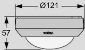
B
C
natural_image
Technical line drawing of a mechanical component with internal structure and directional arrow (no text or symbols)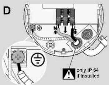
natural_image
Technical illustration of a mechanical component with a magnified inset showing a tool interacting with it (no text or symbols present)E
1
2
3

4
F
natural_image
Technical illustration of a mechanical component with a downward arrow indicating rotation (no text or symbols present)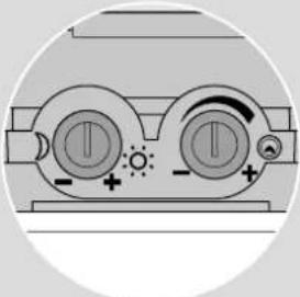
natural_image
Diagram of a mechanical device with circular ports and directional indicators, no text or symbols present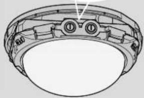
natural_image
Technical line drawing of a mechanical bearing assembly (no text or symbols)
5 sec – 15 min

2 - 1000 Lux
Montageanleitung
Zu dieser Anleitung
Installation instructions
About these instructions
Instructions to take action are shown as follows:
▶ Instruction to take action
In the safety advice, the warning symbol and signal word indicate the severity of danger:

Signal word
Type and source of danger
Measures to avoid dangers
▶ Read these installation instructions before installing the product.
Further information
You will find further information at: www.steinel.de
Proper use
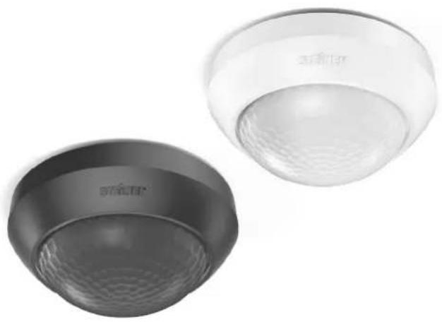
The IS 360-3 outdoor sensor can be used as an indoor and outdoor motion detector. Working with three pyro sensors, it detects heat radiated from moving objects and switches ON lights that are connected to it. The product is only suitable for installing on ceilings and may only be operated in line with the technical specifications.
All connecting work at the electrical connections may only be carried out by a qualified electrician and in compliance with national regulations.
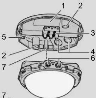
Product parts (Fig. A)
Holder for ceiling mounting
1 Rating plate
2 Mounting holes
3 Connections
N neutral conductor
ArrowPower supply lead for light
L Mains power supply
4 Cable entries
5 Contact point for protective-earth conductor
Sensor housing
6 two control dials:
Response threshold and stay-ON time
7 Housing attachment with screw
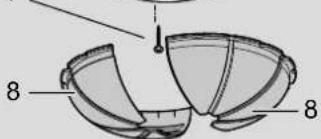
8 Shrouds
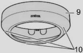
9 Cover ring
10 Pilot holes for drainage
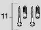
11 Fixing material
Checking package contents and product
▶ Check to make sure that the product is complete and undamaged.
▶ Do not open the housing if it is damaged, and do not repair the product yourself.
▶ Carefully pack the damaged product and send it with a brief description of the fault and proof of purchase (in-voice) to a Steinel service station.
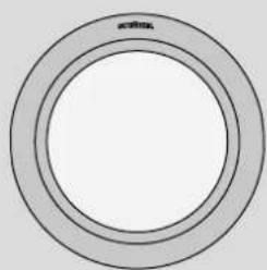
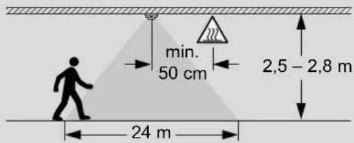
Preparing to install (Fig. B)
Defining point of installation
▶ Define the mounting position as follows:
• Minimum distance of 50 cm from lights and other sources of heat
- Unobstructed line of vision between the sensor and detection zone (obstacles include walls, glass panels, trees)
- Mounting height of 2.50 m to 2.80 m for optimum reach
Planning usage

Caution
Risk of short-circuiting from overloading
When planning the number of lights to connect, always be sure not to exceed the maximum switching capacity, e.g. 2000 watts for light bulbs, see section "Technical specifications".
Checking ambient conditions
If you are using the product in a very damp or humid environment:
▶ Drill drainage holes in the pilot holes (10) using a 5 mm drill bit
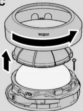
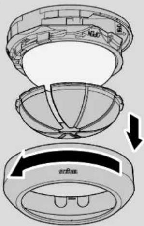
Installing (Fig. C)

Danger
Danger to life from touching live cables!
Disconnect cables from the power supply!
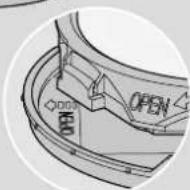
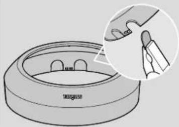
▶ Detach the cover ring (9) and the shrouds (8).
▶ Undo the housing attachment screw (7) and push it out of the holder.
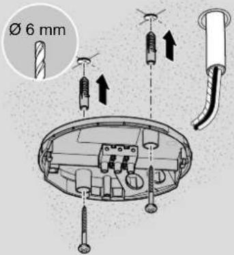
▶ Drill holes at the intended mounting position.
▶ Attach the holder with the fixing material (11).
Connecting IS 360-3 (Fig. D)

Danger
Danger to life from electric shock!
All work at the connections may only be performed by a qualified electrician.
▶ Using a voltage tester, check to make sure that all cables are disconnected from the power supply.
▶ Thread the cables through the cable entries (4).
▶ Attach the PE conductor (yellow and green conductor) at the contact point (5).
▶ Connect the neutral conductor (blue or grey conductor) to the neutral conductor terminal N.
▶ Connect the live (black) conductor to the mains power supply terminal L.
Connecting power supply lead for lights
▶ Connect the power supply lead for light (brown) to the arrow terminal.
Note
Protection class IP54 is only ensured if the sealing plugs are fitted.
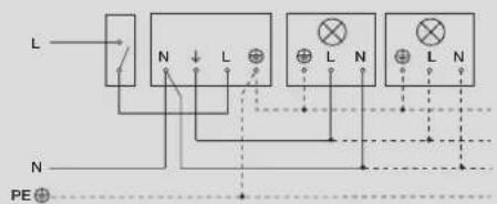
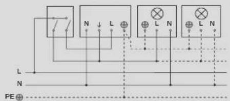
Connection examples (Fig. E)

Danger
Danger to life from electric shock!
All work at the connections may only be performed by a qualified electrician.
Connecting lights
▶ Connect lights that do not have a neutral conductor as shown in connection example 1.
▶ Connect lights that do have a neutral conductor as shown in connection example 2.
Installing two-circuit switch
If you want to switch OFF all connected lights via switch:
▶ install a two-circuit switch for manual and automatic operation (connection example 3).
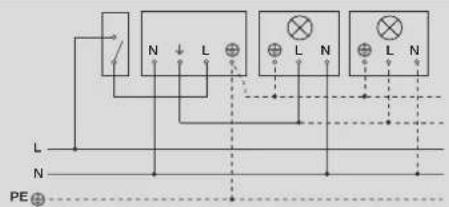
Installing two-way switch
If you want to switch ON and OFF manually and also use sensor mode (automatic):
▶ Install a two-way switch (connection example 4).
Two-way switch options:
- Position I Sensor mode (switching ON and OFF automatically)
- Position II manual operating mode: switching ON and OFF via switch; after switching OFF, sensor mode is reactivated
Activating and deactivating manual override
A two-way switch provides a manual override function for lights connected.
To activate manual override:
▶ Turn the light switch to the OFF and ON positions twice in rapid succession (within less than half a second). Manual override keeps light ON permanently for four hours and then returns to sensor mode.
To deactivate manual override:
▶ Turn the light switch to the OFF and ON position once in rapid succession (within less than half a second). The light immediately switches to sensor mode.
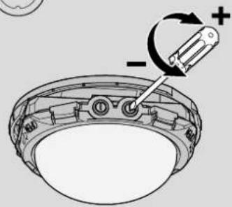
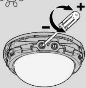
Settings (Fig. F)
During installation or at a later time, you can infinitely adjust the stay-ON time and the response threshold via the control dials.
▶ Using a screwdriver, turn the control dials to the chosen positions:

Stay-ON time
+ maximum: 15 minutes - minimum: 5 seconds
If you have set a stay-ON time of 15 minutes, the sensor will switch OFF the connected lights after 15 minutes.
If the sensor detects further movement, the stay-ON time will start from the beginning again.
Using the response threshold, you can infinitely adjust the level of ambient light at which the sensor switches on the lights connected.

Response threshold
+ maximum: 1000 lux
Daylight mode: the sensor switches light ON in day-light when it identifies a movement.

- minimum: 2 lux
Twilight setting: the sensor switches light ON at twilight. If the ambient brightness is brighter than 2 lux, the sensor does not switch light ON.
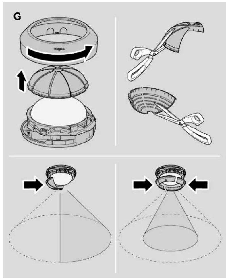
Detection zone (Fig. G)
Is the sensor switching light ON too often because it is being triggered by objects in the detection zone (e.g. in response to passing vehicles)?
You can mask the sensor with shrouds (8) to restrict the detection zone.
▶ Detach the cover ring and the shrouds.
▶ Using a pair of scissors, cut the shrouds to size horizontally and/or vertically.
▶ Fit the shrouds to the sensor and, if necessary, adjust them to the appropriate position.
▶ Re-fit the cover ring.
Operation
Perform function test
▶ Set the response threshold to the current ambient brightness. The factory setting is daylight operation.
▶ Set the stay-ON time to a very short period. The factory setting is 5 seconds.
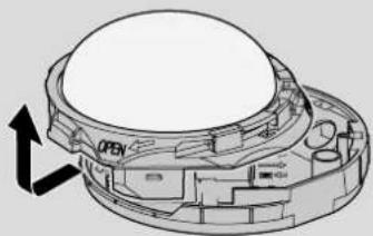
▶ Fit the sensor housing onto the holder and push it home until it clips into place.
▶ Tighten the housing attachment screw (7).
▶ Switch the power ON.
▶ Check whether the sensor responds to a movement and switches the light ON.
If it does, the sensor is ready for operation:
▶ Select your chosen settings and refit the cover ring (9).
If it does not:
▶ Check the connections and the voltage supply.
Troubleshooting

Danger
Danger to life from touching live components!
All work at the connections may only be performed by a qualified electrician. Disconnect cables from the power supply!

Attention
Product damage from improper servicing
Servicing or repair work may only be performed by Steinel service stations.
Sensor will not switch ON
Either incorrect settings have been made, there is a power-related fault or the sensor is faulty:
▶ Check the setting for the response threshold and, if necessary, set a higher lux level.
▶ Check the cables, connections and the voltage supply, change a fuse if necessary.
▶ Carry out a function test on the sensor and on the lights connected, replacing any faulty items.
Sensor will not switch OFF
Either incorrect settings have been made, manual override is activated or there is permanent movement or a source of heat in the detection zone.
▶ Check whether the response threshold setting is too low, correcting the setting if necessary.
▶ Check whether the light has been switched ON manually via a switch.
▶ Check whether there are any sort of heat or anything else inadvertently triggering the sensor in the detection zone and remove them.
▶ If necessary, limit the detection zone with the shrouds.
Sensor switching ON when it should not
The sensor is detecting constant movement or a source of heat in the detection zone, causing it to switch ON too often or when it should not.
▶ Check the detection zone for sources of heat or movement.
▶ Eliminate permanent sources of heat from the detection zone.
▶ If necessary, limit the detection zone with the shrouds.
Disposal
Electrical and electronic equipment, accessories and packaging must be recycled in an environmentally compatible manner.

Do not dispose of electrical and electronic equipment as domestic waste.
EU countries only: Under the current European Directive on Waste Electrical and Electronic Equipment and its implementation in national law, electrical and electronic equipment no longer suitable for use must be collected separately and recycled in an environmentally compatible
Warranty

Steinel provides a 3-year warranty from the date of purchase for defects caused by material flaws or manufacturing faults.
Once the warranty expires, Steinel provides a repair service at its service stations via the factory service.
Service
▶ Contact the service stations through your country's branch of Steinel Vertrieb GmbH. You will find contact details on the back of these instructions.
Technical specifications
Dimensions and versions
| ∅ × height 121 m | m × 57 mm |
| Colours white, black | |
Specifications
| Supply voltage 220 – 240 V | |
| Mains frequency 50/60 Hz | |
| Additional switching capacities | |
| Incandescent / halogen lamp load | 2000 W |
| Fluorescent lamps, electronic ballast | 1500 W |
| Fluorescent lamps, uncorrected | 500 VA |
| Fluorescent lamps, series-corrected | 900 VA |
| Fluorescent lamps, parallel-corrected | 400 VA |
| Low-voltage halogen lamps | 2000 VA |
| LED < 2 W | 100 W |
| 2 W < LED < 8 W | 300 W |
| LED > 8 W | 600 W |
| Capacitive load | 176 μF |
Sensor
| Sensor technology | Passive infrared, 3 pyro sensors |
| Angle of coverage | 360° |
| Angle of aperture | 90° |
| Sneak-by guard provided | |
Reach and settings
| Detection zone and reach | 12 m, at a mounting height of 2.50 m to 2.80 m |
| Switching ON at threshold levels | 2 lux to 1000 lux, (daylight operation) |
| Stay-ON time, continuously variable | 5 seconds to 15 minutes |
Environment
| IP rating IP54 | |
| Temperature range | -20°C to +50°C |
Date privind puterea