
PAN 186 - Multimeter Pancontrol - Free user manual and instructions
Find the device manual for free PAN 186 Pancontrol in PDF.
| Brand | Pancontrol |
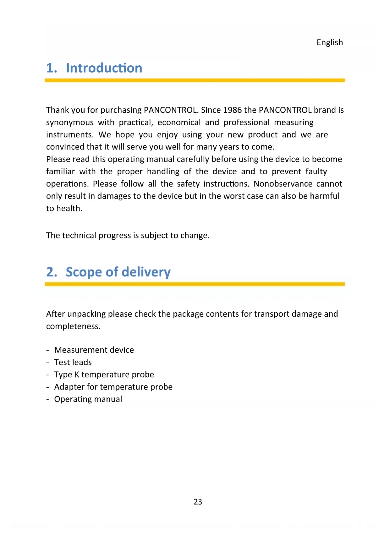
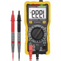
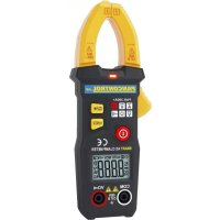
| Model | PAN 186 |
| Product type | Digital multimeter |
| Display | 3 3/4 digits (5999 counts), backlight |
| Main functions | DC/AC voltage (V DC/AC), DC/AC current (A DC/AC), resistance (Ω), capacitance (F), frequency (Hz), temperature (°C/°F), diode test, continuity test, non-contact voltage tester (NCV) |
| Maximum voltage | 1000 V DC / 750 V AC |
| Maximum current | 10 A AC/DC (up to 30 seconds) |
| Input impedance | 10 MΩ |
| Power supply | 4 AA 1.5 V batteries |
| Dimensions (L x W x H) | 190 x 89 x 50 mm |
| Weight | Approximately 380 g (with batteries) |
| Overvoltage category | CAT III 1000 V / CAT IV 600 V |
| Safety | Double insulation, protection fuses (FF 600 mA H 1000 V and FF 10 A H 1000 V) |
| Standards | CE (EN-61010) |
| Provided accessories | Test leads, type K temperature probe, probe adapter, instruction manual |
| Warranty | 2 years legal warranty |
| Maintenance | Clean with a damp cloth and mild detergent; replace batteries if low battery symbol appears |
Frequently Asked Questions - PAN 186 Pancontrol
User questions about PAN 186 Pancontrol
0 question about this device. Answer the ones you know or ask your own.
Ask a new question about this device
Download the instructions for your Multimeter in PDF format for free! Find your manual PAN 186 - Pancontrol and take your electronic device back in hand. On this page are published all the documents necessary for the use of your device. PAN 186 by Pancontrol.
USER MANUAL PAN 186 Pancontrol
- Introduction ...... 23
- Scope of delivery 23
- Safety Instructions.... 24
- Symbols Description.... 26
- Panel Description 27
- Symbols of the Display 29
- General Specifications.... 30
- Operating Instructions 32
- Maintenance 37
- Guarantee and Spare Parts 39
1. Introduction
Thank you for purchasing PANCONTROL. Since 1986 the PANCONTROL brand is synonymous with practical, economical and professional measuring instruments. We hope you enjoy using your new product and we are convinced that it will serve you well for many years to come.
Please read this operating manual carefully before using the device to become familiar with the proper handling of the device and to prevent faulty operations. Please follow all the safety instructions. Nonobservance cannot only result in damages to the device but in the worst case can also be harmful to health.
The technical progress is subject to change.
2. Scope of delivery
After unpacking please check the package contents for transport damage and completeness.
- Measurement device
- Test leads
- Type K temperature probe
- Adapter for temperature probe
- Operating manual
3. Safety Instructions
- To ensure the safe use of the device, please follow all the safety and operating instructions given in this manual.
- Before using the device, make sure that test leads and the device are in good condition and the device is working properly (e.g. by connecting to known voltage sources).
- The device may not be used if the housing or the test leads are damaged, if one or more functions are not working, if functions are not displayed, or if you suspect that something is wrong.
- If the safety of the user cannot be guaranteed, the device may not be operated and secured against use.
- While using this device, hold the test leads only behind the finger guards - do not touch the probes.
- Never ground yourself while making electrical measurements. Do not touch any exposed metal pipes, fittings etc., which could have a ground potential. Ensure that your body is isolated by using dry clothes, rubber shoes, rubber mats or other approved insulation materials.
- Operate the device in a way that it is not difficult to operate the network separators.
- Always adjust the rotary switch to the desired measuring range before starting the measurement and engage the switch in the proper measuring range.
- If the magnitude of the signal to be measured is not known, always start with the highest measuring range on the rotary switch and then reduce step-by-step.
- If the measuring range needs to be changed during the measurement, remove the probes from the circuit first.
- Never connect the device to voltage or current sources that exceed the specified maximum values.
-
Disconnect the power supply and discharge the filter capacitors in the power supply before measuring resistance or testing diodes.
-
Never connect the test leads of the device to a voltage source, if the rotary switch is set to measure current, resistance or test diodes. This can damage the device.
- If the battery symbol appears in the display, replace the battery immediately.
- Always switch off the appliance and remove the test leads from all voltage sources before opening the device to exchange the battery or the fuse.
- Never use the device with the rear cover removed or with the battery and fuse compartment open!
- Do not use the device near strong magnetic fields (for e.g. welding transformer), as this can distort the display.
- Do not use the device outdoors, in humid surroundings or in environments that are subjected to extreme temperature fluctuations.
- Never use the device in an explosionprone environment.
- Do not store the device in places which are exposed to direct sunlight.
- Remove the battery if the device is not used for a long time.
- If changes or modifications are made to the device, the operational safety is no longer guaranteed and the warranty becomes void.
4. Symbols Description
| CE | Conforms to the relevant European Union directive (EN-61010) |
 | Product is protected by double insulation |
 | Risk of Danger. Important information See instruction manual |
 | Attention! Hazardous voltage. Risk of electric shock. |
 | This product should not be disposed along with normal domestic waste at the end of its service life but should be handed over at a collection point for recycling electrical and electronic devices. |
| CAT III(1000 V) | The device is designed for making measurements in building installations. Examples are measurements on junction boards, circuit breakers, wiring, switches, permanently installed sockets, devices for industrial use as well as permanently installed motors. |
| CAT IV(600 V) | The device is designed for making measurements at sources of low voltage installations. Examples are meters and measurements on primary overload protection devices and ripple control devices. |
| FUSED | Fused current measuring range |
| ~ | AC voltage / current (AC) |
| --- | DC voltage / current (DC) |
| ≈ | AC / DC |
| Battery compartment | |
| ⊥ | Ground / Earth (max. voltage to earth) |
5. Panel Description
Note Fig.. 1
- Display
- Function keys
- Rotary switch
- Input terminal
- Non Contact Voltage tester Display
- Non Contact Voltage tester Sensor
Function keys
| SEL(2.1) | Function selector switch |
  | Point Illumination (Flashlight) |
  | Data Hold (keep displayed value) /Backlight |
Input terminal
| V Ω Hz%°C / °F ... | Multi-function jack |
| 10 A | 10 A-jack (AC and DC) |
| μA, mA | μA/mA-jack (max. 600 mA - only DC) |
| COM | Joint connector (black) |
Symbols of the rotary switch
| OFF | Device switched OFF |
| NCV | Non Contact Voltage tester |
| V ≈ | DC Voltage measurement / AC Voltage measurement |
| →←→→ | Diode testing / Continuity test |
| Ω | Resistance measurement |
| ←← | Capacity measurement |
| TEMP | Temperature measurement |
| Hz % | Frequency measurement and Duty cycle |
| μA | DC current measurement μA |
| mA | DC current measurement mA |
| A ≈ | DC current measurement / AC Current measurement to 10A |
6. Symbols of the Display
Note Fig. 2
 | AC voltage / current | |
| DC== | DC voltage / current | |
 | Battery low | |
| Standby-operation | ||
 | Automatic range selection active | |
 | Diode test active | |
| Audible continuity test active | ||
 | Data hold (keep displayed value) | |
 | Non Contact Voltage tester | |
 | Temperature measurement | |
 | Resistance measurement | |
 | DC current measurement / AC Current measurement | |
 | DC Voltage measurement / AC Voltage measurement | |
 | Overload indicator | |
This device does not use all the symbols shown in the image.
7. General Specifications
| Display | 3 3/4 Digits (to 5999) |
| Overload indicator | OL |
| Polarity | automatically (minus sign for negative polarity) |
| Measuring rate | 3 / s |
| Overload protection | 1000 V |
| Internal impedance | 10 MΩ |
| Continuity test | Beeping sound in less than 40 Ω |
| Diode testing | Open circuit voltage: 3,2 VTest current: < 1 mA |
| Power supply | 4 x 1,5 V (AA) Battery(s) |
| Auto power off | 15 s (Standby-operation) |
| Operating temperature | 0°C to 40°C / < 80% Humidity |
| Storage temperature | -10°C to 60°C(Remove the battery if Humidity >70%) |
| Fuse(s) | mA, μA -Range:FF 600 mA H 1000 V - 6 x 32 mmA-Range: FF 10 A H 1000 V - 6 x 32 mm |
| Weight | ca. 380 g (with Battery(s)) |
| Dimensions | 190 x 89 x 50 mm |
| Function | Range | Resolution | Accuracy of the value displayed in % |
| DC voltage (V=) | 600 mV | 0,1 mV | ±(0,5% + 3 digits) |
| 6 V | 1 mV | ||
| 60 V | 10 mV | ||
| 600 V | 100 mV | ||
| 1000 V | 1 V | ||
| AC voltage (V~) true RMS | 6 V | 1 mV | ±(0,8% + 3 digits) |
| 60 V | 10 mV | ||
| 600 V | 100 mV | ±(1,0% + 10 digits) | |
| 750 V | 1 V | ||
| DC current (A=) | 60 μA | 0,01 μA | ±(0,8% + 3 digits) |
| 600 μA | 0,1 μA | ||
| 6 mA | 0,001 mA | ||
| 60 mA | 0,01 mA | ||
| 600 mA | 0,1 mA | ||
| 10 A | 10 mA | ±(1,2% + 3 digits) | |
| AC current (A~) | 60 μA | 0,01 μA | ±(1,0% + 3 digits) |
| 600 μA | 0,1 μA | ||
| 6 mA | 0,001 mA | ||
| 60 mA | 0,01 mA | ||
| 600 mA | 0,1 mA | ||
| 10 A | 10 mA | ±(1,5% + 3 digits) | |
| Resistance (Ω) | 600 Ω | 0,1 Ω | ±(0,8% + 3 digits) |
| 6 kΩ | 1 Ω | ||
| 60 kΩ | 10 Ω | ||
| 600 kΩ | 100 Ω | ||
| 6 MΩ | 1 kΩ | ||
| 60 MΩ | 10 kΩ | ±(1,2% + 30 digits) | |
| Frequency (Hz) | 9,999 Hz | 0,001 Hz | ±(1,0% + 3 digits) |
| 99,99 Hz | 0,01 Hz | ||
| 999,9 Hz | 0,1 Hz | ||
| 9,999 kHz | 0,001 kHz | ||
| 99,99 kHz | 0,01 kHz | ||
| 999,9 kHz | 0,1 kHz | ||
| 9,999 MHz | 1 kHz | ||
| Capacitance (F) | 6 nF | 0,001 nF | ±(4,0% + 30 digits) |
| 60 nF | 0,01 nF | ±(4,0% + 3 digits) | |
| 600 nF | 0,1 nF | ||
| 6 μF | 1 nF | ||
| 60 μF | 10 nF | ||
| 600 μF | 100 nF | ||
| 6 mF | 1 μF | ||
| 100 mF | 0,01 mF | ±(5,0% + 3 digits) | |
| Temperature °C | -20 ... 1000 °C | 1 °C | ±(1,0% + 3 digits) |
| Temperature °F | -4 ... 1832 °F | 1 °F | ±(1,0% + 3 digits) |
8. Operating Instructions
- Always switch OFF the device when it is not in use.
- Be aware of the Safety Instructions (Chapter 3)
- Please refer to the sketches on the first pages of this manual.
- If "OL" is displayed while measuring the value exceeds the used range. Switch to a higher range if available..
Attention!
Due to the high sensitivity the reading sometimes shows random values if the test leads are not connected to any signal. The reading stabilizes when the test leads are connected to the circuit to be tested.
Avoid voltage measuring in electrical circuits while motors are switched on or off. The stress-spikes can damage the instrument.
Hazardous voltage! The probes may not be long enough to touch the hot parts in some 230V wall sockets as they are deep inside. As a result, the reading can show 0 volts. Make sure that the probes touch the metallic contacts in the socket before assuming that voltage has not been applied.
Devices like welding transformer, car ignition system, etc. could produce stray electromagnetic fields which could adulterate the result of a measurement.
Data Hold (keep displayed value)
If the reading could not be read during measurement due to difficult operation the „HOLD“-button (2.3) could be pressed to freeze the display reading.
Press the „HOLD“-button to freeze the display reading.
The display shows the „HOLD“-symbol to indicate the activated HOLD function.
Press the „HOLD“-button again to return to standard operation.
Backlight
To turn the backlight on or off, press for two seconds the button 2.3
Point Illumination (Flashlight)
In low light conditions, you can illuminate the point. To do this, press the button (2.2).
DC Voltage measurement / AC Voltage measurement
Attention!
DC voltage max. 1.000 V
AC voltage max. 750 V
- Set the rotary switch to the position V
- Attach the pin-plug of the black test lead to the COM-jack and the pin-plug of the red test lead to the multi-function jack.
- Touch the measuring points with the probe tips.
- Once the reading stabilizes, read the value.
DC: If the polarity is reversed a "Minus sign" is displayed.
DC current / AC Current measurement
Note:
AC current measurements can be carried out only in the 10 A range.
Avoid current measurements with the 10A setting for more than 30 seconds.
This can damage the device and / or the test leads.
- For measurements up to 6000 A (mA) set the rotary switch to the A (mA)-Position and attach the pin-plug of the red test lead to the A (mA)-jack. For measurements up to 10 A set the rotary switch to the A-Position and attach the pin-plug of the red test lead to the 10 A-jack.
- Touch the measuring points with the probe tips.
- Once the reading stabilizes, read the value.
DC: If the polarity is reversed a "Minus sign" is displayed.
Non Contact Voltage tester
- Set the rotary switch to the position NCV
- Hold the tip of the measuring instrument to an electrical outlet or to a cable. When the voltage is applied, a beep sounds and the LED indicator (5) lights up. - Depending on the height of the voltage, first the green and then the red LEDs light up.
Attention!
Even without an alarm, dangerous voltage can be concerned! This depends on various factors. Therefore, if necessary, check the zero voltage with the voltmeter.
Frequency measurement and Duty cycle
Attention!
Frequency and duty cycle measurement can only be performed at a voltage between 0.2 V\~ and max. 10 V\~!
- Set the rotary switch to the position Hz %
- Select with the "SEL" button Hz or %
- Attach the pin-plug of the black test lead to the COM-jack and the pin-plug of the red test lead to the multi-function jack.
- Once the reading stabilizes, read the value.
Attention!
Disconnect the power supply and discharge all capacitors before performing the following measurements.
Resistance measurement
- Set the rotary switch to the position
- Attach the pin-plug of the black test lead to the COM-jack and the pin-plug of the red test lead to the multi-function jack.
- Touch the measuring points with the probe tips.
- Once the reading stabilizes, read the value.
Continuity test / Diode testing

- Set the rotary switch to the position
- Attach the pin-plug of the black test lead to the COM-jack and the pin-plug of the red test lead to the multi-function jack.
- Touch the measuring points with the probe tips.
Continuity test:
If the resistor is less than 40 , you will hear a beep and the green LEDs will light up. With a resistance between 40 and 60 , the red LEDs light up.
When the circuit is open, the display shows "OL".
Diode testing:
Touch the diode to be tested with the probes. The forward voltage shows 400 to 700mV. The counter voltage shows „OL”. Defective devices show a value about 0 mV or „OL” in both polarities.
Capacity measurement

- Set the rotary switch to the position
- Attach the pin-plug of the black test lead to the COM-jack and the pin-plug of the red test lead to the multi-function jack.
- For capacitors with known polarity connect the red test lead with the anode and the black test lead with the cathode. Once the reading stabilizes, read the value. Use the HOLD function if the reading is difficult to read.
Temperature measurement
- Set the rotary switch to the position TEMP
- Select with the "SEL" button °C or °F
-
Attach the adaptor of the temperature probe to the instrument. ( - Symbol to the COM jack and - Symbol to the multi-function jack.) Press SEL to select ^ F or ^ C.
-
Connect the device to the K-probe. Observe the correct polarity! (Red: °C/°F, Black: COM)
- Connect the temperature probe to the device to be tested wait a few moments and read the value displayed. If necessary, use heat conducting paste.
9. Maintenance
Only authorized service technicians may repair the instrument.
If the instrument is malfunctioning, please test:
- Battery condition and polarity
- Condition of the fuse(s) if available.
- Condition of the test leads.
Attention!
Always switch off the appliance and remove the test leads from all voltage sources before opening the device to exchange the battery or the fuse.
Changing the battery(s)
Replace the battery(s) when the battery symbol or BATT is displayed on the LCD.
- Open the battery compartment.
- Replace the spent battery with a new one - note the correct polarity
- Replace the battery compartment lid and secure the screw.
- Disposal of the flat battery should meet environmental standards.
Changing the fuse(s)
- Open the device.
- Remove the broken fuse carefully from ist holder.
- Reinset the new fuse and ensure proper fitting. Use equivalent fuses only.
- Replace the cover and secure the screw.
Cleaning
If the instrument is dirty after daily usage, it is advised to clean it by using a humid cloth and a mild household detergent. Prior to cleaning, ensure that instrument is switched off and disconnected from external voltage supply and any other instruments connected. Never use acid detergents or dissolvent for cleaning.
10. Guarantee and Spare Parts
PANCONTROL instruments are subject to strict quality control. However, should the instrument function improperly during daily use, your are protected by a 24 months warranty from the date of purchase (valid only with invoice).
Only trained technicians may carry out repairs to this device.
Further information on complaint handling can be found at:
In case of spare part requirement or in case of queries or problems, please get in touch with your vendor or:

Dipl.Ing. Ernst KRYSTUFEK GmbH & Co KG
Error and misprints reserved. Vienna, September 2020

Non-contact spanning tester
Wenen, September 2020

Bruksanvisning
PAN 186
Digital multimeter true RMS
Innehåll
Mjerenje temperature
- Podesite okretnu sklopku u položaj TEMP
-
Odaberite gumb "SEL" °C ili °F
-
Utaknite međuutikač temperaturnog senzora sa simbolom ⊖ - u COM utičnicu, a onaj sa simbolom ⊕ u multi-function utičnica. Stisnite tipku SEL sve dok se na zaslonu ne pojavi jedinica °F ili °C.
- Priključite napravo na K-sonde. Opazovati na pravilno polarnost! (Crveno: °C/°F, Crna: COM)
- Dodirnite predmet mjerenja senzorom temperature i pričekajte dok se vrijednost na zaslonu stabilizira, te pročitajte izmjerenu vrijednost. Ako je potrebno, koristite topline provođenje tijesto.
9. Popravci
Non-contact tensiune tester
- Introduction
- Scope of delivery
- Safety Instructions
- Symbols Description
- Panel Description
- Note Fig.. 1
- Function keys
- Input terminal
- Symbols of the rotary switch
- Symbols of the Display
- General Specifications
- Operating Instructions
- Attention!
- Data Hold (keep displayed value)
- Backlight
- Point Illumination (Flashlight)
- DC Voltage measurement / AC Voltage measurement
- DC current / AC Current measurement
- Note:
- Non Contact Voltage tester
- Frequency measurement and Duty cycle
- Resistance measurement
- Continuity test / Diode testing
- Continuity test:
- Diode testing:
- Capacity measurement
- Temperature measurement
- Maintenance
- Changing the battery(s)
- Changing the fuse(s)
- Cleaning
- Guarantee and Spare Parts
- Non-contact spanning tester
- Bruksanvisning
- PAN 186
- Digital multimeter true RMS
- Innehåll
- Mjerenje temperature
- Popravci
- Non-contact tensiune tester
Brand : Pancontrol
Model : PAN 186
Category : Multimeter