
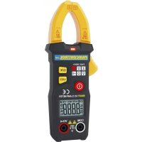
PAN 3000A+ True RMS - Measuring equipment Pancontrol - Free user manual and instructions
Find the device manual for free PAN 3000A+ True RMS Pancontrol in PDF.

| Product type | Flexible True RMS digital clamp meter |
| Brand | Pancontrol |
| Model | PAN 3000A+ True RMS |
| Category | Measurement equipment |
| Main functions | Alternating current (AC), alternating voltage (AC), direct voltage (DC), frequency, resistance, continuity check |
| Display | LCD with backlight, 3 3/4 digits (5999 counts) |
| AC current measuring range | 60 A / 600 A / 3000 A (depending on frequency) |
| AC/DC voltage measuring range | 6 V / 60 V / 600 V |
| Resistance measuring range | 6 kΩ / 60 kΩ / 600 kΩ / 6 MΩ |
| Measurable frequency | 40 Hz - 10 kHz (voltage) / 40 Hz - 1 kHz (current) |
| Overvoltage category | CAT IV 600 V |
| Max. voltage to ground | 600 V |
| Input impedance | 2 MΩ |
| Range selection | Automatic (no manual selection) |
| HOLD function | Yes (freeze measured value) |
| Backlight / Spotlight | Yes |
| Auto-off | After approx. 5 minutes of inactivity |
| Dimensions (L x W x H) | 178 x 324 x 30 mm |
| Weight | 220 g (with batteries) |
| Power supply | 3 AAA 1.5 V batteries |
| Operating conditions | 0 °C to 40 °C, humidity < 80 % |
| Maintenance and cleaning | Clean with a damp cloth and mild detergent; do not use solvents |
| Safety | Double insulation, follow the instructions in the manual, do not use if damaged |
| Warranty | 2 years legal warranty |
| Spare parts and reparability | Repairs by qualified personnel; contact the dealer or KRYSTUFEK.at |
Frequently Asked Questions - PAN 3000A+ True RMS Pancontrol
User questions about PAN 3000A+ True RMS Pancontrol
0 question about this device. Answer the ones you know or ask your own.
Ask a new question about this device
Download the instructions for your Measuring equipment in PDF format for free! Find your manual PAN 3000A+ True RMS - Pancontrol and take your electronic device back in hand. On this page are published all the documents necessary for the use of your device. PAN 3000A+ True RMS by Pancontrol.
USER MANUAL PAN 3000A+ True RMS Pancontrol
Fig. 4
INDEX
Deutsch DE 1 - DE 13

English EN 1 - EN 12
Français FR 1 - FR 13

Italiano IT 1 - IT 13

- ±ntroduction ....2
- Scope of delivery....3
- Safety ±nstructions ....3
- Symbols Ωescription ....4
- Panel Ωescription ....5
- Symbols of the Ωisplay 5
-
eneral Specifications ....6
- Operating ±nstructions ....8
- Maintenance 11
-
guarantee and Spare Parts 13
1. Introduction
Thank you for purchasing PAN<ONTROL. Since 1986 the PAN<ONTROL brand is synonymous with practical, economical and professional measuring instruments. We hope you enjoy using your new product and we are convinced that it will serve you well for many years to come.
Please read this operating manual carefully before using the device to become familiar with the proper handling of the device and to prevent faulty operations. Please follow all the safety instructions. Nonobservance cannot only result in damages to the device but in the worst case can also be harmful to health.
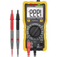
The PAN 3000A+ is an intelligent, flexible current measuring plier. ±t can automatically detect incoming signals without the user having to select a measurement function or a measuring range.
Functions: Alternating current, alternating voltage, < voltage, frequency, resistance and continuity test
The technical progress is subject to change.
7. Scope of delivery
After6unpacking6please6check6the6package6contents6for6transport6damage6and6completeness.6
- Measurement6device6
- Test6leads6
- Battery(s)6
+. Operating6manual6
6
3. Safety Instructions
To6ensure6the6safe6use6of6the6device,6please6follow6all6the6safety6and6operating instructions6given6in6this6manual.6
6
- Before6 using6 the6 device, 6 make6 sure6 that6 test6 leads6 and6 the6 device6 are6 in6 good6 condition6 and6 the6 device6 is6 working6 properly6 (e.g. 6 by 6 connecting 6 to 6 known 6 voltage 6 sources). 6
- The6device6may6not6be6used6if6the6housing6or6the6test6leads6are6damaged, if6one6or6more6functions6are6not6working,6if6functions6are6not6displayed,6or if6you6suspect6that6something6is6wrong.6
- ±f6 the6 safety6 of6 the6 user6 cannot6 be6 guaranteed,6 the6 device6 may6 not6 be operated6and6secured6against6use.6
- While6using6this6device,6hold6the6test6leads6only6behind6the6finger6guards6-do6not6touch6the6probes.6
- Never6 ground6 yourself6 while6 making6 electrical6 measurements.6 Ωo6 not touch6any6exposed66metal6pipes,66fittings6etc.,66which6could6have66a66grou potential.6Ensure66that6your6body66is66isolated6by66using6dry66clothes,6rubb shoes,6rubber6mats6or6other6approved6insulation6materials.6
- Operate6the6device6in6a6way6that6it6is6not6difficult6to6operate6the6network separators.6
-
Never6 connect6 the6 device6 to6 voltage6 or6 current6 sources6 that6 exceed6 the6 specified6 maximum6 values.6
-
±f the battery symbol appears in the display, replace the battery immediately.
• Always switch off the appliance and remove the test leads from all voltage sources before opening the device to exchange the battery or the fuse. - Never use the device with the rear cover removed or with the battery and fuse compartment open!
• Ωo not use the device outdoors, in humid surroundings or in environments that are subjected to extreme temperature fluctuations.
• Ωo not store the device in places which are exposed to direct sunlight. - Remove the battery if the device is not used for a long time.
- ±f changes or modifications are made to the device, the operational safety is no longer guaranteed and the warranty becomes void.
8. Symbols Description
 | |
 | Risk of Ωanger. ±important information See instruction manual |
 | This product should not be disposed along with normal domestic waste at the end of its service life but should be handed over at a collection point for recycling electrical and electronic devices. |
 | Product is protected by double insulation |
 | Attention! Hazardous voltage. Risk of electric shock. |
| The device is designed for making measurements at sources of low voltage installations. Examples are meters and measurements on primary overload protection devices and ripple control devices. | |
 | Battery compartment |
 | >round / Earth (max. voltage to earth) |
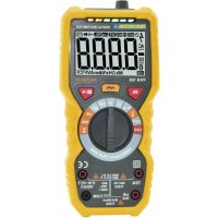
5. Panel Description
(Note %ig. 1)
- %flexible clamp
- <losure
-
Maindisplay / Sidedisplay (small numbers)
+. %unction keys
+.1 backlight
+.2 Ωata hold
+.3 Point ±Illumination -
Main switch
-
±nput terminal
6. Symbols of the Display
(Note %ig. 2)
A< A< voltage / current
< < voltage
Battery low

Operation indicator / Auto power off
Audible continuity test active
H Ωata hold
Ω Resistance measurement
Hz %frequency measurement
A A< <current measurement
V < Voltage measurement / A< Voltage measurement
OL Overload indicator
Sidedisplay (small numbers)
This device does not use all the symbols shown in the image.
7. General Specifications
Display LCD with backlight
3^3/_4 Digits (to 5999)
Overload indicator OL
Polarity automatically (minus sign for negative
polarity)
Measuring rate 3 / s
response time 0,5 s
Category CAT IV 600 V
max. voltage to earth 600 V
Continuity test If the resistance is < 50 , you hear an
audible signal.
Test current ca. 1 mA
Open circuit voltage ca. 0,8 V
Auto power off ca. 5 Min.
Internal impedance 2 MΩ
Power supply 3 x 1,5 V (AAA Battery(s))
Operating temperature 0 - 40°C (32 - 104°F) / < 80% Humidity
Altitude max. 2000 m
Storage temperature -10 - 60°C (14 - 140°F) (Remove the battery if
Humidity >80%
Weight 220 g (with Battery(s))
Dimensions 178 x 324 x 30 mm
| Function Range Resolution | Accuracy of the value displayed in % | |
| AC current (A)~40-65 Hz *)min. 0,1 A | 60 A 0,01 A | ±(1,5% + 5 digits)<10 A ±(2,0% + 10 d) |
| 600 A 0,1 A | ||
| 3000 A 1 A ±(2,0% + 5 digits) | ||
| AC current (A)~65 - 200 Hz *)min. 0,1 A | 60 A 0,01 A | ±(2,5% + 5 digits) |
| 600 A 0,1 A | ||
| 3000 A 1 A ±(3,0% + 5 digits) | ||
| AC current (A)~200 - 1000 Hz *)min. 0,1 A | 60 A 0,01 A | ±(3,0% + 5 digits)>1000 A Ωata not available |
| 600 A 0,1 A | ||
| 3000 A 1 A | ||
| AC voltage (V)~45 - 65 Hz *)min. 0,5 V | 6 V 0,001 V | ±(1,2% + 3 digits) 60 V 0,0 |
| 600 V 0,1 V | ||
| AC voltage (V)~40 - 2000 Hz *)(< 45 Hz, >65 Hz)min. 0,5 V | 6 V 0,001 V | ±(2,0% + 5 digits) |
| 60 V 0,01 V | ||
| 600 V 0,1 V | ||
| ΩC voltage (V)~min. 0,2 V | 6 V 0,001 V | ±(0,8% + 3 digits) 60 V 0,0 |
| 600 V 0,1 V | ||
| Frequency (Hz)AC current:min. 3 A /40 Hz - 1 kHzAC voltage:min. 0,5 V / 40 Hz - 10 kHz | 40 - 1000 Hz 0,1 Hz | ±(0,5% + 2 digits) |
| 1 kHz-10kHz 1 Hz | ||
| Resistance (Ω) | 6 kΩ 0,001 k Ω | ±(1% + 3 digits) |
| 60 kΩ 0,01 k Ω | ||
| 600 kΩ 0,1 k Ω | ||
| 6 M Ω 0,001 M Ω | ||
*) The data for other frequencies is currently unavailable.
Precision depending on position
(Note Fig. 3)
| Measuring position Ωeviation |
| A 35 mm ±0.5% |
| B 50 mm ±1.5% |
| C 60 mm ±2.0% |
| Ω >60 mm ±5.0% |
8. Operating Instructions
General information
Always switch OFF the device when it is not in use.
Please refer to the sketches on the first pages of this manual.
To switch the unit on or off, press the main switch (5) until a short beep is heard.
Attention!
Avoid voltage measuring in electrical circuits while motors are switched on or off. The stress-spikes can damage the instrument.
Hazardous voltage! The probes may not be long enough to touch the hot parts in some 230V wall sockets as they are deep inside. As a result, the reading can show 0 volts. Make sure that the probes touch the metallic contacts in the socket before assuming that voltage has not been applied.
Ωdevices like welding transformer, car ignition system, etc. could produce stray electromagnetic fields which could adulterate the result of a measurement.
Automatic/Manual1Range1selection1
When the meter is switched on, it is in the auto ranging mode. The device automatically detects the appropriate measuring range. Manual range selection is not possible.
Data1hold1
±f the reading could not be read during measurement due to difficult operation the „HOLΩ“-button (+.2) could be pressed to freeze the display reading. Press the „HOLΩ“-button to freeze the display reading. The "H" symbol appears in the display. Press the „HOLΩ“-button again to return to standard operation.
Backlight1
To turn the backlight on or off, press the button (+.1).
Point1Illumination1
±n low light conditions, you can illuminate the point. To do this, press the button (+.3).
Auto1power1off1
±f no further measurements are carried out, the device switches off automatically after 5 minutes.
DC1Voltage1measurement61AC1Voltage1measurement61Resistance1measurement1and1Continuity1test1
The device detects < voltage, alternating voltage or resistance automatically. Alternating current is detected via the flexible pliers.
(Sequence: A< voltage, Ω< voltage, A< current, resistance / continuity test)
Ω< voltage: ±f the polarity is reversed a "-" is displayed.
A< voltage / current: When measuring alternating voltage/alternating current, the frequency is displayed in the secondary display.
Resistance / Continuity test: If the resistance is < 50 , you hear an audible signal.
- Switch the unit on with the main switch (5).
- Attach the pin-plug of the black test lead to the COM-jack and the pin-plug of the red test lead to the V-, Ω-jack.
- Touch the measuring points with the probe tips.
- Once the reading stabilizes, read the value.
AC1Current1measurement1
Alternating current measurements are only carried out via the flexible pliers. DC measurements are not possible.
Always measure current on one conductor only. Covering more than one conductor results in measuring differential current (like identifying leakage current). To avoid measuring errors related to other hot conductors, please observe maximum phase-to-phase clearance.
After a current measurement, it takes a few seconds for the display to return to zero. This effect results from the true RMS function and is normal.
- Switch the unit on with the main switch (5).
- You open the flexible clamp by turning the bolt (2).
- Clamp the wire placed in the opening and close the flexible clamp again.
- Once the reading stabilizes, read the value.
With simultaneous measurement of alternating current via the flexible pliers and voltage (AC/DC) or resistance via the connection sockets, the secondary display shows the current instead of the frequency and in the main display the voltage or the resistance.
(Note Fig. 4)
9. Maintenance
Only6authorized6service6technicians6may6repair6the6instrument.6
6
Changing the battery(s)
Replace6the66battery(s)66when66the66battery66symbol66or66BATT66is66displayed6L<Ω.6
6
- Open6the6battery6compartment.6
- Replace6the6battery.6Mind6the6correct6polarity.6
- <lose6the6battery6compartment.6
+. Ωisposal6of6the6flat6battery6should6meet6environmental6standards.6
6
Remove6the6battery6if6the6device6is6not6used6for6a6long6time.6
6
Cleaning
±f6the6instrument6is6dirty6after6daily6usage,66it6is66advised6to6clean6it66by6using humid66cloth66and66a66mild66household66detergent.66Prior66to66cleaning,66ensun instrument6is6switched6off6and6disconnected6from6external6voltage6supply6and6 any6other6instruments6connected.6Never6use6acid6detergents6or6dissolvent6for6 cleaning.6
6
10. Guarantee and Spare Parts
6
PAN<ONTROL66instruments66are66subject66to66strict66quality66control.66However, should6the6instrument6function6improperly6during6daily6use,6your6are6protected6 by6a62+6months6warranty6from6the6date6of6purchase6(valid6only6with6invoice).6
Only trained technicians may carry out repairs to this device. ±n case of spare part requirement or in case of queries or problems, please get in touch with your vendor or:
KRYSTUFEK.at
Dipl.Ing. Ernst KRYSTUFEK GmbH & Co KG
Error and misprints reserved.
2017-11


DC -tension continue
%ile faible
A Meting wisselstroom
| Mätposition Avvikelse |
| A 35 mm ±0.5% |
| B 50 mm ±1.5% |
| C 60 mm ±2.0% |
| D >60 mm ±5.0% |
8. Användning
Allmän information
- INDEX
- Introduction
- Scope of delivery
- Safety Instructions
- Symbols Description
- Panel Description
- (Note %ig. 1)
- Symbols of the Display
- General Specifications
- Precision depending on position
- Operating Instructions
- General information
- Attention!
- Automatic/Manual1Range1selection1
- Data1hold1
- Backlight1
- Point1Illumination1
- Auto1power1off1
- DC1Voltage1measurement61AC1Voltage1measurement61Resistance1measurement1and1Continuity1test1
- AC1Current1measurement1
- Maintenance
- Changing the battery(s)
- Cleaning
- Guarantee and Spare Parts
- KRYSTUFEK.at
- Användning
- Allmän information
Brand : Pancontrol
Model : PAN 3000A+ True RMS
Category : Measuring equipment