
PAN 200A+ - Measuring equipment Pancontrol - Free user manual and instructions
Find the device manual for free PAN 200A+ Pancontrol in PDF.
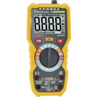
| Product Type | Smart Digital Clamp Meter |
| Brand | Pancontrol |
| Model | PAN 200A+ |
| Power Supply | 2 AAA 1.5V batteries |
| Display | 3 3/4 digit LCD (5999) with backlight |
| Overvoltage Category | CAT III 600 V |
| Max. Voltage to Ground | 600 V |
| AC Current Measurement | Up to 200 A, resolution 0.01 A, accuracy ±(2.5% + 8 digits) |
| AC Voltage Measurement | Up to 600 V, resolution 0.1 V, accuracy ±(0.8% + 5 digits) |
| DC Voltage Measurement | Up to 600 V, resolution 0.1 V, accuracy ±(0.5% + 3 digits) |
| Frequency Measurement (Current) | Up to 1000 Hz, resolution 0.1 Hz, accuracy ±(1.0% + 5 digits) |
| Frequency Measurement (Voltage) | Up to 1000 Hz, resolution 0.1 Hz, accuracy ±(1.0% + 5 digits) |
| Resistance Measurement | Up to 6 kΩ, resolution 0.001 kΩ, accuracy ±(0.8% + 3 digits) |
| Continuity Test | Audible signal below 50 Ω |
| Non-Contact Voltage Tester (NCV) | Threshold >90 V, audible and visual alarm |
| Special Functions | Data hold (HOLD), backlight, auto power off, auto ranging |
| Operating Conditions | 18 - 28 °C, humidity <75% |
| Dimensions | Not specified (estimated: approx. 200x70x30 mm) |
| Weight | Not specified (estimated: approx. 250 g with batteries) |
| Maintenance and Cleaning | Damp cloth with mild detergent; do not use solvents |
| Safety | Double insulation, CE compliant (EN-61010) |
| Warranty | 2 years legal warranty from purchase date |
Frequently Asked Questions - PAN 200A+ Pancontrol
User questions about PAN 200A+ Pancontrol
0 question about this device. Answer the ones you know or ask your own.
Ask a new question about this device
Download the instructions for your Measuring equipment in PDF format for free! Find your manual PAN 200A+ - Pancontrol and take your electronic device back in hand. On this page are published all the documents necessary for the use of your device. PAN 200A+ by Pancontrol.
USER MANUAL PAN 200A+ Pancontrol
- Introduction ...... 2
- Scope of delivery....3
- Safety Instructions .... 3
- Symbols Description ....4
- =anel Description ....5
- Symbols of the Display ....6
- General Specifications ....7
- Operating Instructions .....9
- Maintenance 12
- Guarantee and Spare =arts 13
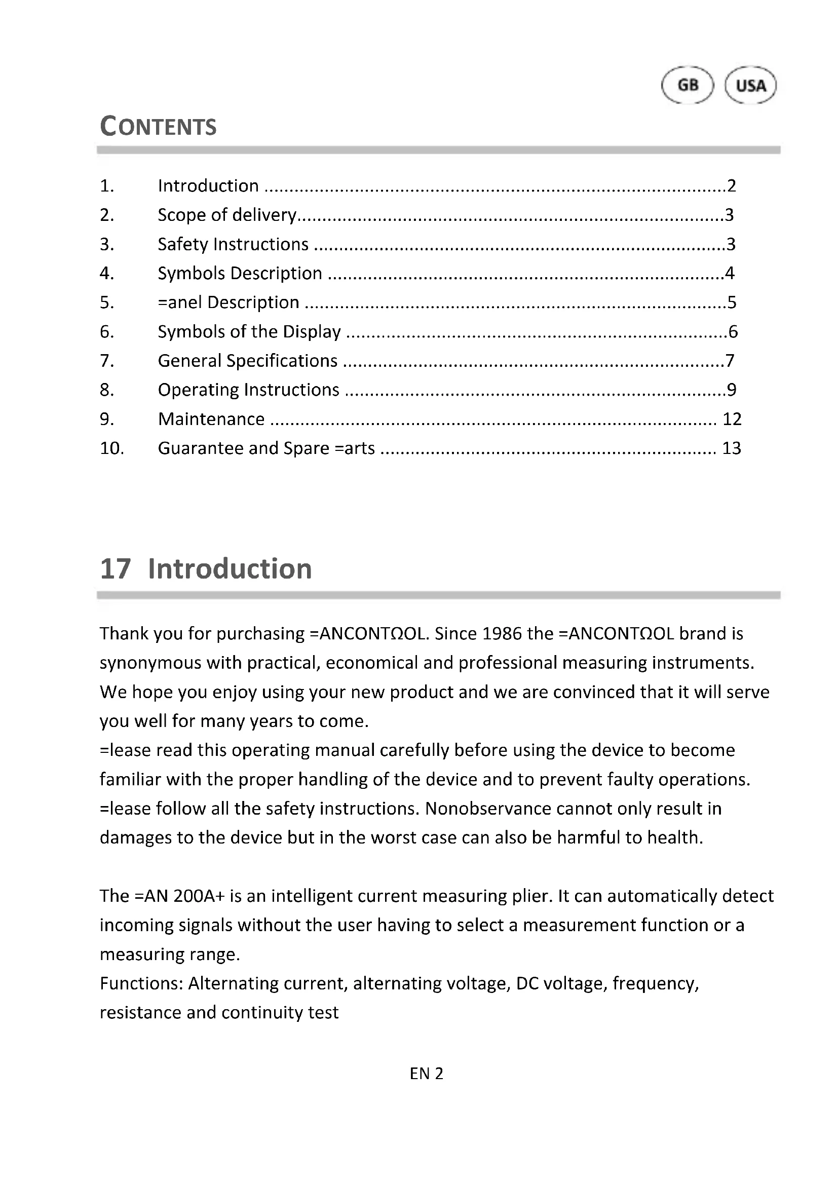
17 Introduction
Thank you for purchasing =ANCONTΩOL. Since 1986 the =ANCONTΩOL brand is synonymous with practical, economical and professional measuring instruments. We hope you enjoy using your new product and we are convinced that it will serve you well for many years to come.
=lease read this operating manual carefully before using the device to become familiar with the proper handling of the device and to prevent faulty operations. =lease follow all the safety instructions. Nonobservance cannot only result in damages to the device but in the worst case can also be harmful to health.
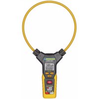
The =AN 200A+ is an intelligent current measuring plier. It can automatically detect incoming signals without the user having to select a measurement function or a measuring range.
Functions: Alternating current, alternating voltage, DC voltage, frequency, resistance and continuity test
6
The6technical6progress6is6subject6to6change.6
6
27 Scope of delivery
After6unpacking6please6check6the6package6contents6for6transport6damage6and6completeness.6
• Measurement6device6
- Test6leads6
- Battery(s)6
- Operating6manual6
6
37 Safety Instructions
To66ensure66the66safe66use66of66the66device,66please66follow66all66the66safety66instructions6given6in6this6manual.6
6
- Before6 using6 the6 device, 6 make6 sure6 that6 test6 leads6 and6 the6 device6 are6 in6 condition6 and6 the6 device6 is6 working6 properly6 (e.g. 6 by6 connecting6 to6 k voltage6 sources). 6
- The6device6may6not6be6used6if6the6housing6or6the6test6leads6are6damaged,6i or6 more6 functions6 are6 not6 working,6 if6 functions6 are6 not6 displayed,6 suspect6that6something6is6wrong.6
- %f6the6safety6of6the6user6cannot6be6guaranteed,6the6device6may6not6be6ope and6secured6against6use.6
- While6using6this6device,6hold6the6test6leads6only6behind6the6finger6guards6-6d touch6the6probes.6
- Never6ground6yourself6while6making6electrical6measurements.6Do6not6touch6andexposed6metal6pipes,6fittings6etc.,6which6could66have6a66ground6potential.6Ensthat66your66body66is66isolated66by66using66dry66clothes,66rubber66shoes,66rubother6approved6insulation6materials.6
-
Operate6 the6 device6 in6 a6 way6 that6 it6 is6 not6 difficult6 to6 operate6 the separators.6
-
Never connect the device to voltage or current sources that exceed the specified maximum values.
- %f the battery symbol appears in the display, replace the battery immediately.
• Always switch off the appliance and remove the test leads from all voltage sources before opening the device to exchange the battery or the fuse. - Never use the device with the rear cover removed or with the battery and fuse compartment open!
- Do not use the device near strong magnetic fields (for e.g. welding transformer), as this can distort the display.
- Do not use the device outdoors, in humid surroundings or in environments that are subjected to extreme temperature fluctuations.
- Do not store the device in places which are exposed to direct sunlight.
- remove the battery if the device is not used for a long time.
- %f changes or modifications are made to the device, the operational safety is no longer guaranteed and the warranty becomes void.
47 Symbols Description
| CE | Conforms to the relevant European Union directive (EN-61010) |
| Ωisk of Danger. %important information See instruction manual | |
| This product should not be disposed along with normal domestic waste at the end of its service life but should be handed over at a collection point for recycling electrical and electronic devices. | |
| =roduct is protected by double insulation | |
| Attention! Attention: The device is designed for making measurements in building installations. Examples are measurements on junction boards, circuit breakers, wiring, switches, permanently installed sockets, devices for industrial use as well as permanently installed motors. | |
| CAT %%% | |
| A AC current | |
| V AC voltage | |
| <z Frequency | |
| V DC voltage | |
| Ω | Ωesistance |
| Continuity test | |
| Battery compartment | |
| Ground / Earth (max. voltage to earth) | |
57 Panel Description
(Note Fig. 1)
- %nduction clamp
- Clamp opener
- Display
+. %nput terminal
+.1 General jack (V, Ω)
+.2 >oint connector (COM)
- Function keys
5.1 Data hold / Backlight
5.2 Frequency measurement / Non Contact Voltage tester (NCV)
- Main switch
- NCV - Sensor
- NCV - =ower indicator
67 Symbols of the Display
(Note Fig. 2)
- AC AC voltage / current
- DC DC voltage
- Battery low
- Operation indicator / Auto power off
- Audible continuity test active
- H Data hold
- Ω Resistance measurement
-
Hz Frequency measurement
-
A AC Current measurement
- V DC Voltage measurement / AC Voltage measurement
- NCV Non Contact Voltage tester (NCV) active
- OL Overload indicator
This device does not use all the symbols shown in the image.
7. General Specifications
Display LCD with Backlight
3 3/4 Digits (to 5999)
Overload indicator OL
Polarity automatically (minus sign for negative
polarity)
Measuring rate 3x / Second
Category CAT III 600 V
max. voltage to earth 600 V
Continuity test If the resistance is less than about 50 Ω, you
hear an audible signal. If the circuit is open, the display shows "OL".
Auto power off ca. 10 Min.
Power supply 2 x 1,5 V (AAA Battery(s))
Operating temperatute 18 - 28°C (64 - 82°F) / <75% Humidity
Temperature coefficient < 0,1 x Accuracy / °C
Altitude max. 2000 m
Storage temperature -10 - 50°C (14 - 122°F) (Ωemove the battery if
Humidity >80%)
Ωecalibration 1 x yearly (under Operating temperature)
| Function Ωange | Ωesolutic n | Accuracy of the value displayed in % |
| AC current (A)~40-65 Hz min. 0,01 A | 6 A 0,001 A | ±(2,5% + 8 digits) *) 60 A 0,1 V |
| 200 A 0,1 A | ||
| AC voltage (V)~45 - 65 Hz min. 1,0 V | 600 V 0,1 V | ±(0,8% + 5 digits) *) |
| DC voltage (V)~min. 0,5 V | 600 V 0,1 V | ±(0,5% + 3 digits) |
| Frequency Current (Hz) Measurement via Induction clamp (min 0,2 A)~ | 60 Hz 0,1 Hz | ±(1,0% + 5 digits) *) |
| 1000 Hz 1 Hz | ||
| Frequency Voltage (Hz) Measurement via Input terminal (min 0,2 V)~ | 60 Hz 0,1 Hz | ±(1,0% + 5 digits) *) |
| 1000 Hz 1 Hz | ||
| Ωesistance (Ω) 6 kΩ 0,001 kΩ | ±(0,8% + 3 digits) |
*) The data for other frequencies is currently unavailable.
Accuracy is valid for one year from the last calibration.
8. Operating Instructions
General information
Always switch OFF the device when it is not in use.
=lease refer to the sketches on the first pages of this manual.
To switch the unit on or off, press the main switch (6) for about 2 seconds.
Attention!
Avoid voltage measuring in electrical circuits while motors are switched on or off. The stress-spikes can damage the instrument.
<azardous voltage! The probes may not be long enough to touch the hot parts in some 230V wall sockets as they are deep inside. As a result, the reading can show 0 volts. Make sure that the probes touch the metallic contacts in the socket before assuming that voltage has not been applied.
Devices like welding transformer, car ignition system, etc. could produce stray electromagnetic fields which could adulterate the result of a measurement.
Data hold
%f the reading could not be read during measurement due to difficult operation the „<OLD"-button (5.1) could be pressed to freeze the display reading.
- =ress the „<OLD"-button to freeze the display reading.
- The display shows the "<"-symbol to indicate the activated <OLD function.
- =ress the „<OLD"-button again to return to standard operation.
Backlight
To turn the backlight on or off, press for two seconds the button (5.1).
Automatic/Manual Range selection
When the meter is switched on, it is in the auto ranging mode. The device automatically detects the appropriate measuring range. Manual range selection is not possible.
Auto power off
If no further measurements are carried out, the device switches off automatically after 10 minutes.
Non Contact Voltage tester 6NCV)
• To turn on the NCV function, press the NCV key (5.2) for two seconds. The NCV symbol appears on the display.
- ±eep the tip of the measuring device to a power outlet or a cable and press the NCV key. In the presence of dangerous voltage, (>90 V) a signal tone sounds and the LED indicator lights up.
- Even without an alarm, dangerous voltage can be concerned! This depends on various factors. Therefore, if necessary, check the zero voltage with the voltmeter.
- No other measurements are possible in NCV mode.
AC Current measurement and Frequency measurement 6Current)
Alternating current measurements are only carried out via the pliers. DC measurements are not possible.
Always measure current on one conductor only.
Covering more than one conductor results in measuring differential current (like identifying leakage current). To avoid measuring errors related to other hot conductors, please observe maximum phase-to-phase clearance.
- Press the lever to open the induction jaw.
-
Place the wire in the center of the pliers opening as far as possible and close the measuring pliers again.
-
If the current level is >0.01 A, the current is displayed.
- Press the Hz key (5.2) - If the current level is >0.2 A, the frequency is displayed.
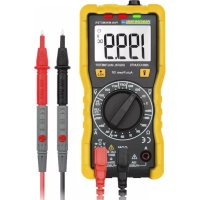
AC Voltage measurement and Frequency measurement 6Voltage)
- Attach the pin-plug of the black test lead to the COM-jack and the pin-plug of the red test lead to the general jack (V, Ω).
- Touch the measuring points with the probe tips.
- The device detects DC voltage, alternating voltage or resistance automatically. Alternating current is detected via the pliers.
- If the input signal is >=1.0 ~V AC , the voltage is displayed. (V\~) An input signal of <1.0 ~V AC indicates the resistance. (Ω)
- Press the Hz key (5.2) - If the voltage is > 1,0 V, the frequency is displayed.
• Once the reading stabilizes, read the value.
DC Voltage measurement
- Attach the pin-plug of the black test lead to the COM-jack and the pin-plug of the red test lead to the general jack (V, Ω).
- Touch the measuring points with the probe tips.
- The device detects DC voltage, alternating voltage or resistance automatically. Alternating current is detected via the pliers.
- If the input signal is >=0.5 V, the voltage is displayed. (V=) An input signal of <0.5 V indicates the resistance. ( )
- Once the reading stabilizes, read the value.
- If the polarity is twisted a "Minus sign" is displayed.
Resistance measurement
- Attach the pin-plug of the black test lead to the COM-jack and the pin-plug of the red test lead to the general jack (V, Ω).
- Touch the measuring points with the probe tips.
• Once the reading stabilizes, read the value.
9. Maintenance
Only6authorized6service6technicians6may6repair6the6instrument.66
Changing the battery(s)
Ωeplace6the6battery(s)6when6the6battery6symbol6or6BATT6is6displayed6on6the6LC
- Open6the6battery6or6fuse6compartment6with6a6suitable6screwdriver.6
- Ωeplace6the6battery.6Mind6the6correct6polarity.6
- Close6the6battery6compartment.6
- Disposal6of6the6flat6battery6should6meet6environmental6standards.6 Ωemove6the6battery6if6the6device6is6not6used6for6a6long6time.6 6
Cleaning
%f6the6instrument6is6dirty6after6daily6usage,6it6is6advised6to6clean6it6by6using6a cloth6and6a6mild6household6detergent.6=rior6to6cleaning,6ensure6that6instrument6 switched66off66and66disconnected66from66external66voltage66supply66and66any66 instruments6connected.6Never6use6acid6detergents6or6dissolvent6for6cleaning.6
6
6
=ANCONTΩOL instruments are subject to strict quality control. <however, should the instrument function improperly during daily use, your are protected by a 2+ months warranty from the date of purchase (valid only with invoice).
Only trained technicians may carry out repairs to this device. %n case of spare part requirement or in case of queries or problems, please get in touch with your vendor or:
KRYSTUFEK.at
Dipl.Ing. Ernst KRYSTUFEK GmbH & Co KG AUSTRIA, A-1230 Wien, Pfarrgasse 79 Tel +43 1 616 40 10, Fax +43 1 616 40 10-21 office@krystufek.at, www.krystufek.at
Error and misprints reserved.
2017-11
- DC >ension continue
- Pile faible
Mesure tension continue
u
Non-contact spanning tester (NCV5
Non-contact tensiune tester (NCV)
- Introduction
- Scope of delivery
- Safety Instructions
- Symbols Description
- Panel Description
- (Note Fig. 1)
- Symbols of the Display
- (Note Fig. 2)
- General Specifications
- Operating Instructions
- General information
- Attention!
- Data hold
- Backlight
- Automatic/Manual Range selection
- Auto power off
- Non Contact Voltage tester 6NCV)
- AC Current measurement and Frequency measurement 6Current)
- AC Voltage measurement and Frequency measurement 6Voltage)
- DC Voltage measurement
- Resistance measurement
- Maintenance
- Changing the battery(s)
- Cleaning
- Mesure tension continue
- Non-contact spanning tester (NCV5
- Non-contact tensiune tester (NCV)
Brand : Pancontrol
Model : PAN 200A+
Category : Measuring equipment