
PAN 185 - Multimeter Pancontrol - Free user manual and instructions
Find the device manual for free PAN 185 Pancontrol in PDF.
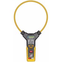
| Product type | Digital multimeter |
| Brand | Pancontrol |
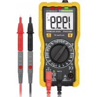
| Model | PAN 185 |
| Dimensions (L × W × H) | 204 × 94 × 57 mm |
| Weight (with batteries) | Approx. 410 g |
| Power supply | 4 × 1.5 V AA batteries |
| Display | 3 1/2 digits (3999 counts) |
| Overvoltage category | CAT III 1000 V / CAT IV 600 V |
| Max. voltage to earth | 1000 V DC / 750 V AC |
| Input impedance | 10 MΩ |
| Measurement functions | AC/DC voltage, AC/DC current, resistance, frequency, capacitance, temperature (type K), sound level, light intensity, diode test, continuity, humidity, ambient temperature |
| Overload protection | Yes |
| Fuse | FF 400 mA H 1000 V (for µA/mA) |
| Auto power off | After 10 minutes |
| Included accessories | Test leads, type K temperature probe, batteries, padded carrying case, instruction manual |
| Warranty | 2 years legal |
| Cleaning | Damp cloth, no solvents |
| Standards | CE, EN-61010, double insulation |
| Operating conditions | 0°C to 40°C, <70% RH |
| Storage conditions | -10°C to 60°C, <70% RH |
Frequently Asked Questions - PAN 185 Pancontrol
User questions about PAN 185 Pancontrol
0 question about this device. Answer the ones you know or ask your own.
Ask a new question about this device
Download the instructions for your Multimeter in PDF format for free! Find your manual PAN 185 - Pancontrol and take your electronic device back in hand. On this page are published all the documents necessary for the use of your device. PAN 185 by Pancontrol.
USER MANUAL PAN 185 Pancontrol
- Introduction 2
- Scope of delivery 3
- Safety Instructions.. 3
- Symbols Description 5
- Panel Description 6
- Symbols of the Display 7
- General Specifications 9
- Operating Instructions 12
- Maintenance 16
- Guarantee and Spare Parts 18
1. Introduction
Thank you for purchasing PANCONTROL. Since 1986 the PANCONTROL brand is synonymous with practical, economical and professional measuring instruments. We hope you enjoy using your new product and we are convinced that it will serve you well for many years to come.
Please read this operating manual carefully before using the device to become familiar with the proper handling of the device and to prevent faulty operations. Please follow all the safety instructions. Nonobservance cannot only result in damages to the device but in the worst case can also be harmful to health.
2. Scope of delivery
After unpacking please check the package contents for transport damage and completeness.
- Measurement device
- Test leads
- Type K temperature probe
Battery(s) - Protective cover
- Operating manual
3. Safety Instructions
To ensure the safe use of the device, please follow all the safety and operating instructions given in this manual.
- Before using the device, make sure that test leads and the device are in good condition and the device is working properly (e.g. by connecting to known voltage sources).
- The device may not be used if the housing or the test leads are damaged, if one or more functions are not working, if functions are not displayed, or if you suspect that something is wrong.
- If the safety of the user cannot be guaranteed, the device may not be operated and secured against use.
- While using this device, hold the test leads only behind the finger guards - do not touch the probes.
- Never ground yourself while making electrical measurements. Do not touch any exposed metal pipes, fittings etc., which could have a ground
potential. Ensure that your body is isolated by using dry clothes, rubber shoes, rubber mats or other approved insulation materials.
-
Operate the device in a way that it is not difficult to operate the network separators.
-
Always adjust the rotary switch to the desired measuring range before starting the measurement and engage the switch in the proper measuring range.
-
If the magnitude of the signal to be measured is not known, always start with the highest measuring range on the rotary switch and then reduce step-by-step.
-
If the measuring range needs to be changed during the measurement, remove the probes from the circuit first.
-
Never turn the rotary switch during measurement, but always in the disconnected condition.
-
Never connect the device to voltage or current sources that exceed the specified maximum values.
-
Disconnect the power supply and discharge the filter capacitors in the power supply before measuring resistance or testing diodes.
-
Never connect the test leads of the device to a voltage source, if the rotary switch is set to measure current, resistance or test diodes. This can damage the device.
-
If the battery symbol appears in the display, replace the battery immediately.
-
Always switch off the appliance and remove the test leads from all voltage sources before opening the device to exchange the battery or the fuse.
-
Never use the device with the rear cover removed or with the battery and fuse compartment open!
-
Do not use the device near strong magnetic fields (for e.g. welding transformer), as this can distort the display.
-
Do not use the device outdoors, in humid surroundings or in environments that are subjected to extreme temperature fluctuations.
- Do not store the device in places which are exposed to direct sunlight.
- Remove the battery if the device is not used for a long time.
- If changes or modifications are made to the device, the operational safety is no longer guaranteed and the warranty becomes void.
4. Symbols Description
Conforms to the relevant European Union directive (EN-61010)
回
Product is protected by double insulation
Risk of Danger. Important information See instruction manual
Attention! Hazardous voltage. Risk of electric shock.

This product should not be disposed along with normal domestic waste at the end of its service life but should be handed over at a collection point for recycling electrical and electronic devices.
CAT III
The device is designed for making measurements in building installations. Examples are measurements on junction boards, circuit breakers, wiring, switches, permanently installed sockets, devices for industrial use as well as permanently installed motors.
CAT IV
The device is designed for making measurements at sources of low voltage installations. Examples are meters and measurements on primary overload protection devices and ripple control devices.
\~
AC voltage / current (AC)
一
DC voltage / current (DC)

AC/DC
Battery compartment
Ground / Earth (max. voltage to earth)
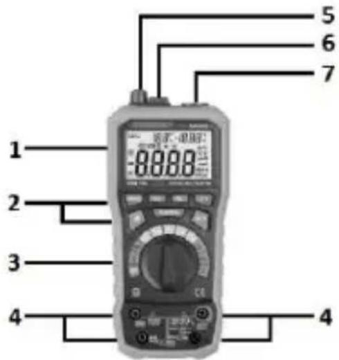
5. Panel Description
- Display
- Function keys
- Rotary switch
- Input terminal
- Illuminance level - Sensor
- Temperature / Humidity - Sensor
- Noise level - Sensor (microphone)
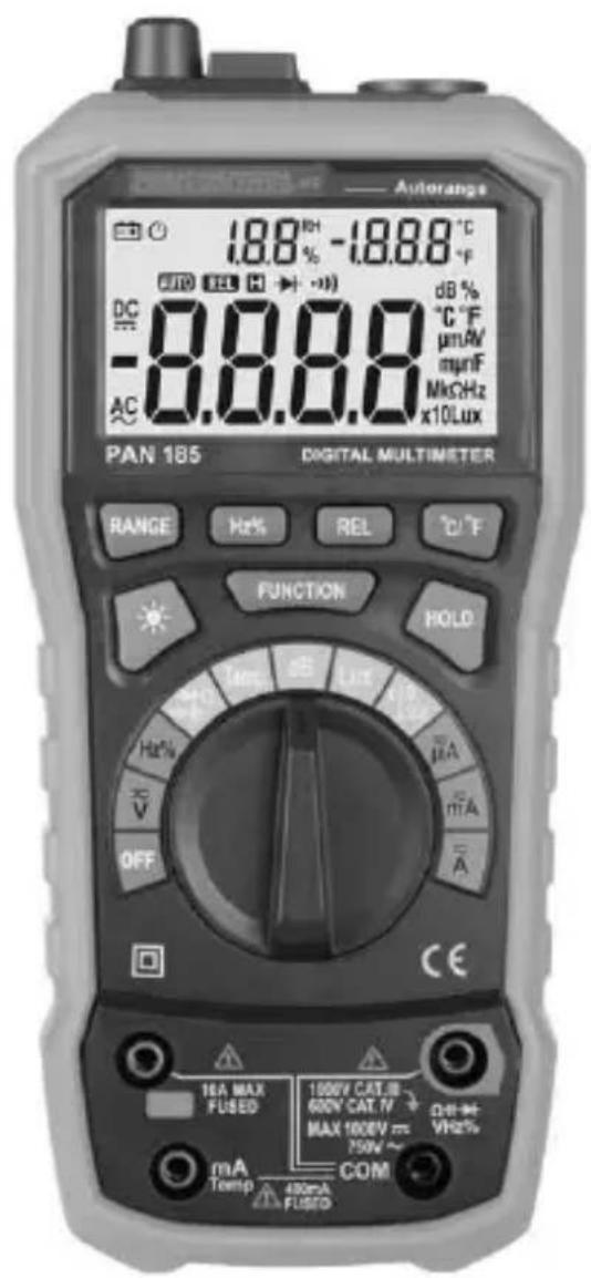
Function keys
RANGE Automatic/Manual Range selection
Hz / % Frequency / Duty-cycle
REL Relative mode (REL)
^ C / ^ Set temperature unit

backlight
FUNCTION Function
HOLD Data hold
Symbols of the rotary switch
| OFF | Device switched OFF |
| V~ | DC Voltage measurement / AC Voltage measurement |
| Hz % | Frequency measurement and Duty cycle |
| →←→)Ω← | Diode testing / Continuity test / Resistance measurement / Capacity measurement |
| TEMP | Temperature measurement |
| dB | Noise level measurement |
| Lux / x10 Lux | Luminance intensity measurement |
| μA mA ~A~ | DC current measurement / AC Current measurement |
6. Symbols of the Display
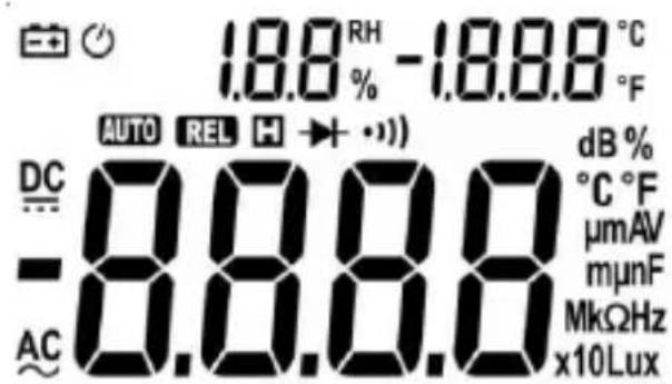
- AC AC voltage / current
-
DC DC voltage / current
Battery low
Operation indicator / Auto power off -
tomatic range selection active
- Diode test active
Audible continuity test active
Data hold relative - Resistance measurement
- Hz / % Frequency measurement and Duty cycle
- ^ C / ^ F Temperature measurement (Type K temperature probe)
dB Noise level measurement - Lux Luminance intensity measurement
- A DC current measurement / AC Current measurement
- V DC Voltage measurement / AC Voltage measurement
- F Capacity measurement
- OL Overload indicator
- Sidedisplay (Small numbers): Humidity (RH in %) Ambient temperature(°C or °F)
7. General Specifications
| Maindisplay | 3 1/2 Digits (to 3999) |
| Sidedisplay | Ambient temperature and Humidity |
| Overload indicator | OL |
| Polarity | automatically (minus sign for negative polarity) |
| Measuring rate | 3 / s |
| Category | CAT III 1000 V or CAT IV 600 V |
| max. voltage to earth | 1000 V DC / 750 V AC |
| Overload protection | 1000 V |
| Internal impedance | 10 MΩ |
| Diode test | Open circuit voltage: 1,5 V |
| Test current: <1 mA | |
| Continuity test | If the resistance is less than about 50 Ω, you hear an audible signal. If the circuit is open, the display shows “OL”. |
| Power supply | 4 x 1,5 V (AA) Battery(s) |
| Auto power off | 10 Min. |
| Operating temperature | 0° C to 40° C / <70% Humidity |
| Storage temperature | -10° C to 60° C / <70% Humidity (Remove the battery if Humidity >70%) |
| Fuse(s) | mA, μA -Range: FF 400 mA H 1000 V |
| A-Range: FF 10 A H 1000 V | |
| Weight | ca.410 g (with Battery(s)) |
| Dimensions | 204 x 94 x 57 mm |
| Function | Range | Resolution | Accuracy of the value displayed in % |
| DC voltage (V=) | 400 mV | 0,1 mV | ±(0,7% + 2 digits) |
| 4 V | 1 mV | ||
| 40 V | 10 mV | ||
| 400 V | 100 mV | ||
| 1000 V | 1 V | ||
| AC voltage (V~) | 400 mV | 0,1 mV | ±(0,8% + 3 digits) |
| 4 V | 1 mV | ||
| 40 V | 10 mV | ||
| 400 V | 100 mV | ||
| 750 V | 1 V | ±(1,0% + 3 digits) | |
| DC current (A=) | 400 μA | 0,1 μA | ±(1,2% + 3 digits) |
| 4 mA | 0,001 mA | ||
| 40 mA | 0,01 mA | ||
| 400 mA | 0,1 mA | ||
| 4 A | 0,001 A | ±(2,0% + 10 digits) | |
| 10 A | 0,01 A | ||
| AC current (A~) | 400 μA | 0,1 μA | ±(1,5% + 5 digits) |
| 4 mA | 0,001 mA | ||
| 40 mA | 0,01 mA | ||
| 400 mA | 0,1 mA | ||
| 4 A | 0,001 A | ±(3,0% + 10 digits) | |
| 10 A | 0,01A | ||
| Resistance (Ω) | 400 Ω | 0,1 Ω | ±(1,2% + 2 digits) |
| 4 kΩ | 0,001 kΩ | ||
| 40 kΩ | 0,01 kΩ | ||
| 400 kΩ | 0,1 kΩ | ||
| 4 MΩ | 0,001 MΩ | ||
| 40 MΩ | 0,01 MΩ | ±(2,0% + 5 digits) | |
| Frequency (Hz) | 9,999 Hz | 0,001 Hz | ±(2,0% + 5 digits) |
| 99,99 Hz | 0,01 Hz | ±(1,5% + 5 digits) | |
| 999,9 Hz | 0,1 Hz | ||
| 9,999 kHz | 0,001 kHz | ||
| 99,99 kHz | 0,01 kHz | ±(2,0% + 5 digits) | |
| 199,9 kHz | 0,1 kHz | ||
| >200 kHz | Indicative value | ||
| Duty-cycle (%) | 0,1 - 99,9% | 0,10% | ±3,0% |
| Capacitance (F) | 40 nF | 0,01 nF | ±(3,0% + 3 digits) |
| 400 nF | 0,1 nF | ||
| 4 μF | 0,001 μF | ||
| 40 μF | 0,01 μF | ||
| 100 μF | 0,1 μF | ||
| Temperature (Type K temperature probe - °C) | -20 ... 1000 °C | 1 °C | ±(1,0% + 3 digits) |
| Temperature (Type K temperature probe - °F) | -4 ... 1832 °F | 1 °F | ±(1,0% + 3 digits) |
| Ambient temperature (°C / °F) | 0 ... 40 °C | 0,1 °C | ±2 °C |
| 32 ... 104 °F | 0,1 °F | ±4 °F | |
| Humidity (%) | 20 ... 95 % | 0,10% | ±5 % |
| Noise level (dB) | 40 ... 100 dB | 0,1 dB | ±3,5% (94 dB 1 kHz sin.) |
| Illuminance level (Lux) (x10 Lux) | 4000 Lux | ±(5,0% + 10digits) | |
| 40000 Lux |
8. Operating Instructions
-
Always switch OFF the device when it is not in use.
-
If "OL" is displayed while measuring the value exceeds the used range. Switch to a higher range if available.
Attention!
Due to the high sensitivity the reading sometimes shows random values if the test leads are not connected to any signal. The reading stabilizes when the test leads are connected to the circuit to be tested.
Avoid voltage measuring in electrical circuits while motors are switched on or off. The stress-spikes can damage the instrument.
Hazardous voltage! The probes may not be long enough to touch the hot parts in some 230V wall sockets as they are deep inside. As a result, the reading can show 0 volts. Make sure that the probes touch the metallic contacts in the socket before assuming that voltage has not been applied.
Devices like welding transformer, car ignition system, etc. could produce stray electromagnetic fields which could adulterate the result of a measurement.
Automatic/Manual Range selection
If the instrument is switched on it is usually in automatic mode. "Auto range" is displayed. The instrument hereby automatically detects the most suitable range. In most cases this position fits your needs. If you need to manually select the range proceed as following:
-
By pressing the "RANGE"-button you can select the range manually:
-
Press RANGE as often as needed to get to the desired range.
-
To turn on the automatic range selection again, press the RANGE button for 2 seconds.
DC Voltage measurement / AC Voltage measurement
Attention!
DC voltage max. 1.000 V
AC voltage max. 750 V
- Set the rotary switch to the position V
- Attach the pin-plug of the black test lead to the COM-jack and the pin-plug of the red test lead to the V, , Hz %-jack.
- Connect the black test prod to the negative pole and the red test prod to the positive pole of the circuit to be tested.
- Once the reading stabilizes, read the value. If the polarity is twisted a "Minus sign" is displayed. Use the HOLD function if the reading is difficult to read.
DC current / AC Current measurement
Avoid current measurements with the 10A setting for more than 30 seconds. This can damage the device and / or the test leads.
- For measurements up to 4000mA set the rotary switch to the mA-Position and attach the pin-plug of the red test lead to the mA-jack. For measurements up to 10 A set the rotary switch to the A-Position and attach the pin-plug of the red test lead to the A-jack.
- Connect the black test prod to the negative pole and the red test prod to the positive pole of the circuit to be tested.
- Once the reading stabilizes, read the value. If the polarity is twisted a "Minus sign" is displayed. Use the HOLD function if the reading is difficult to read.
Resistance measurement
Before making any measurements, make sure the circuit is disconnected from any power source and all capacitors are properly discharged!
- Set the rotary switch to the position []
- Attach the pin-plug of the black test lead to the COM-jack and the pin-plug of the red test lead to the V, , Hz %-jack.
- Connect the black test prod to the negative pole and the red test prod to the positive pole of the circuit to be tested.
- Once the reading stabilizes, read the value. If the polarity is twisted a "Minus sign" is displayed. Use the HOLD function if the reading is difficult to read.
Continuity test
Before making any measurements, make sure the circuit is disconnected from any power source and all capacitors are properly discharged!
- Set the rotary switch to the position

- Attach the pin-plug of the black test lead to the COM-jack and the pin-plug of the red test lead to the V, , Hz-%-jack.
- Connect the black test prod to the negative pole and the red test prod to the positive pole of the circuit to be tested.
- If the resistance is less than about 50 you hear an audible signal. If the circuit is open, the display shows "OL".
Diode testing
- Set the rotary switch to the position

- Touch the diode to be tested with the probes. The forward voltage shows 400 to 700mV . The counter voltage shows "OL". Defective devices show a value about 0mV or "OL" in both polarities.
Frequency measurement and Duty cycle
- Set the rotary switch to the position Hz %
- Select with the FUNCTION button Hz or %
- Attach the pin-plug of the black test lead to the COM-jack and the pin-plug of the red test lead to the V, , Hz %-jack.
- Connect the black test prod to the negative pole and the red test prod to the positive pole of the circuit to be tested.
- Once the reading stabilizes, read the value. If the polarity is twisted a "Minus sign" is displayed. Use the HOLD function if the reading is difficult to read.
Capacity measurement

- Set the rotary switch to the position
- Attach the pin-plug of the black test lead to the COM-jack and the pin-plug of the red test lead to the V, , Hz %-jack.
- For capacitors with known polarity connect the red test lead with the anode and the black test lead with the cathode. Once the reading stabilizes, read the value. Use the HOLD function if the reading is difficult to read.
Relative mode (REL)
The relative measurement feature allows you to make measurements relative to a stored reference value. A reference voltage (current, etc.) can be stored
and following measurements can be compared to this value. The displayed value is the difference between the reference and the measured value.
- Perform the measurement as described above.
- Press REL to store the measured value as the reference value and the "REL" indicator appears on the display.
- Perform further measurements.
- The device displays the difference to the reference value.
- To return to normal mode, press the "REL" button for 2 seconds.
Temperature measurement (Type K temperature probe)
- Set the rotary switch to the position TEMP
- Connect the device to the K-probe. Observe the correct polarity!
- (Red: mA / TEMP, Black: COM)
- Connect the temperature probe to the device to be tested wait a few moments and read the value displayed. If necessary, use heat conducting paste.
Noise level measurement
- Set the rotary switch to the position dB
- Face the microphone detector to the sound source in a right angle.
- Strong wind (over 10m / s ) striking the microphone can cause misreading for measurement. A windscreen should be used in front of the microphone.
Luminance intensity measurement
- Set the rotary switch to the position Lux (x10 Lux)
- Align the top of the measuring device with the light source.
- Read the illumination level.
Note: The distance to the light source should be at least 15 × the diameter of the light source. Note that the illuminance decreases with the square of the distance.
(2 x Distance = 1/4 Illuminance level)
Ambient temperature / Humidity
As soon as you turn on the device, it shows the current ambient temperature and the humidity on the side display.
(average of the last 20 seconds)
9. Maintenance
Only authorized service technicians may repair the instrument.
If the instrument is malfunctioning, please test:
- Battery condition and polarity
- Condition of the fuse(s) if available.
- Condition of the test leads.
Changing the battery(s)
Replace the battery(s) when the battery symbol or BATT is displayed on the LCD.
Attention!
Always switch off the appliance and remove the test leads from all voltage sources before opening the device to exchange the battery or the fuse.
- Open the battery compartment.
- Replace the battery. Mind the correct polarity.
- Close the battery compartment.
- Disposal of the flat battery should meet environmental standards.
Changing the fuse(s)
Attention!
Always switch off the appliance and remove the test leads from all voltage sources before opening the device to exchange the battery or the fuse.
- Open the device.
- Remove the broken fuse carefully from ist holder.
- Reinset the new fuse and ensure proper fitting.
- Replace the cover and secure the screw.
Cleaning
If the instrument is dirty after daily usage, it is advised to clean it by using a humid cloth and a mild household detergent. Prior to cleaning, ensure that instrument is switched off and disconnected from external voltage supply and any other instruments connected. Never use acid detergents or dissolvent for cleaning.
10. Guarantee and Spare Parts
PANCONTROL instruments are subject to strict quality control. However, should the instrument function improperly during daily use, your are protected by a 24 months warranty from the date of purchase (valid only with invoice).
Only trained technicians may carry out repairs to this device. In case of spare part requirement or in case of queries or problems, please get in touch with your vendor or:

Dipl. Ing. Ernst KRYSTUFEK GmbH & Co KG
Error and misprints reserved.
2017-09
A-Région: FF 10 A H 1000 V
Poids
Automat/Manual Range selecţie
Current continuu / Măsurare current alternative
- Introduction
- Scope of delivery
- Safety Instructions
- Symbols Description
- Panel Description
- Function keys
- Symbols of the Display
- General Specifications
- Operating Instructions
- Attention!
- Automatic/Manual Range selection
- DC Voltage measurement / AC Voltage measurement
- DC current / AC Current measurement
- Resistance measurement
- Continuity test
- Diode testing
- Frequency measurement and Duty cycle
- Capacity measurement
- Relative mode (REL)
- Temperature measurement (Type K temperature probe)
- Noise level measurement
- Luminance intensity measurement
- Ambient temperature / Humidity
- Maintenance
- Changing the battery(s)
- Changing the fuse(s)
- Cleaning
- Guarantee and Spare Parts
- Automat/Manual Range selecţie
- Current continuu / Măsurare current alternative
Brand : Pancontrol
Model : PAN 185
Category : Multimeter