FM 800 - Milling machine Mafell - Free user manual and instructions
Find the device manual for free FM 800 Mafell in PDF.
| Product Type | Milling Motor (Router) |
| Brand | Mafell |
| Model | FM 800 |
| Dimensions (L x W x H) | 254 x 73 x 79 mm |
| Weight (without cable) | 1.6 kg |
| Power Supply | 230 V, 50 Hz, 800 W |
| Rated Current | 4.0 A |
| No-Load Speed Range | 7,000 – 25,000 min⁻¹ |
| Tool Holder | Collet Chuck OZ8 Ø 6 mm |
| Tool Shank Diameter | 3 – 8 mm |
| Max Cutter Diameter | 36 mm |
| Max Grinding Wheel Diameter | 40 mm |
| Mains Cable Length | 1 m |
| Protection Class | II |
| Sound Pressure Level | LPA = 74 dB(A), K = 3 dB |
| Sound Power Level | LWA = 82 dB(A), K = 3 dB |
| Main Functions | Soft start, electronic speed variation, overload protection, optional NC interface |
| Intended Use | Fixed installation in gantry systems with 43 mm clamping collar |
| Maintenance and Cleaning | Regular cleaning, replace carbon brushes every 125-150 h, lifetime lubrication of bearings |
| Safety Instructions | Disconnect before maintenance, wear hearing protection, safety glasses and dust mask |
| Spare Parts and Repairability | List and exploded view available at www.mafell.com; use original MAFELL parts |
| General Information | Operating manual included, standard equipment: 17 mm open-end wrench, collet OZ8 Ø 6 mm |
Frequently Asked Questions - FM 800 Mafell
User questions about FM 800 Mafell
0 question about this device. Answer the ones you know or ask your own.
Ask a new question about this device
Download the instructions for your Milling machine in PDF format for free! Find your manual FM 800 - Mafell and take your electronic device back in hand. On this page are published all the documents necessary for the use of your device. FM 800 by Mafell.
USER MANUAL FM 800 Mafell
Milling motor Translation of the original operating instructions 21
Please read all safety instructions and directions. Failure to comply with the safety instructions and directions can cause electric shock, fire and/or serious injuries. Please retain all safety instructions and directions for future reference.
AVERTISSEMENT
GB - EC - Declaration of Incorporation
We herewith certify that the milling motor FM 800 / FM 1000 / FM 1000 NC-WS / FM 1000 NC-ER complies with the specified EU directives. Before initial operation of the milling motor, the operating company must ensure that the combination of incomplete machine (FM) and customised machine complies with the requirements of the currently valid directives. Authorised person for the compilation of the technical documentation for the incomplete machine: Mafell AG
9M0001, 9M0020, 9M0021, 9M0023
FM 1000 NC-ER
9M1401
FM 1000 NC-WS
9M1301
$$ P A = 3 \mathrm {d B} (A) $$
Schalleistungspegel
$$ \mathrm {L} _ {\mathrm {W A}} = 8 2 \mathrm {d B (A)} $$
Unsicherheit K
$$ w A = 3 d B (A) $$
1 Signs and symbols 22
2 Product information 22
2.1 Manufacturer's data 22
2.2 Machine identification 22
2.3 Technical data 23
2.4 Emissions 23
2.5 Scope of supply 24
2.6 Use according to intended purpose 24
2.7 Residual risks 24
3 Safety instructions 25
4 Setting/Adjustment 26
4.1 Mains connection 26
4.2 Selection of tools 26
4.3 Tool change 26
4.4 Collets 27
5 Operation 28
5.1 Initial operation 28
5.2 NC design 28
5.3 Speed specification 29
5.4 Overload protection 30
6 Service and maintenance 31
6.1 Storage 31
7 Troubleshooting 32
8 Optional accessories 33
9 Exploded drawing and spare parts list 33
1 Signs and symbols

This symbol is found in all places where you will find information for your safety.
Non-compliance with these instructions may result in very serious injuries.

This symbol indicates a potentially hazardous situation.
If this situation is not avoided, the product or objects in its vicinity may get damaged.

This symbol indicates tips for the user and other useful information.
2 Product information
Model
Art.-No.
FM8009M0010,9M0030,9M0031
FM 1000
9M0001, 9M0020, 9M0021, 9M0023
FM 1000 NC-ER
9M1401
FM 1000 NC-WS
9M1301
2.1 Manufacturer's data
MAFELL AG, Beffendorfer Straße 4, D-78727 Oberndorf / Neckar, Phone +49 (0)7423/812-0, Fax +49 (0)7423/812-218, e-mail: mafell@mafell.de
2.2 Machine identification
All details required for machine identification are available on the attached rating plate.

Protection class II

CE symbol to document compliance with the basic safety and health requirements according to Appendix I of the Machinery Directive.

For EU countries only
Do not dispose of milling motors together with domestic waste!
In accordance with the European directive 2002/96/EC on waste electrical and electronic equipment and transposition into national law, obsolete milling motors must be collected separately and recycled in an environmentally-compatible manner.

To reduce the risk of injury, please read the operating instructions.
2.3 Technical data
| FM 800 | FM 1000 | FM 1000 NC-ER | FM 1000 NC-WS | FM 1000 (120 V) | |
| Operating voltage / V | 230 | 230 | 230 | 230 | 120 |
| Mains frequency / Hz | 50 | 50 | 50 | 50 | 60 |
| Input power / W | 800 | 1000 | 1000 | 1000 | 1000 |
| Nominal current / A | 4.0 | 4.6 | 4.6 | 4.6 | 8.3 |
| Supply voltage / V* | - | - | 8 - 56 | 8 - 56 | - |
| Control voltage for speed specification / V* | - | - | 0 - 10 | 0 - 10 | - |
| Display remaining runtime / V* | - | - | 0 - 5 | 0 - 5 | - |
| Power consumption / mA* | - | - | 3 - 5 | 3 - 5 | - |
| Idling speed / rpm | 7000 - 25000 | 4000 - 25000 | 4000 - 25000 | 4000 - 25000 | 10000 - 25000 |
| Tool holding fixture with collet ø / mm | 6 | 8 | 8 | 8 | 6.35 (1/4") |
| Tool shank / mm | 3 - 8 | 3 - 8 | 3 - 8 | 3 - 8 | 3 - 8 |
| Milling cutter ø, max. / mm | 36 | 36 | 36 | 36 | 36 |
| Grinding tool ø, max. / mm | 40 | 40 | 40 | 40 | 40 |
| Weight without mains cable / kg | 1.6 | 1.6 | 1.6 | 2.8 | 1.6 |
| Length of connecting cable / m | 1 | 4 | 0.75 + 4 | 0.75 + 4 | 4 |
| Dimensions (W x L x H) / mm | 73 x 254 x 79 | 73 x 254 x 79 | 73 x 254 x 79 | 92 x 280 x 85 | 73 x 254 x 79 |
- Specifications for the interface
2.4 Emissions
The declared noise emission values have been measured in accordance with DIN EN 62841-1 and may be used for comparing the tool with another and also in a preliminary assessment of exposure.

Danger
The noise emissions during actual use of the power tool can differ from the declared values depending on the ways in which the tool is used especially what kind of workpiece is processed.
Always wear hearing protection, even when the power toolist running idle in addition to the trigger time!
2.4.1 Noise emission specifications
Noise emission values determined according to DIN EN ISO 3744:
Sound pressure level L
$$ P A = 7 4 \mathrm {d B} (\mathrm {A}) $$
Uncertainty K
$$ P A = 3 \mathrm {d B} (A) $$
Sound power level
$$ \mathrm {L} _ {\mathrm {P A}} = 8 2 \mathrm {d B} (\mathrm {A}) $$
Uncertainty K
$$ P A = 3 \mathrm {d B} (A) $$
The noise measurement was done without tool at idling speed.
2.5 Scope of supply
| FM 800 | FM 1000 | FM 1000 NC-ER | FM 1000 NC-WS | |
| Operating manual x x x x | ||||
| Open-ended spanner AF 17 x x - - | ||||
| Open-ended spanner AF 25 | - | - | x | - |
| Collet OZ8 ø / mm | 6 | 8 | - | - |
| Collet ER 16 - - 8 - | ||||
| Cable / m | 1 | 4 | 0.75 + 4 | 0.75 + 4 |
| Covering cap Z - - x x |
2.6 Use according to intended purpose
- The milling motor is intended for permanent installation in guiding portal systems with 43 mm clamping collar.
- The milling motor with quick tool clamping can be flanged directly to a portal system using six screws (M6 thread) according to the specifications of the portal system (Fig. 5).
- The milling motor is not designed for continuous industrial operation.
- The milling motor is considered an incomplete machine. The milling motor may only be commissioned once it has been determined that the portal system into which the milling motor is to be incorporated complies with the provisions of the current and valid Machinery Directive. Please also note the corresponding warranty conditions for the milling motor and any supplementary appliances.
2.7 Residual risks

Danger
Even if used in accordance with its intended purpose and despite conforming with the safety instructions, residual risks caused by the intended use that can lead to health consequences will always remain.
- Breakage of the rotating tool.
- Breakage of the tools and risk of the tools or parts of them being hurled away.
- Touching live parts with the housing open and the mains plug not removed.
- Hearing can be impaired when working for long periods without ear protectors.
- Emission of hazardous or potentially explosive dusts (all types) during longer lasting operation without extraction. Please note the safety data sheet of the material to be machined.
3 Safety instructions

Danger
Always observe the following safety instructions and the safety regulations applicable in the respective country of use!
General instructions:
- Children and adolescents must not operate this machine. This rule does not apply to young persons receiving training and being supervised by an expert.
- Never work without the guards of the portal system into which the power tool is inserted and that are prescribed for each operation. Do not make any changes to the portal system and the milling motor that could compromise safety.
- Damaged cables or plugs must be immediately replaced. Replacement may only be carried out by MAFELL or an authorised MAFELL service workshop in order to avoid safety hazards.
- Avoid sharp bends in the cable. Do not wind the cable around the milling motor especially when transporting and storing the milling motor.
- The use of the power tool with water or conductive liquids is prohibited.
- The milling motor must not be used as a hand-held milling motor.
- Keep the milling motor away from rain or moisture. The penetration of water into the milling motor increases the risk of electric shock.
Do not use:
- Damaged tools or tools that have changed their shape.
- Blunt tools due to the excessive motor load.
- Tools that are not suitable for the milling motor speed during idling.
Instructions on the use of personal protective equipment:
- Always wear ear protectors during work.
- Always where a dust mark during work.
- Always wear protective goggles during work.
Instructions on operation:
- Do not reach with your hands into the danger zone of the tool.
- Examine the workpiece for foreign objects.
- Monitor the speed. If an uncontrolled speed increase or speed jump occurs, the power supply must be switched off immediately.
Instructions on service and maintenance:
- Regular cleaning of the milling motor is an important safety factor.
- Only original MAFELL spare parts and accessories may be used. Otherwise, the manufacturer will not accept any warranty claims and cannot be held liable.
4 Setting / Adjustment
4.1 Mains connection
Prior to initial operation, make sure that the mains voltage agrees with the operating voltage stated on the milling motor's rating plate.
4.2 Selection of tools
Only use the collets/adapter sleeves listed in the chapter "Optional accessories". Tools are selected depending on the materials to be processed and the capacity of the feed drives. Please take into account the milling motor capacity at maximum tool diameter and anticipated machining depth.
4.3 Tool change

Danger
Pull the power plug during all service work.

Wear protective gloves during a tool change. The insertion tool can get very hot during longer operation and/or the insertion tool's cutting edges are sharp.
4.3.1 Tool clamping by means of collet
The spindle 1 (Fig. 1) of the milling and grinding motor is equipped with a precision collet 2 (Fig. 1) to hold the tools. The spindle lock is triggered by the locking button 4 and facilitates tightening and loosening of the union nut 3 (Fig. 1).
Proceed as follows for the tool change:
- Lock the spindle 1 (Fig. 1) to unclamp the tool by pressing the locking button 4 (Fig. 1).
- Detach the union nut 3 with an open-ended spanner AF 17 or wrench ER 16 M.
- Pull off the tool to the front.
- Push the new tool into the tool holding fixture up to the limit stop.
- Check the tool's seat.
- Spindle 1 (Fig. 1) is locked when the tool is clamped.
- The union nut 3 is tightened with the open-ended spanner AF 17 / wrench ER 16 M.
4.3.2 Quick tool clamping

Switch on the milling motor only when the lever 6 (Fig. 3) is not in the tool change position.
Do not actuate lever 6 (Fig. 3) until the milling motor is at a standstill.
The spindle 7 (Fig. 3) of the quick tool clamping device is equipped with a precision holding fixture for a tool shank 8.
Proceed as follows for the tool change:
- To unclamp the tool, move lever 6 (Fig. 3) forward up to the stop.
- Pull off the tool to the front.
- Push the new tool into the tool holding fixture up to the limit stop.
- Check the tool's seat.
- To clamp the tool, move the lever back to its original position.
4.4 Collets

Danger
To protect the thread, only screw the union nut 3 (Fig. 1) lightly onto the spindle 1 (Fig. 1), but do not tighten when no tool is inserted. Collet 2 (Fig 1.) could get pressed together too much and be damaged in the process.
4.4.1 Information on the use of collets:
- Please always use the correct milling cutter size for OZ8 collets (DIN 6388 / ISO 10897) and also for ER16 collets (DIN 6499 / DIN ISO 15488).
- Please always click the collet into the union nut first, then insert the milling cutter.
- If jammed, please loosen the collet with a square timber or rubber hammer with a light blow from behind (no metal too!).
- Please oil the collet collets at the beginning as well as after longer use as otherwise they can get stuck.
- A significantly better concentricity can also be achieved by using a solid lubricant (e.g. Molykote P-40) or by lightly greasing the collets.
4.4.2 Recommended tightening torques (observe overall system)
Tightening torque for union nut / collet = 10 -11 Nm
Tightening torque for clamping collar 43mm = 7Nm
The Euro neck mount "V" should not be smaller than dimension "h" (Fig. 8). Dimension "h" amounts to 20mm
Clamp the milling motor as far as possible across the entire mounting diameter in the Euro neck mount "V1" (Fig. 8). Tighten clamping screw W with max. 7 Nm. (Fig. 9)
As far as possible, avoid punctual clamping (for instance using a grub screw) in the Euro neck mount „V2" (Fig. 10).
4.4.3 Maximum speed when using a collet adapter
The recommended maximum speed for the use of the collet chuck adapter OZ8 and the collet chuck adapter ER is max. 16000 rpm.
5 Operation
5.1 Initial operation
Personnel entrusted to work with the milling motor must be made aware of the operating manual, calling particular attention to the chapter "Safety instructions".
This operating manual only deals with the milling motor and does not consider the installation situation. Please take note of any other operating manuals.
5.1.1 Switching on
Push the power switch 5 (Fig. 1) forward until it engages. If the milling motor is connected to the mains voltage, the setting wheel X (Fig. 2) lights up in blue (BU) and the milling motor accelerates to the previously set speed after 0.2 s with a soft start. The duration of the soft start depends on the set speed and is approx. 1.2 s at maximum speed.
5.1.2 Switching off
Push onto the rear end of the power switch 5 (Fig. 1). The switch audiably jumps back to off position. The lighting on the setting wheel X (Fig. 2) goes out and the motor coasts to a standstill.
5.2 NC design
With the design Y (Fig. 2) you can control the speed via the interface and automatically monitor the remaining runtime in the event of overload.
To protect the user and the connected systems, the interface is electrically isolated from the power supply of the drive train (safety isolation). All signal and operating voltages refer to the reference potential "GND".
As soon as the supply pin "U NC" of the interface is supplied with voltage in accordance with the specification, the milling motor switches to "portal mode".
The bottom status table 3 shows all possible control constellations.
Table 3: Possible control constellations
| Input Output | |||||||
| HS / - U | AC/V U | NC[V] | PS S | Us [V] U | 0/V Operating mode | n [rpm] | |
| OFF | N/A | N/A | N/A | N/A | N/A | Out of operation | 0 |
| ON | 0 | N/A | N/A | N/A | N/A | Out of operation | 0 |
| ON | 198-253 | < 6 | 1 | N/A | N/A | Manual mode | 4000 |
| ON | 198-253 | < 6 | 6 | N/A | N/A | Manual mode | 25000 |
| ON | 198-253 | 8 - 56 | N/A | 0 | 0 - 1 | Portal mode | 4000 |
| ON | 198-253 | 8 - 56 | N/A | 10 | 0 - 1 | Portal mode | 25000 |
| ON | 198-253 | 8 - 56 | N/A | 0 - 10 | 1.5 - 5 | Overload mode | 4000 - 25000 |
Legend:
| Unit | Meaning |
| HS = power switch | |
| UAC = mains voltage | |
| UNC = power supply (interface) | |
| PS = position setting wheel | |
| Us = control voltage | speed (interface) |
| U0 = display remaining runtime in overload mode (interface) | |
| GND = reference potential for voltages of the interface | |
| n = speed of the workking spindle | |
| N/A = not applicable or not relevant |
When the interface is not in use, protect it against dirt with the supplied covering cap Z (Fig. 4).
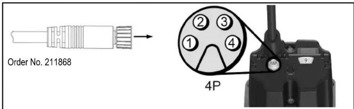
5.2.1 Assignment portal connector
All pins on the portal connector are protected against reverse polarity. At voltages above 30V , continuous operation with reversed polarity must be avoided as this can lead to failure of the interface.
| Pin No. Parameter | Colour of wire Order No. 211868 | |
| 1 | UNC | Brown |
| 2 | Us | White |
| 3 U | o Black | |
| 4 | GND | Blue |
5.3 Speed specification
With the setting wheel X (Fig. 2) you can adjust the speed continuously. The concrete speed values of individual stages can be found in the table on page 5 or on the speed sticker on the housing.
Until the motor characteristic is reached, the built-in electronics readjust to the set speed.
5.3.1 Speed setting in NC design
In "portal mode", the position of the setting wheel X (Fig. 2) for the speed setting is ignored. The speed can only be changed by the voltage at the pin "Us". If you wish to set the speed by means of the setting wheel X (Fig. 2), "portal mode" must first be deactivated by switching off the power supply at the pin "U NC" or by removing the control cable.
The correlation between speed and control voltage is illustrated in formulae (1) and (2).
$$ \begin{array}{l} U s = \frac {n - 4 0 0 0 \min ^ {- 1}}{2 1 0 0 \frac {\min ^ {- 1}}{V}} (1) \ n = U s * 2 1 0 0 \frac {\min ^ {- 1}}{V} + 4 0 0 0 \min ^ {- 1} (2) \ \end{array} $$
5.4 Overload protection

Danger
If you carry out any work on the working spindle after the overload protection has triggered, the mains plug must first be removed.
To protect the milling motor, the operating parameters current, speed and temperature are dynamically monitored and the power tool is switched off if necessary. Shortly before the overload protection is tripped, the illumination of the setting wheel X (Fig. 2) changes to a permanent red (RD).
To put the milling motor back into operation, you must open and close power switch 5 (Fig. 1). The milling motor goes into operation and the illumination of the setting wheel X (Fig. 2) changes to blue (BU).
5.4.1 Optical display of the remaining runtime
Triggering of the overload protection during operation leads to breakage of the milling tool, damage to the workpiece or even damage to the portal system. You can prevent this by paying attention to the visual output signals at the setting wheel X (Fig. 2).
As long as the milling motor is not overloaded in terms of performance, the setting wheel lights up permanently in blue (BU).
If the milling motor is overloaded, the calculated remaining runtime is displayed flashing in red (RD). On page 6 (Fig. 7) you can see the temporal arrangement of the pulses in overload mode. The correlation between the flashing behaviour and the associated remaining runtime is shown in the bottom table 4 on page 31.
If the remaining runtime is not sufficient for your application, reduce the load or feed rate to be able to switch back to continuous operation.
5.4.2 Display of the remaining runtime in the NC design
If the milling motor is in "portal mode", the remaining runtime can be queried via the interface in addition to the visual display.
The bottom table shows the correlation between the remaining runtime and the associated output variables.
Table 4: Correlation between the remaining runtime and the associated output variables
| Operating mode | Remaining runtime / s | Display remaining runtime \( U_0 / V \) | Setting wheel - illumination |
| Continuous operation | unlimited | 0 | Blue (BU), permanent |
| Overload mode (motor is running) | < 160 | 1.5 | 1 x red pulse (RD) |
| < 80 | 2.5 | ||
| < 40 3 2 x red pulse (RD) | |||
| < 20 4 | |||
| < 10 | 4.5 | 3 x red pulse (RD) | |
| < 5 | 5 | Red (RD), permanent | |
| Switch-off 0 5 | |||
6 Service and maintenance

Danger
Pull the power plug during all service work.
MAFELL machines are designed to be low in maintenance.
Replace the carbon brushes at the latest after 125 - 150 operating hours. The spare parts can be referenced in chapter 9.
The ball bearings used are greased for life. When the machine has been in operation for a longer period of time, we recommend to hand the machine in at an authorised MAFELL customer service shop for inspection.
Have your power tool serviced by a qualified repair person using only identical replacement parts. This will ensure that the safety of the power tool is maintained.
6.1 Storage
If the milling motor is out of service for a lengthy period of time, it should be thoroughly cleaned. Spray bright metal parts with a rust inhibitor. Close the portal connector with the supplied covering cap Z (Fig. 4).
7 Troubleshooting

Danger
Determining the causes for existing defects and eliminating these always requires increased attention and caution. Pull the mains plug beforehand!
Some of the most frequent defects and their causes are listed in the following chart. In case of other defects, please contact your dealer or the MAFELL customer service directly.
| Defect | Cause | Elimination |
| The milling motor cannot be switched on The setting wheel does not light up | There is no mains voltage | Check the power supply |
| The mains fuse is defective | Replace the mains fuse | |
| The milling motor cannot be switched on. The setting wheel lights up in blue (BU) | The carbon brushes are worn | Take the milling motor to the MAFELL customer service |
| The milling motor stops during operation. The setting wheel does not light up | Mains failure | Check the mains back-up fuses |
| The milling motor stops during operation. The setting wheel lights up in red (RD) | The overload protection was triggered | Switch off the power switch. Clear the working spindle before initial operation Switch on the power switch and continue operation with reduced load/feed rate |
| The speed cannot be adjusted at the setting wheel | The milling motor is in portal mode | Switch off the power supply of the interface Remove the external connection of the interface |
| The speed cannot be controlled via the interface | The power supply of the interface is missing / is inadequate | Switch on the power supply of the interface in accordance with the specification |
| The contacting to the portal connector is insufficient | Check the contacting | |
| The control cable is defective Rep | ace the control cable | |
| The assignment of the interface is incorrectly connected with the portal system | Connect the control cable according to chapter “Assignment portal connector” |
8 Optional accessories
- Collet OZ8 0 2 mm Order No. 093819
- Collet OZ8 03 mm Order No. 093812
- Collet OZ8 04 mm Order No. 093813
- Collet OZ8 05 mm Order No. 093820
- Collet OZ8 6 mm Order No. 093814
- Collet OZ8 0 8 mm Order No. 093815
- Collet OZ8 0 10 mm Order No. 093822
- Collet OZ8 01/8" (3.175 mm) Order No. 093810
- Collet OZ8 01/4" (6.35 mm) Order No. 093811
- Collet OZ8 03 mm + union nut Order No. 093816
- Collet OZ8 01/8" (3.175 mm) + union nut Order No. 093817
- Collet ER 16 Ø 3 mm Order No. 093753
- Collet ER 16 4 mm Order No. 093754
- Collet ER 16 6 mm Order No. 093755
- Collet ER 16ø8mm Order No.093756
- Collet ER 16 Ø 3.175 mm (1/8") Order No. 093757
- Collet ER 16 0 10 mm Order No. 093759
- Collet ER 16 6.35 mm (1/4") Order No. 093760
- Union nut OZ8 Order No. 093818
- Union nut ER 16 M Order No. 093758
-Adapter sleeve 3mm Order No.207944
-Adapter sleeve 1 / 8" (3.175 mm) Order No.207945
-Adapter sleeve 1 / 4" (6,35 mm) Order No.207947
-Adapter sleeve 4mm Order No.207949
-Adapter sleeve 6mm Order No.207946 - Collet adapter OZ8 incl. union nut OZ8 Order No. 208962
- Collect adapter ER 16 incl. union nut ER 16 Order No. 208109
- Control cable NC, 5 m black Order No. 211868
9 Exploded drawing and spare parts list
The corresponding information in respect of spare parts can be found on our homepage: www.mafell.com
Sommaire
9M0001, 9M0020, 9M0021, 9M0023
FM 1000 NC-ER
9M1401
FM 1000 NC-WS
9M1301
9M0001, 9M0020, 9M0021, 9M0023
FM 1000 NC-ER
9M1401
FM 1000 NC-WS
9M1301
9M0001, 9M0020, 9M0021, 9M0023
FM 1000 NC-ER
9M1401
FM 1000 NC-WS
9M1301
$$ P A = 3 d B (A) $$
Geluidsniveau
$$ \mathrm {L} _ {\mathrm {P A}} = 8 2 \mathrm {d B} (\mathrm {A}) $$
Onzekerheid K
$$ P A = 3 \mathrm {d B} (A) $$
9M0001, 9M0020, 9M0021, 9M0023
FM 1000 NC-ER
9M1401
FM 1000 NC-WS
9M1301
9M0001, 9M0020, 9M0021, 9M0023
FM 1000 NC-ER
9M1401
FM 1000 NC-WS
9M1301
$$ P A = 3 \mathrm {d B} (A) $$
Aänitehotaso
$$ \mathrm {L} _ {\mathrm {W A}} = 8 2 \mathrm {d B} (\mathrm {A}) $$
Epavarmuus K
$$ \mathrm {P A} = 3 \mathrm {d B} (\mathrm {A}) $$
9M0001, 9M0020, 9M0021, 9M0023
FM 1000 NC-ER
9M1401
FM 1000 NC-WS
9M1301
$$ P A = 3 \mathrm {d B} (A) $$
Ljudeffektnivá
$$ \mathrm {L} _ {\mathrm {P A}} = 8 2 \mathrm {d B (A)} $$
Osakerhet K
$$ \mathrm {P A} = 3 \mathrm {d B} (\mathrm {A}) $$
4 Forbereda/stalla in
4.1 Natsaslutning
9M0001, 9M0020, 9M0021, 9M0023
FM 1000 NC-ER
9M1401
FM 1000 NC-WS
9M1301
2.1 Producentinformationer
MAFELL AG, Beffendorfer Straße 4, D-78727 Oberndorf / Neckar, Telefon +49 (0)7423/812-0, fax +49
(0)7423/812-218, e-mail mafell@mafell.de
$$ P A = 3 \mathrm {d B} (A) $$
Lydeffektniveau
$$ \mathrm {L} _ {\mathrm {W A}} = 8 2 \mathrm {d B} (\mathrm {A}) $$
Usikkerhed K
$$ \mathrm {w} _ {\mathrm {A}} = 3 \mathrm {d B} (\mathrm {A}) $$
9M0001, 9M0020, 9M0021, 9M0023
FM 1000 NC-ER
9M1401
FM 1000 NC-WS
9M1301
2.1 CBeDeHnO npOn3BODHTeNe
MAFELL AG, Beffendorfer Straße 4, D-78727 Oberndorf / Neckar, Teilepoen +49 (0)7423/812-0, φaκc +49 (0)7423/812-218, Νλ. noγτa mafell@mafell.de
2.2 MapknipobKa MaunHbI
Bce daHHbI, Heo6xoDnMbIe Ia IneHTnФuKaIIMaHINbI, yKa3aHbI Ha 3aBOJcKo Ta6JIuYe.

Knacc 3auntbI II

CnMBOJ CE IJII NOITBepKJeHnA COOTBETCTBnO OCHOHBIM Tpe6oBaHnM 6e3oNaChocTn IN 3dpabooxpaHeHnI corlaacHO npInIOKeHnIO I K DnpeKTnBe o MaunHax

TolboKo dIa cTpaH EC
He BbIKnDbIbAaTe Φpe3epHbIe DbIraTeJIb B bItOBoMycOp!
Cornacno Ebponecko dnpekTbe 2002/96/EC o6 yctapeBwix 3neKtpuecknx n 3neKtpoHHbIX np6opax n aHaIOnuHbIM 3aKOHAM OTDeJIbHbIX CTpaH, IcNoJIb3OBaHHbIe fpe3epHbIe DBrIaTeJn DOJXHbI CObIpaTbcr OTrdJIbHO n IpeDaBaTbcra dna DaIbHeIwero IcNoJIb3OBaHHra 6e3 yUeP6a dnn OkpykaioSei Cpebl.

ypOBeHb 3BykoBOrO daBneHnA L PA74 dB (A)
norpewhoctbK 3D5(A)
ypoBHe 3ByKOBoMooHocTn LwA 82 d5 (A)
norpeuhoctbK WA3D5(A)
I3mepenHe yMa npOboDInocb 6e3 nHcTpymeHTa Ha xOIOCTOM XOy.
2.5 KomnneKT noctabkn
| EM 800 | EM 1000 | FM 1000 NC-ER | FM 1000 NC-WS | |
| Иnstрукция по заclпуатаци x x x x | ||||
| Односторонni Геуньий клоч SW 17 | x | x | - | - |
| Односторонni Геуньий клоч SW 25 | - | - | x | - |
| Цанговий патPOR OZ8 ø / мм | 6 | 8 | - | - |
| Цанговий патPOR ER 16 - - 8 - | ||||
| Кабел / m | 1 | 4 | 0,75 + 4 | 0,75 + 4 |
| Крышka Z | - - x x |
2.6 IcnoJb3OBAHHe no Ha3HaueHnO
- Φpe3epHbI DvBraTeNb IpeDHa3HaueH IЯ CTaCNoHapHOYCTaHOBKn B BeDyux CnCTeMax nopTaJa C 3axmHoi WeiKo 43 MM.
- Φpe3epHbI DnBraTeJIb C 6bIcTpbIM 3aXHMOM MOxHO 3aKpeNITb HENOCpeDCTBeHHO Ha CNCTeMe NOPTaJa C NOMOJIO WecTN BHTOB (pe3b6a M6) B COOTBETCTBNI CO CneUΦnKaunm CNCTeMbl NOPTaJa (pnc.5).
- Φe3epHbI DnBraTeIb He npEHa3HaueH dIa HnpepbIBHO npOMbiUHeHHO 3KcNpyaTuIN.
- Φpe3epHbI DBrAteIb paccMaTpnaBaTcKaK HEnoHa MaunHa.Φpe3epHbI DBrAteIb MoXeT 6bITb BBeHeB 3KcNlYatauTOJbKO B TOM Clyuae, ecn OnpedeJeHO, YTO CNCTema NOpTaJa, B KOTopyo DOJnxEh 6bITb yCTaHOJIeH φpe3epHbI DBrAteIb, COOTBetCTByET NOLOxEHnAM DeiCTByUoIero pyKOBODCTBa nO TexHNueCKOMy 06CnykuaHIO. TAKKe 06patnte BHMaHne Ha COOTBetCTByUoIue ycNoBra rapaHTm Φpe3epHOrO DBrAteIa NIOBOrO dONoHNtEhBOrO o6OpydoBaHnI.
2.7 OctaToUHbIe pMCKN

Onacho
B cIyae nCnoJb3ObaHn no Ha3haueHnIO HecMOTpHa co6IIOHeHne npaBnTexNk 6e3oNaChOCTn BCE Je octaOTc8 OCTaTOUHbE pNUCKN, Bbl3bIBaEMbIE Ha3HaueHnEM, KOtOpBle MOrY T npNBecTn K NocJeCTBnM dJa 3DopOBb.
-Поломka Врацаюцeroинстума.
-ПоломkaиИЗВлесенгИнHCTpymeHTOBИИчTeI INHCTpymeHTOB.
- KacaHne TokonpoBODaIcx DeTaJIe npn OTkpblTom Kopnyce n He BbITaHyToB BNlKe NITaHna.
- YxuDHeHne cnyxa npn dInTeBHO pa6oTe 6e3 cpeCTb 3aunTbI opraHOB cnyxa.
- Bыдение п徳савлгюшей угposу здоровью ИИВЗрьBOONACHОипIN (BCEX BIDOB) рпДПNTeNBHOn
ненрерьIBHон Экплугатуши 6e3 оTCoca. СблЮдайт паспорТ 6e3ОпАСНСТИ МATEРИА, поДжewsero
obpa6OTke.
3 YukazannnoTexnke6e3onacHocTN

Onacho
Bcerda co6nOaIte npBBeHbIe daIee yka3aHna I0 6e3oNaChocTn n npaBnIa texnKn 6e3oNaChocTn, DeIcTByUOJIne B cTpaHe, rIe npImeHЯTeCnIHa!
06üne yka3aHn:
- 3anpeuaeTc obaaatbca c 3toi MaunHoi DeTm n noDpoCTkam. NcknOueHne coCTaBnaIOT noDPOCTkn, paobTaIOUe IOd hAbIODeHem CneuaNtcta C cJIbIO obyuHnra.
- Hnkorda He pa6oTaIe 6e3 npedncaHbIX dIra COOTBeTCTByOuIe Oepaun 3aunTHbIX yCTpoiCTB CnCTemblnpTaI, B KOTOpOnIcNoJIb3yETcA ppe3epHbI DnurTaTeIb. He MeHJte B CnCTeme NpTaIa I ppe3epHom DBnurTaTeIe HnUero, YTO CB3aHO C TexHkoB 6e30NaCHOCTN.
-Повржденье Кабели Ил Вилки СседуET HeMeДпЕнHO 3aMeHHTb. 3aMeHa DoJxHa nPOn3BODITbcr ToIbko CpeuaJIncTamM MAFELL IIN aBTOpU3OBAHbIM cepBucHBIM ceHTpOM MAFELL BO n36eKaHne pNCKOB yRpo3blДЯ 6e3OpacHoCTn. - I36eraIte pe3Knx nepenibob Ka6e. Oco6eHNO npu TpaHcnpTIpOBke n XpaHeHn fpe3epHoro dBirataTeJ He HamaTbIBaIte Ka6eB BOKpyfpe3epHoro dBirataTeJ.
- IcnoIb3OBAHnE C BOoI INI TOKOpBOJIMM XJIDKOCTAMN 3aIpeJeHO.
- Φpe3epHbI DnBraTeIb He DoJIxKeH IcNoJIb3OBAtbcr CpyHbIM ynpaBHeHneM.
- He noDBepraIte fpe3epHbI dBIrataIb BO3eIcTBIO DoXJa IIN BlaRn. IOnaHaHne BoIbI Bo fpe3epHbI dBIrataIb IOBbIaEaT ONaCHOCTb IopaxeHn 3JIeKTPuYeCKM TOKOM.
He pa3pewaeTcNcNoIb3OBaTb:
- NobpeKdEHHbIe IeΦopMnPoBaHHbIe IHcTpymeHTbl.
- TynbIe INHCTpyMeHTbl N3-3a CnIIWkOM 6oJIbWoHarpy3Kn DBrVaTeJIA.
- INCTpymEnTbI, KOtOpBIE He NOxOaT dJa YactOTbI BpaUeHn Ope3epHO DBrAteJI Ha XONOCTOM XOyD.
Yka3aHnno npimHeHHo cpeCTB NCHOH 3auNTbI:
-BoBpempa60tI Bcerda nCnoJb3OBA Tb 3aunTy opraHOB cnlyxa.
-BoBpeMaPbI Bcerda HcNoJIb3OBA Tb npOTnBOJbIeBOI pecnnpaTOp.
- Ppi pa6oTe Hocnte 3aunTHbIe OcKn.
Yka3aHnno 3Kcnnyatau:
- He npikacaiTecb pykami K onachomy yuactky uHCTpymEnta.
- PpObePraTe 3aROToBky Ha HaNuHne HnOpOndbIX TeI.
- KoHTpOJIpyIe YactOTy BpaIeHn. Ipr Bo3HnKHOBeHn HeKOHTpOJIpyEmo r yBeJIuYeHn YactOTbI BpaIeHn, cKaIcYacTObI BpaIeHn, Heo6XoIMo HemeJIoEHn OTKJIIOHTb 3JIeKTPOnHCTpyMeHr OT NCTOHHa PNTAHn.
Yka3aHnno TExHHueckomy 06cIyXnBaHnIO n TeKyuemeMy pemOnTy:
- PerylpaHaa YnCTKa fpe3epHoro DnBraTeJRAJBJeTc BaxKbIM fakTopoMa HAdexKHOCTN
- Pa3pe7aetc nCNoIb3OBAHne TOnbKO opnHaJIbHbIX 3anaChbIX qacteN npHaJNeJxHocTei CpnpMb1 MAFELL. B npOTNBOM cIyueae npTeH3nn, OTHOcAUIeCRApaHTn N OTBeTCTBENHOCTn I3rTOBNTeJI, He npINHMaOTc.
4 Ochauene / NaCTpoiKa
4.1 PoiKJIIOUeHne K cTeN
Ipeed BBOOM B 3KcnpnyatauHcneHTE 3a TEM,HTObI HnprjXeHne B CETN COOTBETCTBOBaIPO pa6oemy HnprjXeHIO,yKa3aHHOMy Ha 3aOBdCKoT a6nUKe fpe3epHOro dBiratela.
4.2 BbI6Op nHcTpymeHTa
IcnoJIb3yIte TOnIbKO yka3aHHbIe B rIabe «CneuHaJIbHbIe npHaJNeJxHocTn» ZaHROBble NaIpoHbI/pePexOdHbIE Btyn. BbI6op IHCTpyMeHTa ocUeCTBnErcTc B 3aBNCMOCn OT MaTePnaIaOB, NOJIeKaIux OpbAobTkce, C yYeToM MoIHOCTN NOdaIOUnx PpIBoDOb. IprMaKcMaJIbHOM DnAmEtpe INCTpyMeHtA n rIy6nHe OpbAobTkIn yUHTbIbAIte MOUHcTb φpe3epHOrO DBIrataJIe.
4.3 ondeBaIte

Onacho
При поведени лобьх paBOT NO ТХнчecKOMу obCnyЖИВaHIb BblIMaTb BnIky coeINHITeNBHO shhya.

NcnoJIb3yIte 3aUHTHbIe nepuATKn npn CMeHe NHCTpyMeHTa. NcNoJIb3yeMbI INHCTpyMeHT MOKeT CNbHO HArpeBaTbC8BO BPeMg DInTeNbHOrO NcNoJIb3OBaHn, n/In pexKyUne KpOMKn INHCTpyMeHTa OCTpbIe.
4.3.1 3axim nHctpymeHTa c nomoubIu zHaHroBOrO naTpoHa
UHHdIb 1 (pnc. 1) φpe3epHO-шнфOBaHbHorO DBuRaTeJI OCHaSeH npeuNHOHBIM cAHROBbIM NaTPOHOM 2 (pnc. 1)ДЯЗЖIM aHCTpyMeHTOB.БLOKINPOBka UHHdJIa OCyUeCTBJIeTcR C NOMOuH KHOKN bIOKINPOBKn 4иОBJeHaET 3aTAYBaHneи Ocna6JIeHne HAKnHOr RaKn 3 (pnc. 1).
CmeHa HnctpyMeHtA OcyuEcTBJraTcB CneDyUoem NoprIke:
- Yto6bI CHaTb INHcTpymeHT, 1 (pnc. 1) 6nOKpyoT HaxaTneM KhoNk 6nOKpOBKn 4 (pnc. 1).
- HakuHyu raiky 3 ocna6nHOT oNHOCTOpOHnM raeHbIM KIOUOM SW 17 nn 3aKmHbIM KIOUOM ER 16 M.
- INHCTpymEnT BbITaRnBaIOT BnepeId.
- HoBbI INHCTpyMeHT BCTaBnIAOT Do yNopa B 3axIM INHCTpyMeHTa.
- Поверп Te поа К ИНСТуMeNTa.
-ПиЗakpenпенИнстчмЕТаБNotKpyeTcшпнДeЛь1(pnc.1). - HakuHyu rauky 3aTaRnBAIoT OndocToPOHHm raeHbIM KIOUcOM SW 17 nnn 3axmmhblm KIOUcOM ER 16 M.
4.3.2 BbIcTpoe KpenJIeHne HnCtpyMeHTa

Bknioautee ppe3epnbl DBnraTeIb TOnbKO torda, kOrda pbUar 6 (pnc. 3) He HaxoINTcB NIOLOXeHN CMeHb INHCTpyMeHTa.
IcnoIb3yIte pbIar 6 (pnc. 3) TOnbKO npn OTKJIIOUeHHOM fpe3epHom DBuratene.
7 (pnc. 3) 6bictporo kpeJIeHnIHcTpymeHTa OCHaueH npeU3HOHHbIM 3aXMMOM dIy XBOCTOBNk AHcTpymeHTa 08 MM.
CmeHa nHcTpymeHa ocyueCTBnIeTcB cJeDuOeM nopAKe:
- YTo6bI CHrTb INHcTpymeHT, nepemecnte pbiur 6 (pnc. 3) Bnpeid do ynopa.
- INHCTpymEnT BbITaRnBaIOT Bnepeid.
- HoBbI INHCTpyMeHT BCTaBJIOT Do yNopa B 3aJIM INHCTpyMeHTa.
-Поберп Te nocaДу ИНСТPyMeHTa. - Yto6bI 3aKpeHnTb INcTpymeHT, NpeMeecntTe pbUar Ha3aD B INCXoHoe NOLOKeHne.
4.4 ZaHroBbI naTpoH

Onacho
Hakundnyo raiky 3 (pnc.1) ha shinndele 1 (pnc.1) OTBnHnBaIte octopoxho, uTo6bl 3aunntb pe3b6y, n HNKOrda He 3atraNBaIte ee, ecIn He yctaHOHNCTpyMeHT. ZaHROBbI NaTPOH 2 (pnc.1) moKet 6bITb cINsKOM cnIbHo 3axaT, n, TAKIM o6pa30M, nobpejxden.
4.4.1 IHHOpMaunrO6 nCnoJIb3OBAHn ZaHROBbIX naTPOHOB:
- CцанroBbIM natoHOM OZ8 (DIN 6388 / ISO 10897) n ER16 (DIN 6499 / DIN ISO 15488) nCnoJb3yIte Φpe3bl npaBnBHO BELNCHbl
- Bcerda chayana BCTabnIte cahroBbI natoH b HauNHyraKy, a 3aTe MCTabJrTe fpe3y
- B cnyuae 3aknHbAHna ocna6bte cahroBbI natpoH cnerka yapnb ero c3aN KBaPaTHbIM bpycom nn pe3nHObblM MOJOTKOM (He MeTaNJIneCKm INHCTpyMeHTOM!)
- Cma3bIbAaTe ZaHROBble NaTPOHbI neped nepBOn 3KcNpyaTuuei N PocJe DInTeJbHOrO IcNoJIb3OBaHnE He6oJIbShM KOnUYeCTBOM Macna, INHaue OHN MOrY T 3aCtPraTb
- 3начительно Лушев Точно Врашени Таже мохно досточь, Истовская Тбердую смаши (Hapimep, Molykote P-40) ини слегка сma3bivая заимrobbie naTpoны
4.4.2 PekomeHdyembIMOMeHT3aTAAKKN(yuHTbIbAte BCIO CNTEmy)
Moment 3aT8KKn HauKndHou raKn / ZaHROBOro naTpoHa = 10-11 Hm
Momet 3aTJKK 3aJIMHOJ ueKn 43 MM = 7 H
EbpokpenJeHne V He doJHKHO 6bITb MeHbIe pa3Mepa h (pnc.8).Pa3Mep h coCTabJIaER 20 MM.
3aXMMTe 6pe3epHbI DnBraTeIb KaK MoXHO CnIbHee IIO BCEmy DnaMeTpY eBpokpenHeHnA «V1» (pnc.8). 3aTaNtB CTJxHOB BnHT «W» c MaKc. ycInnem 7 Hm. (Pnc.9)
5.1 BbO D B 3KcNpyaTaunIO
9M0001, 9M0020, 9M0021, 9M0023
FM 1000 NC-ER
9M1401
FM 1000 NC-WS
9M1301
2.1 Dane dot.producenta
MAFELL AG, Beffendorfer Straße 4, D-78727 Oberndorf / Neckar, Telefon +49 (0)7423/812-0, Faks +49
(0)7423/812-218, e-mail mafell@mafell.de
9M0001, 9M0020, 9M0021, 9M0023
FM 1000 NC-ER
9M1401
FM 1000 NC-WS
9M1301
2.1 Udaje k vyrobci
$$ P A = 3 \mathrm {d B} (A) $$
9M0001, 9M0020, 9M0021, 9M0023
FM 1000 NC-ER
9M1401
FM 1000 NC-WS
9M1301
$$ P A = 3 \mathrm {d B} (A) $$
Raven zvočne moči
$$ \mathrm {L} _ {\mathrm {W A}} = 8 2 \mathrm {d B (A)} $$
Negotovost K
$$ w A = 3 d B (A) $$
9M0001, 9M0020, 9M0021, 9M0023
FM 1000 NC-ER
9M1401
FM 1000 NC-WS
9M1301
2.1 Udaje o vyrobcovi
MAFELL AG, Beffendorfer Straße 4, D-78727 Oberndorf / Neckar, Telefon +49 (0)7423/812-0, Fax +49 (0)7423/812-218, Email mafell@mafell.de