LO 55 - Milling machine Mafell - Free user manual and instructions
Find the device manual for free LO 55 Mafell in PDF.


| Product type | Router |
| Brand | Mafell |
| Model | LO 55 |
| Category | Router |
| Service voltage | 230 V~ |
| Mains frequency | 50 Hz |
| Power consumption | 1100 W |
| Idle speed (normal mode) | 10,000 – 24,000 min⁻¹ |
| Idle speed (reduced mode) | 10,000 – 16,500 min⁻¹ |
| Cooling speed | 8,000 min⁻¹ |
| Milling depth adjustment | 0 – 55 mm (with 3-position turret stop and precision adjustment) |
| Tool fixation | Collet for shanks Ø 6 mm or 8 mm |
| Suction hose diameter | 26 mm |
| Weight (without mains cable) | 3.1 kg |
| Standard equipment | Parallel guide, precision adjustment, chip deflector, copy rings Ø 20/30/40 mm, suction adapter, adapter for F-rail, transport case, instruction manual, safety booklet |
| Intended use | Milling of solid wood, wood-based panels, plastics, Alucobond, and mineral materials with appropriate extraction |
| Safety devices | Wide base, handles, start-up lock, motor protection (automatic shutdown on overheating), LED status indicator |
| Sound pressure level (LPA) | 97 dB(A) (uncertainty KPA = 3 dB) |
| Sound power level (LWA) | 89 dB(A) (uncertainty KWA = 3 dB) |
| Hand-arm vibration | 2.9 m/s² (uncertainty 1.5 m/s²) |
| Maintenance and care | Regular cleaning of the collet, replacement of O-ring, clean and dry storage. Use only MAFELL spare parts. |
Frequently Asked Questions - LO 55 Mafell
User questions about LO 55 Mafell
0 question about this device. Answer the ones you know or ask your own.
Ask a new question about this device
Download the instructions for your Milling machine in PDF format for free! Find your manual LO 55 - Mafell and take your electronic device back in hand. On this page are published all the documents necessary for the use of your device. LO 55 by Mafell.
USER MANUAL LO 55 Mafell
natural_image
3D rendering of a black electric shaver with lever and base mount (no text or symbols visible)WARNUNG
Please read all safety instructions and directions. Failure to comply with the safety instructions and directions can cause electric shock, fire and/or serious injuries. Please retain all safety instructions and directions for future reference.
AVERTISSEMENT
natural_image
3D model of a mechanical device with a directional arrow and dimension label (20), no readable text or symbols beyond the number 3.MAF02343/a
natural_image
Mechanical assembly diagram showing a drill bit with a tool inserted, no visible text or symbolsMAF02344/a
natural_image
3D rendering of a power tool with labeled part 18 (no text or symbols on the device itself)MAF02345/a
MAF02346/a
MAF02347/a
natural_image
3D rendering of a mechanical power tool with a lever and base mount (no text or symbols visible)MAF02348/a
MAF02349/a
GB - EC Declaration of Conformity
We herewith confirm that the machine LO 55 complies with the EU directives quoted. The standards listed were used for design and construction. Empowered person for the configuration of the technical documents: Mafell AG
| 1 | Signs and symbols | 23 |
| 2 | Product information | 23 |
| 2.1 | Manufacturer's data | 23 |
| 2.2 | Machine identification | 23 |
| 2.3 | Technical data | 24 |
| 2.4 | Emissions | 24 |
| 2.5 | Shafts of the milling cutters | 24 |
| 2.6 | Scope of supply | 25 |
| 2.7 | Safety devices | 25 |
| 2.8 | Use according to intended purpose | 25 |
| 2.9 | Residual risks | 25 |
| 3 | Safety instructions | 26 |
| 4 | Layout | 27 |
| 4.1 | Depicted components | 27 |
| 5 | Setting / adjustment | 27 |
| 5.1 | Mains connection | 27 |
| 5.2 | Chip and dust extraction | 27 |
| 5.3 | Clamping of milling cutters | 28 |
| 6 | Operation | 29 |
| 6.1 | Initial operation | 29 |
| 6.2 | Motor protection | 29 |
| 6.3 | Speed adjustment | 29 |
| 6.4 | Milling depth adjustment | 30 |
| 6.5 | Work instructions | 31 |
| 7 | Service and maintenance | 32 |
| 7.1 | Cleaning the collet | 32 |
| 7.2 | Replacing the O-ring in the clamping sleeve | 32 |
| 7.3 | Storage | 32 |
| 8 | Visual signal indication of operating condition | 33 |
| 9 | Troubleshooting | 33 |
| 10 | Optional accessories | 35 |
| 11 | Exploded drawing and spare parts list | 35 |
1 Signs and symbols

This symbol is found in all places where you will find information for your safety.
Non-compliance with these instructions may result in very serious injuries.
This symbol indicates a potentially hazardous situation.
If this situation is not avoided, the product or objects in its vicinity may get damaged.

This symbol indicates tips for the user and other useful information.
2 Product information
for machines with product no. 91A901, 91A920, 91A921
2.1 Manufacturer's data
MAFELL AG, Beffendorfer Straße 4, D-78727 Oberndorf / Neckar, Phone +49 (0)7423/812-0, Fax +49 (0)7423/812-218, e-mail: mafell@mafell.de
2.2 Machine identification
All details required for machine identification are available on the attached rating plate.

Protection class II

CE symbol to document compliance with the basic safety and health requirements according to Appendix I of the Machinery Directive.
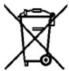
For EU countries only
Do not dispose of electric tools together with household waste material! In accordance with the European directive 2002/96/EC on waste electrical and electronic equipment and transposition into national law, obsolete electrical tools must be collected separately and recycled in an environmentally-compatible manner.

To reduce the risk of injury, please read the operating instructions.
2.3 Technical data
| Operating voltage | 230 V~ |
| Mains frequency | 50 Hz |
| Input power continuous operation 1100 W | |
| Idling speed normal operation | 10000 - 24000 rpm |
| Idling speed throttled operation | 10000 - 16500 rpm |
| Speed cooling run 8000 rpm | |
| Milling depth adjustment with fine adjustment | 0 - 55 mm |
| Revolving depth stop | 3-stage |
| Tool fastening with collets | 6 – 8 mm |
| Hose connector diameter 26 mm | |
| Weight without mains cable | 3.1 kg |
2.4 Emissions
The declared noise emission values have been measured in accordance with DIN EN 62841-1 and may be used for comparing the tool with another and also in a preliminary assessment of exposure.

Danger
The noise emissions during actual use of the power tool can differ from the declared values depending on the ways in which the tool is used especially what kind of workpiece is processed.
Always wear hearing protection, even when the power tool is running idle in addition to the trigger time!
2.4.1 Noise emission specifications
Noise emission values determined according to EN 62841-1 and EN 62841-2-17:
| Sound pressure level L | _PA = 97 dB (A) |
| Uncertainty K | _PA = 3 dB (A) |
| Sound power level | L_PA = 89 dB (A) |
| Uncertainty K | _PA = 3 dB (A) |
The noise level measurement was carried out with a new straight-edged milling cutter ( 12 mm).
2.4.2 Vibration specifications
The typical hand-arm vibration is 2.9 m/s ^4 .
The measuring inaccuracy is 1.5 m/s ^2 .
2.5 Shafts of the milling cutters
The shafts of the milling cutters must meet the safety requirements to EN 847-2. The shaft diameter must be of h8 quality:
- Shaft diameter 8mm: ∅ 7,978 - ∅ 8
- Shaft diameter 6mm: ∅ 5,982 - ∅ 6
- Shaft diameter 1 / 4 ": ø 6,328 - ø 6,35
2.6 Scope of supply
Router LO 55 complete with:
1 parallel guide fence
1 fine adjustment
1 chip deflector
1 template guide ∅ 20 mm, ∅ 30 mm, ∅ 40 mm
1 template guide adapter
1 extraction adapter
1 extraction adapter for guide rail
1 adapter sleeve 14 " (only for item No. 91A921)
1 carrying case
1 operating manual
1 folder "Safety instructions"
2.7 Safety devices

Danger
These devices are required for the machine's safe operation and may not be removed or rendered inoperative.
Before operating the machine, check the safety devices for function and possible damage. Do not use the machine with missing or ineffective safety devices.
The machine is equipped with the following safety devices:
- large base plate
- Handles
- Index mechanisms
- Extraction adapter
2.8 Use according to intended purpose
The MAFELL router LO 55 is exclusively intended for milling of solid wood and panel materials such as chip board, coreboard, synthetic board, MDF board and Alucobond board using HSS or TCT milling cutters. Mineral materials (plasterboard or other dry construction materials) can also be milled. During milling, pay attention to best possible extraction and cleaning of the machine.
Any other use than described above is not permissible. The manufacturer cannot be held liable for any damage arising from such other use.
So as to use the machine as intended, comply with the operating, maintenance and repair instructions specified by Mafell.
2.9 Residual risks

Danger
Even if used in accordance with its intended purpose and despite conforming with the safety instructions, residual risks caused by the intended use that can lead to health consequences will always remain.
- Touching the running milling cutter or the clamping sleeve.
- Breakage of the milling cutter and risk of the milling cutter or pieces of the milling cutter being hurled away.
- Backlash of the machine or the workpiece.
- Backlash of the machine if the milling cutter gets stuck in the workpiece.
- Hearing can be impaired when working for long periods without ear protectors.
- Emission of harmful wood dusts during longer operation without extraction.
3 Safety instructions

Danger
Always observe the following safety instructions and the safety regulations applicable in the respective country of use!
Also read the safety instructions in the enclosed booklet "Safety instructions".
General instructions:
- Children and adolescents must not operate this machine. This rule does not apply to young persons receiving training and being supervised by an expert.
- Never work without the protection devices prescribed for the respective operating sequence and do not make any changes to the machine that could impair safety.
- When operating the machine outdoors, use of an earth-leakage circuit-breaker is recommended.
- Damaged cables or plugs must be immediately replaced. Replacement may only be carried out by Mafell or an authorised MAFELL service workshop in order to avoid safety hazards.
- Avoid sharp bends in the cable. Especially when transporting and storing the machine, do not wind the cable around the machine.
- Only use milling cutters approved for manual feed.
- Only begin milling the workpiece when the milling cutter has achieved its full speed.
- Only put down the machine after switching off once the milling tool has come to a standstill.
Do not use:
- Cracked and misshapen milling cutters.
- Blunt milling cutters as they impose an excessive load on the motor.
- Milling cutters that are not suitable for the milling idling speed.
Instructions on the use of personal protective equipment:
- The noise pressure level at the ear generally exceeds 85 dB(A). Therefore wear ear protectors during work.
- Wear protective goggles during work.
- Wear a dust protection mask to prevent health damage.
- Danger of cuts when changing the milling cutter. Therefore, wear protective gloves when changing the milling cutter.
Instructions on operation:
- Never reach into the working range of the milling cutter or underneath the base plate while the machine is running (danger of injury)!
- Firmly hold onto the machine with both hands at the handles provided already before switching it on.
- Provide a free and non-slip location with adequate lighting.
- The power plug must be pulled before replacing tools, making adjustments and repairing malfunctions (this also includes removing jammed chips).
- Examine the workpiece for foreign objects. Do not mill into metal parts, e.g. nails (danger of backlash).
- Before starting up, check the tight seat of the milling cutter and its correct running.
- Only use milling cutters approved for manual feed.
- Only use sharp and undamaged milling cutters. You will achieve improved surfaces and reduce the danger of backlash.
- Do not work on workpieces that are too small or too large for the capability of the machine.
- Only hold the power tool by the isolated handles, as the milling cutter could encounter and cut into its own connecting cable. The milling cutter contacting a "live" wire may render exposed metal parts of the tool "live" and could cause the operator to suffer an electric shock.
- Use clamps or another practical way to secure and support the workpiece to a stable support. Holding the workpiece only with your hand or against your body leaves it unstable and may lead to loss of control.
-
Only begin milling the workpiece when the milling cutter has achieved its full speed.
-
Always lead the connecting cable away from the machine to the rear while milling.
- An even feed during milling increases the life time of milling cutter and machine and achieves a clean milling pattern. Always mill in counter direction when machining edges.
- Only put down the machine after switching off once the milling cutter has come to a standstill or unscrew the clamping for the automatic reverse stroke on the machine. The machine is locked by releasing the column clamping lever 18 (Fig. 2).
- Milling cutters must be replaced in good time, as blunt milling cutters do not only increase the danger of backlash, but also place an unnecessary strain on the motor. The milling cutters must be clamped in accordance with chapter 5.3.
- The wood dust arising during milling impairs the necessary view and is partly injurious to health. If the machine is used for longer periods, it must therefore be connected to a chip extractor, e.g. a portable small extractor, if the work is not carried out outdoors or in a sufficiently ventilated room. The air velocity must be at least 20 m/s.
Stationary use:
- Any stationary use, even on work tables, is prohibited.
Instructions on service and maintenance:
- Regularly cleaning the machine, especially the adjusting devices and guides, constitutes an important safety factor.
- Only original MAFELL spare parts and accessories may be used. Otherwise the manufacturer will not accept any warranty claims and cannot be held liable.
4 Layout
4.1 Depicted components (see Fig. 1 and 2)
(1) Depth stop
(2) Handle depth stop
(3) Scale for the depth stop
(4) Optical fibre speed adjustment
(5) Speed push button
(6) Speed reduction button
(7) Power-on lock
(8) Handle
(9) Connecting cable
(10) Switch trigger
(11) Hose connector
(12) Wing screw for support foot
(13) Wing screw to fasten parallel guide fence, extraction adapter, chip deflector and template guides
(14) Base plate
(15) Revolving depth stop with grub screws
(16) Fine adjustment depth stop
(17) Cam lever
(18) Column clamping lever
(19) Handle
5 Setting / adjustment
5.1 Mains connection
Prior to commissioning make sure that the mains voltage complies with the operating voltage stated on the machine's rating plate.
5.2 Chip and dust extraction
Chips arising during milling as well as hazardous dusts arising from certain materials can be extracted by means of a commercial vacuum cleaner or with an external dust extractor.
To do so, attach the hose end of the vacuum cleaner to the hose connector 11 (see Fig. 2) of the base plate.
For improved extraction, an additional extraction adapter can be used (included in the scope of supply).
When working with a guide rail, an extraction adapter with height compensation (included in the scope of supply) is used.
When machining edges, a chip deflector which guides any arising chips away from the operator and improves extraction can be additionally mounted. The chip deflector is included in the scope of supply.
5.3 Clamping of milling cutters
The machine is as a standard equipped with a ∅ 8 mm precision collet. It is possible to fasten milling cutters with corresponding shank diameter in this collet (see chapter 2.5).

Danger
It is imperative to pull the mains plug before replacing the milling cutter. Place the machine on its head or put it down on its side. Do not set the machine down on the side with the hose connector! This can result in damage to the workpiece.
Wear protective gloves when changing the milling cutter. There is a danger of cuts!
Clamping
- Set the machine to the topmost position by actuating the column clamping lever 18 (Fig. 2).
- Open the tool clamping lever 20 (Fig. 3) completely downwards.
- Place the machine on its head or put it down on its side.
- Push the clean cylindrical shank of the milling cutter as far as possible into the open collet, but at least up to the marking for the minimum clamping depth, plus an additional 2 mm. If there is no marking for the minimum clamping depth, push the cylindrical cutter shank as far as possible - but at least three third of the shank - into the open collet.
- Push the tool clamping lever 20 upwards to close it.
- Place the machine onto the base plate 14 (Fig. 1).
Unclamping
- Set the machine to the topmost position.
- Open the tool clamping lever 20 (Fig. 3) completely downwards.
- Place the machine on its head or put it down on its side.
- Remove the milling cutter from the collet.
- Push the tool clamping lever 20 upwards to close it.
- Place the machine onto the base plate 14 (Fig. 1).

A special application is at hand when working with guide sleeves/template guides and for example a comb jointer. If the inner diameter of the guide sleeve/template guide is smaller than the outer diameter of the milling cutter, it is not possible to drive the machine into the topmost position. It is therefore necessary to open the tool clamp as follows:
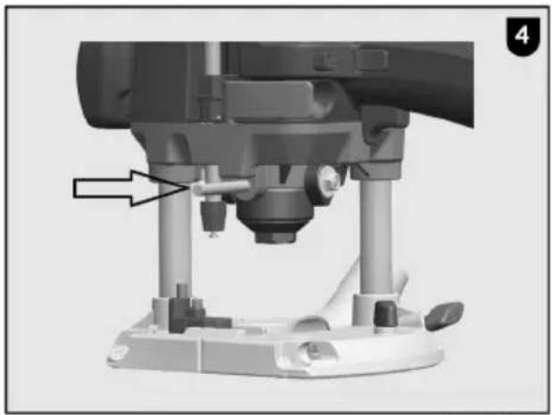
- Use a ∅ 6 mm round bar (see Fig. 4) and push it through the bore in the fan housing.
- Turn the tool clamp until the round bar engages and blocks the tool clamp.
- Use a ring wrench or open end wrench AF19 to open the clamping sleeve by approx. 4 turns (clockwise rotation, left-hand thread).
- You can now remove the milling cutter from the collet or insert it into the collet.
- Re-tighten the clamping sleeve (anti-clockwise rotation, left-hand thread) and pull off the round bar.
6 Operation
6.1 Initial operation
Personnel entrusted to work with the machine must be made aware of the operating instructions, calling particular attention to the chapter "Safety instructions".
6.1.1 Switching on and off (see Fig. 1)

Danger
Only switch on the machine if the milling cutter has no contact with the workpiece and the tool clamping lever has engaged.
If the machine is switched on when it is in contact with the workpiece, the LED display lights up red (steady light). The machine switches off automatically. Release the switch trigger, remove the machine from the workpiece and press the switch trigger again.
If the mains plug is plugged in, the working range of the machine is illuminated as soon as it is moved.
When the machine is switched on, the LED display indicates the last speed set. The LED display lights up blue.
If the LED display lights up red, there is an error (see chapter 8).
Short operation
- Switching on: Press the switch trigger 10 (Fig. 1).
• Switching off: Release the switch trigger.
Continuous operation
- Switching on: Press the switch trigger 10 (Fig. 1) and the switch-on lock 7 in succession. The motor runs without pressure on the switch.
- Switching off: Press switch trigger 10 until the locking button disengages, then release the switch trigger.

If within a time period (brake cycle) of 45 seconds, braking takes place more than four times, subsequent braking is suspended until the cycle time has expired.
6.2 Motor protection
Extreme and continuous overloading of the machine can lead to a motor failure. Before reaching a critical motor temperature, the motor is automatically switched off by the electronic temperature monitoring. When it is switched on again, the machine goes into cooling mode. The LED display flashes red. The bar value indicates the remaining cooling mode run time before the machine switches off automatically. When the machine has switched off, the LED display lights up red.
The machine is switched off due to overtemperature if the permissible motor temperature is exceeded while processing a workpiece. The LED display lights up red. When it is switched on again, the machine goes into cooling mode.
As an alternative, you can allow the machine to cool while it is switched off.
6.3 Speed adjustment
The router is equipped with an electronic speed control (see Fig. 1).
Speed normal operation
The milling cutter speed can be adjusted in 6 levels between 10000 and 24000 rpm via the speed button 5 (Fig. 1) below the LED display. When the machine is switched on with a soft start, the speed increases to the set final speed. The electronic levels are depicted in the following figure.
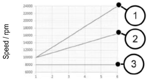
line
| Speed / rpm | Series 1 | Series 2 | Series 3 | | ----------- | -------- | -------- | -------- | | 1 | 10000 | 10000 | 8000 | | 6 | 24000 | 17000 | 8000 |Speed setting
(1) Normal operation
(2) Throttled operation
(3) Cooling run
Speed throttled operation
When processing end-grained wood surfaces, the speed can be lowered by 30%. To do so, press the speed reduction button 6 (Fig. 1). The LED display then flashes blue. The speed reduction is reset by pressing the speed reduction button again; the machine runs in normal operation again.
After a disconnection from the mains, the speed reduction is reset; the machine runs in normal operation again. The LED display lights up blue. When the machine is switched on, the LED display indicates the last speed set.
Which electronic level must be set for which milling cutter and material can be gathered from the following table.
| Material (Recommended cutting) | Milling cutter ∅ 3 – 14 mm | Milling cutter ∅ 15 – 25 mm | Milling cutter ∅ 26 – 35 mm |
| Hardwood (TCT / HSS) | 6 - 4 | 5 - 3 | 3 - 1 |
| Softwood (HSS / TCT) | 6 - 5 | 6 - 3 | 4 - 1 |
| Coated chip board (TCT) | 6 - 5 | 6 - 3 | 4 - 2 |
| Plastic (TCT) |

Danger
Do not work with the LO 55 if the electronic system is defective, as this may lead to excessive speeds. A faulty electronic system can be recognised by the lacking soft start, by a heightened idling noise or if no speed control is possible.
Speed cooling mode
If the machine is in cooling mode, the speed is automatically reduced to 8000 rpm.
Irrespective of the previously set speed, the spindle speed remains constantly at 8000 rpm.
The machine switches off when cooling mode is complete. When the machine is switched on again, it continues to run in normal operation.
6.4 Milling depth adjustment
6.4.1 Column clamping
The machine is equipped with a permanent column clamping.
By actuating the column clamping lever 18 (Fig. 2), the clamping is released and you can adjust the machine height.
Releasing the column clamping lever reactivates the clamping.
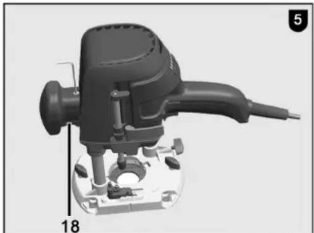
The column clamping can also be deactivated, for instance to drill rows of holes without having to constantly actuate the column clamping lever 18 (see Fig. 5). To do so, keep the column clamping lever 18 depressed. Insert an Allen wrench (2.5 mm) into the hexagon and turn 90° in clockwise direction.
Releasing is done in reverse order.
6.4.2 Revolving depth stop
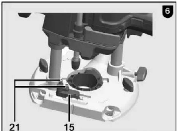
The revolving depth stop 15 (Fig. 6) can be used to set three different milling depths. In addition, a fine adjustment of the highest and medium milling depth can be made via two grub screws 21.
To prevent a misadjustment of the milling depth in case of an accidental actuation of the column clamping lever 18 (Fig. 1), the depth stop can be hooked into the revolving depth stop:
- First move the revolving depth stop 15 all the way to the left.
- Then turn the revolving depth stop 15 in anticlockwise direction.
- Now hook in the bar of the depth stop 1 (Fig. 1) by turning the revolving depth stop 15 in clockwise direction.
6.4.3 Adjustment of milling depth according to scale
The milling depth is set via the scale 3 (Fig. 1) for the depth stop.
- Clamp the milling cutter and place the machine onto the workpiece.
- Actuate the column clamping lever 18 (Fig. 2) and keep it depressed.
- Move the machine downwards until the milling cutter touches the workpiece surface. Now release the column clamping lever 18.
-
Open the cam lever 17 (Fig. 1).
-
Adjust depth stop 1 up to the stop screw on the revolving depth stop 15.
- Set the slidable scale needle on the depth stop 1 to the zero point of scale 3.
- Set the depth stop 1 to the desired milling depth and clamp it with the cam lever 17.
- Actuate the column clamping lever 18 (Fig. 2) to actuate a reverse stroke.
6.4.4 Fine adjustment of milling depth
If a delicate correction of the milling depth should become necessary, this is done by turning the fine adjustment 16 (Fig. 1). One turn of the adjusting nut causes a milling depth adjustment of 1 mm. The entire travel of the fine adjustment is approx. 10 mm.
6.5 Work instructions

Hold onto the machine with both hands during operation.
6.5.1 Plunge milling
A reduction plate reducing the tool opening to ∅ 32 mm is mounted on the underside of the base plate 14 (Fig. 1). The reduction plate facilitates machining in angular wooden areas and reduces the risk of slipping.
If necessary, the reduction plate can be removed to the top.
During milling ensure that the workpiece is secured and the router is resting evenly against the workpiece with the base plate 14 and / or the limit stops on an as large as possible surface.
Mill large depths progressively.
Once you have set the milling cutter speed, firmly hold onto the machine with both hands and switch on the machine. Actuate the column clamping lever 18 (Fig. 2) and plunge the milling cutter into the material up to the stop with an even feed. Releasing the column clamping lever 18 locks the machine. Only mill in counter direction.
6.5.2 Milling with parallel guide fence
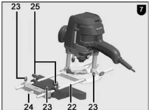
The parallel guide fence is used to accurately guide the machine along a straight workpiece edge (see Fig. 7). The parallel guide fence is included in the scope of supply.
Conversion:
- Push the guide rods 22 into the two openings of the base plate.
- Roughly set the parallel guide fence to the desired distance to the milling cutter and tighten the wing screws 23.
- Use knurled screw 24 to accurately set the distance to the milling cutter and then tighten the wing screws 25.
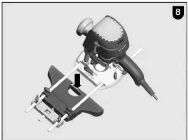
To provide a larger bearing surface, a stop web can be inserted into the parallel guide fence:
- Remove one of the two stop webs at the underside of the parallel guide fence.
- Insert the stop web into the device on the parallel guide fence intended for this (see Fig. 8). The second stop web serves as spare.
6.5.3 Milling with template guide
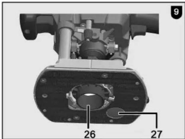
The template guides (∅ 20, 30 and 40 mm) can be used to mill shapes according to templates. The template guides are included in the scope of supply. After the reduction plate has been removed, the template guide 26 (Fig. 9) is inserted in the base plate 14 (Fig. 1), turned clockwise up to the stop and clamped with the wing screws. Design the template so that there is an adequate contact surface for the router base plate to guarantee a safe guidance of the machine. The template must be thicker than the collar length of the template guide.
In addition, it is possible to use a large number of different inch template guides with screw connection. The template guide adapter is included in the scope of supply.
6.5.4 Milling with reduced speed
The speed reduction is used for edge machining crosswise to the wood grain to reduce heat generation and friction. Failure to use this can lead to a reduction of the milling cutter service life or to burn marks on the workpiece.
Press the speed reduction button 6 (Fig. 1) to reduce the speed (reduction by 30%). The speed reduction is reset by pressing the speed reduction button 6 again; the machine runs in normal operation again.
6.5.5 Milling with adapter sleeve
If an end milling cutter (diameter 6 mm or 1/4") is to be used for milling, an adapter sleeve must be used with open tool clamp. Push the adapter sleeve completely into the collet and push in the milling cutter up to the minimum clamping depth. Pay attention that the adapter sleeve is free of grease.
6.5.6 Milling with guide rail
When a guide rail is used, the groove in the machine's base plate is placed onto the guide web of the guide rail.
While doing so, the machine's base plate is projecting beyond the guide rail. Now use the extraction adapter for the guide rail that is included in the scope of supply to ensure safe guidance on the guide rail.
It is also possible to position the machine against the edge of the guide rail, opposite the splinter guard, and to guide it in this manner.
An extended working application with the guide rail is for instance the use of the milling adapter LO-FA for pocket milling. The milling adapter is an optional accessory (see chapter 10).
6.5.7 Milling with support foot
The support foot 27 (Fig. 9) can in addition be used for template milling. With the wing screw 12 (Fig. 1), the support foot can be set to a depth up to 30 mm to ensure secure guiding of the machine on different material thicknesses.
7 Service and maintenance

Danger
Pull the power plug during all service work.
MAFELL machines are designed to be low in maintenance.
The ball bearings used are greased for life. When the machine has been in operation for a longer period of time, we recommend to hand the machine in at an authorised MAFELL customer service shop for inspection.
7.1 Cleaning the collet
- Use a ∅ 6 mm round bar (see Fig. 4) and push it through the bore in the fan housing.
- Turn the tool clamp until the round bar engages and blocks the tool clamp.
- Use a ring or open-ended wrench AF19 to open the clamping sleeve (clockwise direction of rotation, left-hand thread) until you can remove milling cutter, clamping sleeve and collet.
- Clean the collet with a conventional grease-dissolving cleaner.
- Re-insert the clamping sleeve with collet and milling cutter and re-tighten the clamping sleeve (counterclockwise direction of rotation, left-hand thread).
- Pull off the round bar.
7.2 Replacing the O-ring in the clamping sleeve
- Remove the milling cutter from the collet. See also Chapter 5.3 Clamping of milling tools.
- Remove the damaged O-ring with needle-nosed pliers.
- Insert a new O-ring into the groove of the collet.
- Reclamp the milling tool.
7.3 Storage
Clean the machine thoroughly if the machine is not used for a longer period of time. Spray blank metal parts with a rust-proofing agent.
8 Visual signal indication of operating condition
The visual output signals on the LED display indicate the operating condition of the machine:
| LED display | Operation / state of the machine |
| Blue (permanent) | Normal operationVariable bar value / variable bar display |
| Blue (flashing) | Throttled operationTo quit, press the speed reduction button again. |
| Red (flashing) | Cooling mode activeThe bar value corresponds to the expected remaining cooling mode run time. On reaching the cooling temperature, the machine is switched off and the display changes to permanent red. |
| Red (permanent), all bars are lit up in red | General error that can be eliminated by the operator:- Cooling mode completed- Excess temperature- Restart protection- Blocking switch-off |
| Display off | Defect at the machineSerious error or power failure.Take the machine to the MAFELL customer service repair shop or have it checked by a skilled electrician. |
9 Troubleshooting

Danger
Determining the causes for existing defects and eliminating these always requires increased attention and caution. Pull the mains plug beforehand!
Some of the most frequent defects and their causes are listed in the following chart. In case of other defects, please contact your dealer or the MAFELL customer service directly.
| Defect | Cause | Elimination |
| Machine cannot be switched on | No mains voltage | Check the power supply and/or press the main switch |
| Carbon brushes worn | Take the machine to the MAFELL customer service repair shop or have it checked by a skilled electrician | |
| Machine switches off automatically during idling | Mains failure | Ensure power supply, release switch trigger and press again |
| Cooling mode completed | ||
| Machine stops while milling | Excess temperature | Switch on machine and allow to cool in cooling mode |
| No mains voltage | Check mains-side pre-fuse | |
| Defect at the machine Cause must be determined by the customer service. | Take the machine to the MAFELL customer service repair shop or have it checked by a skilled electrician. | |
| Overload switch-off | Switch the machine on again | |
| Speed decreases during milling | Excessive chip removal | Reduce chip removal |
| Feed rate too fast | Reduce feed | |
| Blunt milling cutter | Grind or replace milling cutter | |
| Wrong speed | Wrong speed level set, speed reduction button is pressed (LED display flashes) | Adjust level and increase speed; adjust speed by means of speed button below the LED display |
| Excessive speed, soft start or speed control missing, braking no longer possible | Defective electronic system Cause must be determined by the customer service. | Take the machine to the MAFELL customer service repair shop or have it checked by a skilled electrician. |
| Unclean milling pattern | Blunt milling cutter | Grind or replace milling cutter |
| Uneven feed, wrong speed | Mill with constant pressure and reduced feed, adjust speed | |
| Milling cutter moves up/down in the collet or stops | Collet soiled O-ring in collet damaged | Clean collet and replace O-ring |
| Burn marks on the milled surfaces | Milling cutter unsuitable for the work step or blunt, wrong speed, feed rate too low | Grind or replace milling cutter Adjust speed and feed |
| Machine does not brake | Braking has taken place more than four times within a time period of 45 seconds. Brake lock is active. | After expiry of 45 seconds from the first braking, another braking is released. To avoid a brake lock, increase the brake interval to at least 10 seconds. |
10 Optional accessories
- Adapter sleeve ∅ 8 / ∅ 6 mm Order No. 207946
- Adapter sleeve ∅ 8 / ∅ ¼ " Order No. 207947
- LO-FA milling adapter Order No. 207200
- Template guide ∅ 17 mm Order No. 209851
- Template guide ∅ 24 mm Order No. 209850
- Guide rails F80 (0.8 m long) Order No. 204380
- Guide rails F 110 (1.10 m long) Order No. 204381
- Guide rails F 160 (1.60 m long) Order No. 204365
- Guide rails F 210 (2.10 m long) Order No. 204382
- Guide rails F 310 (3.10 m long) Order No. 204383
- Guide rails F80-LR Order No. 207600
- Guide rails F160-LR Order No. 207601
- Rail bag F 160 Order No. 204626
- Rail bag kit F160/160 consisting of: Order No. 204805
(2x F160 + connecting piece F-VS +2x tension clamps F-SZ 180MM + rail bag) - Rail bag kit F80/160 consisting of: Order No. 204749
(F80 + F160 + connecting piece F-VS + sliding bevel F-WA + 2 tension clamps F-SZ 180 MM + rail bag) - End caps F-EK (2 pieces) Order No. 205400
- Adhesive profile F-HP 6.8M Order No. 204376
- Splinter guard F-SS 3.4 m Order No. 204375
- Backlash stop F-RS Order No. 202867
- Tension clamp F-SZ 180MM Order No. 207770
- Connecting piece F-VS Order No. 204363
- Angle fence F-WA Order No. 205357
11 Exploded drawing and spare parts list
The corresponding information in respect of spare parts can be found on our homepage: www.mafell.com
Sommaire
line
| Time (min) | Number di giri in giri/min | |---|---| | 1 | 10000 | | 6 | 24000 | | 6 | 8000 | The chart displays a single data series: Line 1 (labeled 1) shows a steep linear increase from 10000 to 24000; Line 2 (labeled 2) shows a moderate linear increase from 10000 to 17000; Line 3 (labeled 3) remains constant at 8000 throughout. The chart lacks a title or axis labels but visually represents a trend or comparison across the two series.line
| X | Y (Prědk. obr. / obr./min) | |---|---| | 1 | 10000 | | 6 | 24000 | | 6 | 8000 | The chart displays a single line representing the predicted value for each series (labeled 1, 2, and 3). The x-axis ranges from 1 to 6, and the y-axis ranges from 6000 to 24000. The series '1' is marked with a circle, '2' with a square, and '3' with a circle. The '3' series is not explicitly labeled but appears at the bottom of the plot.MAFELL AG
Beffendorfer Straße 4, D-78727 Oberndorf / Neckar
Telefon +49 (0)7423/812-0
Internet:
E-Mail:
Fax +49 (0)7423/812-218
www.mafell.de
mafell@mafell.de

- WARNUNG
- AVERTISSEMENT
- GB - EC Declaration of Conformity
- Signs and symbols
- Product information
- Manufacturer's data
- Machine identification
- Technical data
- Emissions
- Danger
- Noise emission specifications
- Vibration specifications
- Shafts of the milling cutters
- Scope of supply
- Safety devices
- Use according to intended purpose
- Residual risks
- Safety instructions
- General instructions:
- Do not use:
- Instructions on the use of personal protective equipment:
- Instructions on operation:
- Stationary use:
- Instructions on service and maintenance:
- Layout
- Depicted components (see Fig. 1 and 2)
- Setting / adjustment
- Mains connection
- Chip and dust extraction
- Clamping of milling cutters
- Clamping
- Unclamping
- Operation
- Initial operation
- Switching on and off (see Fig. 1)
- Short operation
- Continuous operation
- Motor protection
- Speed adjustment
- Speed normal operation
- Speed throttled operation
- Speed cooling mode
- Milling depth adjustment
- Column clamping
- Revolving depth stop
- Adjustment of milling depth according to scale
- Fine adjustment of milling depth
- Work instructions
- Plunge milling
- Milling with parallel guide fence
- Conversion:
- Milling with template guide
- Milling with reduced speed
- Milling with adapter sleeve
- Milling with guide rail
- Milling with support foot
- Service and maintenance
- Cleaning the collet
- Replacing the O-ring in the clamping sleeve
- Storage
- Visual signal indication of operating condition
- Troubleshooting
- Optional accessories
- Exploded drawing and spare parts list
- Sommaire
Brand : Mafell
Model : LO 55
Category : Milling machine