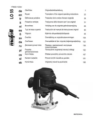
LO 65 Ec - Milling machine Mafell - Free user manual and instructions
Find the device manual for free LO 65 Ec Mafell in PDF.

| Product Type | Portable Router (Plunge Router) |
| Brand | Mafell |
| Model | LO 65 Ec |
| Power Supply Voltage | 230 V ~, 50 Hz |
| Power Consumption | 2600 W |
| No-Load Speed | 10 000 - 22 000 min⁻¹ |
| Plunge Depth | 0 - 65 mm |
| Depth Stop Turret | 3 levels |
| Tool Holder | Collet chuck Ø 6-12 mm and Ø 1/2", adapter M12 x 1 (M10) |
| Extraction Connection Diameter | 35 mm |
| Weight | 6.9 kg |
| Standard Equipment | Parallel guide, 30 mm copying ring, 8 mm collet chuck, M12 x 1 adapter, turret stop, 4 m cable, dust extraction hood, service tool, instruction manual, safety booklet |
| Sound Pressure Level | LPA = 71 dB(A), uncertainty 3 dB(A) |
| Sound Power Level | LWA = 82 dB(A), uncertainty 3 dB(A) |
| Hand-Arm Vibration | 3.3 m/s² |
| Protection Class | II (double insulation) |
| Workable Materials | Solid wood, wood-based panels (particleboard, plywood, plastics, MDF) |
| Main Functions | Plunge routing, routing with parallel guide, routing with template (copying ring), electronic speed control, electronic brake |
| Maintenance | Regular cleaning, greasing of lubrication points with special Mafell grease (ref. 049040), replacement of carbon brushes by an authorized service center |
| Safety | Base plate, handles, control device, motor cover, automatic overload shut-off, spindle lock |
| Spare Parts / Repairability | Spare parts available (collets, adapters, rings, etc.), exploded view at www.mafell.com, servicing recommended by an authorized service center |
| Optional Accessories | Guide rails (F80, F110, F160, F210, F310), guide stop, copying rings (20, 27, 40 mm), additional collet chucks, adapter for M10 router bits, guide system kit, clamps |
Frequently Asked Questions - LO 65 Ec Mafell
User questions about LO 65 Ec Mafell
0 question about this device. Answer the ones you know or ask your own.
Ask a new question about this device
Download the instructions for your Milling machine in PDF format for free! Find your manual LO 65 Ec - Mafell and take your electronic device back in hand. On this page are published all the documents necessary for the use of your device. LO 65 Ec by Mafell.
USER MANUAL LO 65 Ec Mafell
Please read all safety instructions and directions. Failure to comply with the safety instructions and directions can cause electric shock, fire and/or serious injuries. Please retain all safety instructions and directions for future reference.
AVERTISSEMENT
GB - EC Declaration of Conformity
We herewith confirm that the machine LO 65 Ec complies with the EU directives quoted. The standards listed were used for design and construction. Empowered person for the configuration of the technical documents: Mafell AG
CZ - PROHLASENI O SHODE
Timo prolasujeme, ze stroj LO 65 Ec splnjupe Pokyny uvedenych smemic EU. Pn pianovani a sestaveni byly vyuzity uvedene normy. Za sestaveni technickych podkladu zoypadova: Mafell AG
SLO - ES izjava o skladnosti
S tem Izjavjamo, da stoj LO 65 Ec ustreza navedenim direkivam EU. Pri konstrukcij in izdelavi so uporabljeni našeti standardi Za sestavo tehnicine dokumentaci je pooblašeno podjetje: Mafell AG
1 Signs and symbols 18
2 Product information 18
2.1 Manufacturer's data 18
2.2 Machine identification 18
2.3 Technical data 19
2.4 Emissions 19
2.5 Scope of supply 19
2.6 Safety devices 20
2.7 Use according to intended purpose 20
2.8 Residual risks 20
3 Safety instructions 20
4 Setting/Adjustment 21
4.1 Mains connection 21
4.2 Chip extraction (see Fig. 6) 21
4.3 Clamping of milling cutters (see Fig. 1 and 2) 22
4.4 Collet change (see Fig. 3) 22
4.5 Assembly and disassembly of the adapter for router bit with female thread (see Fig. 1 and 3) 22
5 Operation 22
5.1 Initial operation 22
5.2 Speed adjustment (see Fig. 1) 23
5.3 Milling depth adjustment (see Fig. 1) 23
5.4 Work instructions 23
6 Service and maintenance 24
6.1 Storage 24
7 Troubleshooting 25
8 Optional accessories 26
9 Exploded drawing and spare parts list 27
1 Signs and symbols

This symbol is found in all places where you will find information for your safety.
Non-compliance with these instructions may result in very serious injuries.

This symbol indicates a potentially hazardous situation.
If this situation is not avoided, the product or objects in its vicinity may get damaged.

This symbol indicates tips for the user and other useful information.
2 Product information
for machines with product no. 91C701, 91C720, 91C721, 91C750, 91C751
2.1 Manufacturer's data
MAFELL AG, Beffendorfer Straße 4, D-78727 Oberndorf / Neckar, Phone +49 (0)7423/812-0, Fax +49 (0)7423/812-218, e-mail: mafell@mafell.de
2.2 Machine identification
All details required for machine identification are available on the attached rating plate.

Protection class II

CE symbol to document compliance with the basic safety and health requirements according to Appendix I of the Machinery Directive.

For EU countries only
Do not dispose of electric tools together with household waste material!
In accordance with the European directive 2002/96/EC on waste electrical and electronic equipment and transposition into national law, obsolete electrical tools must be collected separately and recycled in an environmentally-compatible manner.

To reduce the risk of injury, please read the operating instructions.
2.3 Technical data
| Universal motor | 230 V~, 50 Hz |
| Input power continuous operation | 2600 W |
| Milling depth adjustment with fine adjustment | 0 - 65 mm (0- 17/16 in.) |
| Revolving depth control turret | 3-stage |
| Tool fastening: | |
| with collets | Ø 6 – 12 mm and Ø 1/2" |
| or with adapter for router bit | M 12 x 1 (M 10) |
| Idling speed | 10000 - 22000 rpm |
| Connection diameter at extraction hood | 35 mm (1 3/8 in.) |
| Weight without mains cable | 6,9 kg (15.2 lbs) |
2.4 Emissions
The declared noise emission values have been measured in accordance with DIN EN 62841-1 and may be used for comparing the tool with another and also in a preliminary assessment of exposure.

Danger
The noise emissions during actual use of the power tool can differ from the declared values depending on the ways in which the tool is used especially what kind of workpiece is processed.
Always wear hearing protection, even when the power tool ist running idle in addition to the trigger time!
2.4.1 Noise emission specifications
Noise emission values determined according to EN 62841-1 and EN 62841-2-17:
| Sound pressure level | LPA=71 dB (A) |
| Uncertainty | KPA=3 dB (A) |
| Sound power level | LPA=82 dB (A) |
| Uncertainty | KPA=3 dB (A) |
The noise measurement was recorded using the tool included in the standard equipment.
2.4.2 Vibration specifications
The typical hand-arm vibration is 3.3m / s^2
2.5 Scope of supply
| Router LO 65 Ec MaxiMax | LO 65 Ec MidiMAX |
| Art.-No. 91C701, 91C720, 91C721 | (specially suited for template milling) |
| 1 parallel stop | Art.-No. 91C750, 91C751 |
| 1 template guide Ø 30 mm | 1 template guide Ø 30 mm |
| 1 collet Ø 8 mm (Ø 1/2" - GB) | 1 adapter for router bit M 12 x 1 |
1 adapter for router bit M 12 x 1
1 revolving depth control turret
1 connection cord 4 m
1 extraction hood
1 operating tool
1 operating manual
1 folder "Safety instructions"
2.6 Safety devices

Danger
These devices are required for the machine's safe operation and may not be removed or rendered inoperative.
Before operating the machine, check the safety devices for function and possible damage. Do not use the machine with missing or ineffective safety devices.
The machine is equipped with the following safety devices:
- Base plate
- Handles
- Switch device
- Motor cover
2.7 Use according to intended purpose
The MAFELL router LO 65 Ec is exclusively intended for milling of solid wood and panel materials such as chip board, coreboard, synthetic board and MDF-board using HSS or TCT milling cutters.
Any other use than described above is not permissible. The manufacturer cannot be held liable for any damage arising from such other use.
So as to use the machine as intended, comply with the operating, maintenance and repair instructions specified by Mafell.
1 extraction hood
1 connection cord 4m
1 operating tool
1 operating manual
1 folder "Safety instructions"
2.8 Residual risks

Danger
Even if used in accordance with its intended purpose and despite conforming with the safety instructions, residual risks caused by the intended use that can lead to health consequences will always remain.
- Touching the running milling cutter or the cap nut.
- Breakage of the milling cutter and risk of the milling cutter or pieces of the milling cutter being hurled away.
- Backlash of the machine or the workpiece.
- Hearing can be impaired when working for long periods without ear protectors.
- Emission of harmful wood dusts during longer operation without extraction.
3 Safety instructions

Danger
Always observe the following safety instructions and the safety regulations applicable in the respective country of use!
General instructions:
- Children and adolescents must not operate this machine. This rule does not apply to young persons receiving training and being supervised by an expert.
-
Never work without the protection devices prescribed for the respective operating sequence and do not make any changes to the machine that could impair safety.
-
When operating the machine outdoors, use of an earth-leakage circuit-breaker is recommended.
- Damaged cables or plugs must be immediately replaced. Replacement may only be carried out by Mafell or an authorised MAFELL service workshop in order to avoid safety hazards.
- Avoid sharp bends in the cable. Especially when transporting and storing the machine, do not wind the cable around the machine.
- Clothes and hair must be worn so that they cannot come into contact with the milling cutter and milling spindle.
- Only use sharp and undamaged milling cutters. You will achieve improved surfaces and reduce the danger of backlash.
- Before starting up, check the tight seat of the milling cutter and its correct running.
- Only use milling cutters approved for manual feed.
- Only begin milling the workpiece when the milling cutter has achieved its full speed.
- Always lead the connecting cable away from the machine to the rear while milling.
- Always mill in counter direction while working on edges with larger tools.
- Only put down the machine after switching off once the milling cutter has come to a standstill or unscrew the clamping for the automatic reverse stroke on the machine and lock the latter again.
Instructions on the use of personal protective equipment:
- The noise pressure level at the ear generally exceeds 85 dB(A). Operators should therefore wear ear protectors.
- Always wear protective goggles during milling.
- You should wear a dust mask to prevent any damage to health.
Instructions on operation:
- Never reach into the working range of the milling cutter or underneath the base plate while the machine is running.
- Firmly hold onto the machine with both hands already before switching it on.
-
Whenever possible, secure the workpiece against slipping, e.g. with screw clamps.
-
Milling cutters must be replaced in good time, as blunt milling cutters do not only increase the danger of backlash, but also place an unnecessary strain on the motor. The milling cutters must be clamped in accordance with 4.3.
- Examine the workpiece for foreign objects. Do not mill into metal parts, e.g. nails (danger of backlash).
- The power plug must be pulled before replacing tools, making adjustments and repairing malfunctions (this also comprises removing jammed chips).
Instructions on service and maintenance:
- Regularly cleaning the machine, especially the adjusting devices and guides, constitutes an important safety factor.
- Only original MAFELL spare parts and accessories may be used. Otherwise the manufacturer will not accept any warranty claims and cannot be held liable.
4 Setting / Adjustment

Danger
When changing the tool, beware of the sharp blades of the milling cutter.

Avoid contact of milling cutters with machine parts when using milling cutters with a cutting diameter larger than the template guide or base plate opening. For this purpose, you can use the return stroke limit, see chapter 5.3.2
4.1 Mains connection
Prior to commissioning make sure that the mains voltage complies with the operating voltage stated on the machine's rating plate.
4.2 Chip extraction (see Fig. 6)
Connect the machine to a suitable external dust extractor during all work generating a considerable amount of dust. The air velocity must be at least 20m / s (65.6 ft/sec.).
The internal diameter of hose connector is 35mm (1 3/8 in.).
4.2.1 Assembly of the extraction hood
Place extraction hood 505 onto base plate 3 and turn it clockwise until it engages (Fig. 6).
4.2.2 Disassembly of the extraction hood
Press ratchet lever 4 and turn extraction hood 505 anticlockwise (Fig. 6).
4.3 Clamping of milling cutters (see Fig. 1 and 2)
The machine can be placed onto the motor cover to make replacing the milling cutter easier. The router is equipped with a precision collet 8 mm ( 1/2^* * on model GB). It is possible to fasten milling cutters with corresponding shaft diameter in this collet. The adapter that is included in the supply facilitates the fastening of milling cutters with female thread M 12 x 1.
Clamping

Never tighten the cap nut without fitted tool as this may damage the collet.
- Push the clean milling cutter shaft A as far as possible into the open collet 510.
- Push the index bolt 31 to lock the cutter spindle 27.
- Tighten cap nut 37 by first turning it clockwise by hand and afterwards by means of a flat spanner of wrench size 22. It is not necessary to regrip with the flat spanner. Simply turn back the cutter spindle by 90^ after you have unscrewed the index bolt and relock it with the index bolt.
Unclamping
- Push the index bolt 31 to lock the milling spindle 27.
- Release the lock nut 37 by turning it anticlockwise with an open-ended wrench AF22.
- Remove the router bit shaft A from the open collet 510.
4.4 Collet change (see Fig. 3)
Turn cap nut 37 from cutter spindle 27 to replace the collet. The collet 510 hangs in the cap nut. You can release the collet from the cap nut by forceful tilting and
pulling. Forceful pushing causes the collet to engage audibly in the cap nut.

Before installing it, clean the cutter spindle cone and the collet. Only mount collets in the cutter spindle that have engaged correctly in the cap nut.
4.5 Assembly and disassembly of the adapter for router bit with female thread (see Fig. 1 and 3)
Assembly
Instead of collet 510, insert the adapter into cutter spindle cone 27 and tighten it with cap nut 37. The milling cutters can be fastened on the protruding end of the thread.
Disassembly
- Lock the cutter spindle by pressing index bolt 31.
- Slightly unscrew the milling cutter at the adapter.
- Keep the index bolt depressed and unscrew the tensioning nut with a flat spanner of wrench size 22.
- Manually screw the cap nut onto the milling cutter collar.
- Twist the cap nut and the milling cutter against each other using the flat spanner. By doing so, you will pull the adapter from the cone.
- You can screw off the parts by hand.
5 Operation
5.1 Initial operation
Personnel entrusted to work with the machine must be made aware of the operating instructions, calling particular attention to the chapter "Safety instructions".

- Before starting up, check the tight seat of the router bit and its correct running.
- When milling properties change, check the cutting elements of the milling cutter.
5.1.1 Switching on and off (see Fig. 1)

Danger
Only switch on the machine if the milling cutter has no contact with the workpiece.
- Switching on: Press rocker switch 42 at the end designated with I.
- Switching off: Press rocker switch 42 at the end designated with O. The electronic brake causes the machine to come to a standstill very quickly.
5.2 Speed adjustment (see Fig. 1)
Which speed has to be set for which milling cutter- and material can be gathered from the depicted diagram and from the front of the machine.
| n x1000/min | ||||
| ∅10-20 | 18-22 | 18-22 | 20-22 | 14-22 |
| ∅20-30 | 14-18 | 16-20 | 18-20 | 12-20 |
| ∅30-40 | 12-16 | 14-18 | 12-18 | 10-18 |
| ∅40-50 | 10-14 | 10-14 | 10-14 | 10-16 |
The electronic system keeps the set speed constant. In addition, the electronic system adjusts the motor down in case of overload, i.e. the tool will stop. The machine must then be switched off. Switch on the machine again afterwards and continue to work with reduced feed speed.

Danger
Do not work with the router if the electronic system is defective, as this may lead to excessive speeds.
5.3 Milling depth adjustment (see Fig. 1)
5.3.1 Clamping device
By turning handle 25 clockwise you can lock the machine at any milling depth.
5.3.2 Return stroke limit
To avoid unnecessary empty strokes, you can reduce the stroke to the required length by adjusting knurling nut 28.
5.3.3 Revolving depth control turret
The revolving depth control turret 12 can be used to set three different milling depths. The longest of the stop screws 85 is set to the smallest milling depth while the shortest stop screw 83b is set to the largest milling depth.
5.3.4 Adjustment of milling depth according to scale
- Clamp the milling cutter and place the machine onto the workpiece.
- Unscrew the clamping and contact the workpiece surface with the milling cutter. Then clamp the machine again.
- Adjust depth stop 45 up to the stop screw.
- Set the top edge of the slidable needle 19 on the depth stop to the zero point of scale 43.
- Set the depth stop to the desired milling depth and clamp it with the clamping arm 68c.
- The empty stroke can be reduced to approx. 10 mm with knurling nut 28.
If you release the clamping at the machine, the reverse stroke will be carried out automatically.
5.3.5 Fine adjustment of milling depth

A fine adjustment of the milling depth can be achieved by turning adjusting nut 30. One turn of the adjusting nut causes a milling depth adjustment of 1mm
5.4 Work instructions

Hold onto the machine with both hands during operation.
5.4.1 Plunge milling
While milling ensure that the workpiece is secured, that the router with base plate 3 and / or the limit stops rests as even as possible and with an as large as possible surface against the workpiece and that large depths are milled in stages. Once you have set the milling cutter speed, firmly hold onto the machine with both hands and switch on the machine. Plunge into the material up to the limit stop with an even feed and then lock the machine. Only mill in counter direction.
5.4.2 Milling with parallel stop (see Fig. 1)
Parallel stop 13 is used to accurately guide the machine along a straight workpiece edge.
Conversion:
- Push the guide rods 36 laterally into the prism-shaped openings of the base plate.
- Roughly set the parallel stop to the desired distance to the milling cutter and tighten the wing screws 68a.
- Knurling screw 34 permits you to accurately set the distance to the milling cutter. Then tighten the wing screws 68b.
Adjust the sliding pads on the parallel stop
The sliding pads 15 can be pushed together to adjust the stop surface during processing of edge ends. To do so, unscrew cylinder-head screws 83a, 86 and set the sliding pads close to the milling cutter or push them together completely.
5.4.3 Milling according to template
With the template guide 507 (see Fig. 4) it is possible to mill shapes using self-made templates. Screw the template guide onto the underside of base plate 3
using the countersunk screws 77. The template must be wide enough to allow a secure guiding of the machine.
Before using a template guide for the first time (see Fig. 4), the two thin webs must be removed from the sliding surface of the base plate.
5.4.4 Milling with parallel stop and roller edge guide (see Fig. 5)
(also available as special accessories)
The roller edge guide B can be fastened on parallel stop 13 at the end of the screws using hexagon nuts C. With this guide it is possible to carry out milling work parallel to edges of any shape.
6 Service and maintenance

Danger
Pull the power plug during all service work.
MAFELL machines are designed to be low in maintenance.
The ball bearings used are greased for life. When the machine has been in operation for a longer period of time, we recommend to hand the machine in at an authorised MAFELL customer service shop for inspection.
Only use our special grease, order No. 049040 (1 kg tin) for all greasing points.
6.1 Storage
Clean the machine thoroughly if the machine is not used for a longer period of time. Spray blank metal parts with a rust-proofing agent.
7 Troubleshooting

Danger
Determining the causes for existing defects and eliminating these always requires increased attention and caution. Pull the mains plug beforehand!
Some of the most frequent defects and their causes are listed in the following chart. In case of other defects, please contact your dealer or the MAFELL customer service directly.
| Defect | Cause | Elimination |
| Machine cannot be switched on | No mains voltage or mains voltage too low | Have power supply checked by an electrician |
| Mains fuse defective | Have fuse replaced by an electrician | |
| Carbon brushes worn | Take the machine to a MAFELL customer service shop | |
| Machine switches off automatically during idling or stops during the milling process | Mains failure | Have mains-side pre-fuse checked by an electrician |
| Machine overloaded (Overcurrent shutdown) | Switch machine off and on again Reduce feed speed | |
| Speed decreases during milling | Excessive chip removal | Reduce chip removal |
| Excessive feed | Reduce feed | |
| Blunt router bit | Grind or replace router bit | |
| Excessive speed, soft start missing or speed control no longer possible | Defective electronic system | Take the machine to a MAFELL customer service shop |
| Unclean milling pattern | Blunt router bit | Grind or replace router bit |
| Uneven feed | Mill with constant pressure and reduced infeed | |
| Burn marks on the milled surfaces | Router bit that is unsuitable for the operating sequence or blunt | Grind or replace router bit |
| Machine switches off during operation | Voltage interruption (undervoltage shutdown) | Switch machine off and on again |
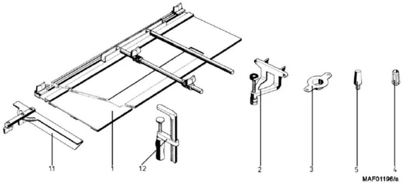
8 Optional accessories
1 - Guide track, CPL. Order No. 039100
1.1 - Sliding bevel, cpl. Order No. 038108
1.2 - Screw clamp Order No. 093249
2 -Roller edge guide, complete Order No.038987
3 - Template guide 20 mm Order No. 200693
3 - Template guide 27 mm Order No. 038988
3 - Template guide 40 mm Order No. 038989
4 - Collet 6 mm Order No.093257
4 - Collet 8 mm Order No.093256
4 - Collet 0 10 mm Order No. 093255
4 - Collet 012 mm Order No. 093254
4 - Collet 1 / 4^ Order No.093279
4 - Collet 01/2" Order No. 093276
5 -AdapterforrouterbitM10 OrderNo.039363
-Adapter for router bit with female thread M 12 x 1 Order No. 201575
- Template guide RD 30 Order No. 038971
- Stair string milling cutter Order No. 200500
LO-FA milling Adapter Order No. 207200
Guide rail F 80 Order No.204380
Guide rail F 110 Order No. 204381
Guide rail F 160 Order No.204365
Guide rail F 210 Order No. 204382
Guide rail F 310 Order No.204383
Single tension clamp Order No. 207776
Guide rail F 80-LR Order No.207600
Guide rail F 160-LR Order No.207601
Connecting piece packed F-VS Order No. 204363
Adhesive profile packed F-HP 6.8 m Order No. 204376
Splinter guard packed F-SS 3.4 m Order No.204375
Tension clamp packed F-SZ 180 mm (2 pcs) Order No. 207770
End caps packed F-EK Order No. 205400
Recoil stop packed F-RS Order No. 202867
Rail bag 160 Order No.204626
Rail bag kit F160/160 consisting of: 2 x F160 + connecting piece + 2 screw Order No. 204805 clamps + rail bag
Rail bag kit F80/160 with sliding bevel segment consisting of: F80 + F160 Order No. 204749
- connecting piece + sliding bevel + 2 screw clamps + rail bag
9 Exploded drawing and spare parts list
The corresponding information in respect of spare parts can be found on our homepage: www.mafell.com
Sommaire
Pierre de raccordement emb. F-VS Ref. 204363
Profil d'adherence emb. F-HP 6.8M Ref. 204376
Pare-éclats F-SS 3,4M Ref.204375
Pare-rebond emb. F-RS Ref. 202867
5.4.3 Fräsa after mall
LO-FA-frasadapter Best.nr.207200
Styrskena F 80 Best.nr.204380
Styrskena F 110 Best.nr.204381
Styrskena F 160 Best.nr.204365
Styrskena F 210 Best.nr. 204382
Styrskena F 310 Best.nr.204383
| enkel klämma | Best.nr. 207776 |
| Styrskena F 80-LR | Best.nr. 207600 |
| Styrskena F 160-LR | Best.nr. 207601 |
| Skarvstycke verp. F-VS | Best.nr. 204363 |
| Vidhäftningsprofil F-HP 6,8M | Best.nr. 204376 |
| Chipbrytare verp. F-SS 3,4M | Best.-Nr. 204375 |
| Klämmor verp. F-SZ 180MM (2 st.) | Best.-Nr. 207770 |
| Ändkappar verp. F-EK | Best.-Nr. 205400 |
| Återgångsstopp verp F-RS | Best.-Nr. 202867 |
| Styrficka F 160 | Art. nr. 204626 |
| Sats med skenväskor F160/160 bestäende av: 2 x F160 + skarvstycke + två skruvtvingar + skenfodral | Best.-Nr. 204805 |
| Sats med skenväskor F80/160 med vinkelanslag bestäende av: F80 + F160 + skarvstycke + vinkelfäste + två skruvtvingar + skenfodral | Best.-Nr. 204749 |

2.1 Producers informationer
MAFELL AG, Beffendorfer Straße 4, D-78727 Oberndorf / Neckar, Telefon +49 (0)7423/812-0, fax +49 (0)7423/812-218, e-mail mafell@mafell.de
He 6pocaiTe 3JIeKToHcTpymEHTbI B 6blTOBoMycop!
Cornacno Ebponeecko dnpekTbe 2002/96/EG o6 yctapeBux x3neKtpuecknx n 3neKtpoHHbIX npnbopax u aHaIOnuHbIM 3aKOHAM OTdeJbHbIX CTpaH, IcNoJIb3OBAHHbIE 3neKtpoIHCTpyMeHTbl DOJIxHbI CObipaTbcr OTdeJIbHO IN nepedabatbcra dna daJIbHeIwero nCpOJIb3ObaHn8 be3 yUep6a dna OkpykaIOSei cpebl.

IpoHTaTe HnCTpyKuNo No 3KcNpyatauN dny yMeHbSeHna OnaCHOCTn noJyHeHn TpaBM.
2.3 TexHHueckne xapaKTepeNCTIKN
4.2.2 DeMoHTaX BbITaXHOrO KOxya
HaXMMTe Ha φnKcaTopHbI pbUar 4 n nobepHnte BblTJxHOi KoxyX 505 npOTnB yacOBn CTpeJIKN (pnc. 6).
4.3 Kpennene Hne 0pe3bl (cM.pnc.1n2)
Для Лergо 3amehblфpe3bl yctpoiCTBO MOxHO yctahOBnTB Ha KpbIshky DnBraTeJIa. PuchoiФpe3ep o6OpydoBaH ToUhBIM ZaHROBbIM nATPOHOM 8 MM (0 1/2" npn nCn. dJa GB). B hem MoXHo KpeNTb Фpe3bl c COOTBeTcByuOuM dHaMeTpOM XBOCTOBnKa. BxoJusn B KomPNeKT nepexoDnK nO3BOJnEeT 3akpeNTb Фpe3bl c BHyTpEnHei pe3b6oM M 12 x 1.
3axmamHe

HnKoRda He 3aTayBaIte
HaKnDHyO raKy 6e3
yCTaHOBJIeHHOrO IHCTpyMeHTa,
HNaYe MoXHo IOBpeIITb
ZaHROBbI NaTPOH.
BctabnTe XBOCTOBK 4pe3bA KaK MOXHO daIbWe BOTKpbITbI ZaHROBbI NaTPOH.
- PnIXMnte 6oIIT 31, TTo6bl 3aФnkCnpOBaTb WnHdJIb Fpe3bl 27.
- IOBOPOTOM BnpaBO Chauana BpyHyu, a 3aTem poKOBbIM KIOHOM Ha 22 3aTaNHe HAKNHyO raKy 37. IepexBaT BTOpbIM RaeyHbIM KIOUOM He Tpe6yETc. IpoCTO NOBepHnTe UINHdIb φpe3bHa 90^ Ha3aI, nocJIe TORO KaK OcnaBnI 6oNTbI, IN CHOBA 3aΦNKcPyuTe ux.
Pa3KImaHne
HaxmTe Hndeknpyembl 60nt 31, TTo6bl 3aΦnkCpOBaTB UINHdJIb Fpe3bl 27.
Ocna6bTe haknHyro raKy 37, nobepHyB ee BJIeBO C nOMoIbIO BInNoHoro KInOya SW22.
- CHIMITE XBOCTOBNK φpe3bl A c OTKpbITOrO
caHROBOrO NaTpoHa 510.
4.4 CmeHa zauHroBoro naTpoHa (cm.pnc.3)
ДясMeHbI ZaHROBOrO NaTPOHa NOBepHnTe HaKnDHyu RaKy 37 Chn3y ShnHdEJIaФpe3bl 27. ZaHROBbI NaTPOH 510 BnCnT B HaNiDHOraKe. YTo6bl BbIHyTb ZaHROBbI NaTPOH n3 HaNiDHOraKn HAdo CnIbHO HaKnOHTb I NotaHyTB erO. CnIbHbIM HaxKaTneM 3aФнICUPyIe co UeJUcKOM ZaHROBbI NaTPOH B HaNiDHOraKe.

OuHCTnTe nepey uCTaHOBKO KOHyc
pe3epHoro 7nnHdEJa n
ZaHRObI NaTPOH. MoHTnpuyTe
TOJbKO npaBNbHO
3aФNkCnPoBaHHb B HaKnIDHO
raKe ZaHRObI NaTPOH B
UHNDeIb #pe3bl.
4.5 MoHTaX n DeMOHTaX nepexoHnKa dJa 0pe3bI c BHyTpehHei pe3b6oN (cM.pnc.1n 3)
MOHTAX
YcTaHOBInTe NepexOndHnK Ha MeTo cHaHROBOr OnatpoHa 510 B KOhyc WnHdEJIa Fpe3bI 27 n 3aTAHnTe ero HaknDho raKoN 37. Ha BbIdaHOeMcra KOHcpe pe3b6bl MoXHo 3aΦHKcnpOBaTb Fpe3y.
dEmoHTax
3aФИKcIpyTe HaxaTneM 6oNTa 31 WnHdJIb 0pe3bl.
Cnerka ocna6bTe 4pe3y Ha nepexoHnke.
OCTaBbTe 6oTn npKxatbIM n ocna6bTe 3axmHy0 raKy raeHbIM KNoyom Ha 22.
BpyHyIO 3aKpyTnTe HAKnDHyIO raIKy Do KpOMKn pe3bl.
- IOBepHnTe HAKnHyO raKy u φpe3y poKKBbIM KInoYOM Dpyr npotNB dpyra. TAKM o6pa3oM n3BJIeKnTe nepexoDnK n3 KOhyca.
- DeTaJIIMoXHIO OTKpyTNTb BpyHyIO.
5 3Kcnnnyataua
5.1 BBoD B 3KcnpnyatauH
DaHnyo HNCTpyKUIO NO 3KcPnPyatauIN CNeJeYET DOBecTN Do CBeDeHNA BCEX NIIU, KOTOpbIM NOpyuHo UnpaBHeHne MaunHO, PpueM Oco6oe BHMaHne CNeJyET o6paTtB Ha pa3dEIN ,PpabIna 6e3OnacHocTN".

- PpOBepbTe nepeB BBOOM B 3KcPnPyatauHIO npOuyHOCTb nocaKn fpe3bl ee ToUhbl XoJ.
- Pn n3MeHenn xapaKTeepNtIK ppe3epoBaHnI npOBepbTe peXyUne 3JIeMeHTbl ppe3epHOrO nHCTpyMeHTa.
5.1.1 BkIIOUeHne n BbIKIOUeHne (cM.pnc.1)

Onacho
BknouaTb MaunHy TOnbKO npn OTCyTCTBm KOHTaKaTc 3arOTOBKo.
BknoueHne:HaKMTe kaayounc npaXOK BbIKnOuateJ42B MeTe,0603NaueHHOMI.
BbIKIOueHne: HaxMITE KaayoUncra pbuXOK BbIKIOUaTeI 42 B MeCTe, 0603HaueHHOM O. 3a Cuet 3JIeKTPoHHoro TOPMO3a MaUNHa OCTaHaBJIINBaETcMAKcIMMaJIbHO 6bICTPO.
5.2 PerynpoBka yactotbI BpaueHna (cm.pnc.1)
Kakyu yactoty BpaueHn yctHaBnBaTb B 3aBncmocTN OT dAmetpa fpe3bl N MaTePnana -cm. Ha npBedeHHO CXeMe n Ha nepeDHe CTOpOHe MaunHbl.
| n x1000/min | ||||
| ∅10-20 | 18-22 | 18-22 | 20-22 | 14-22 |
| ∅20-30 | 14-18 | 16-20 | 18-20 | 12-20 |
| ∅30-40 | 12-16 | 14-18 | 12-18 | 10-18 |
| ∅40-50 | 10-14 | 10-14 | 10-14 | 10-16 |
3NeKtpoHnKa NOpDepXnBaet NOCTOHHoHy UcTaHOBJIeHHyU YoCTOTy BpaueHn.
Kpome TOrO, 3JIeKTPoHnka peryInpyeT DBuRaTeIb npi neperpy3Ke, T.e. INHCTpyMeHT OCTaHaBnBaETCr. 3aTeM yCTPOINCTBO Heo6XODIMOBbIKIOUHTb. ChOBA BKNIOUHTe MaunHy n npoDoJxKaIte pa60TaTb Ha COKpaueHHoC KOpOCTN NOaHi.

Onacho
He pa6oTaIe c pyuHbIM cppe3epom,ecn3JIeKtpOnHka HEnCnpaBHa, NOCKOJbKy MoXET 6bITb Ype3BbUaHNo 3aBbIWeHa qactota BpaSeHna.
5.3 YcTaHOBka rIy6HbI cpe3epoBaHnA (cm.pnc. 1)
5.3.1 3axmHoe yctpoCTBO
BpaueHnem BnpaBo pyuKn 25 MoXHo fNkCnpoBaTb MaunHy Ha JIO6oI rIy6nHe fpe3epoBaHnI.
5.3.2 OrpaHnueHne o6paTHoro xOda
YTo6bI n36eXaTb HeHyXHOrO XoNoCToro XoJa, MoXHo COKpaTntB erO peryIInpOBKoR raiKn c npOJbHO HaKaTko 28 Ha Heo6xOdMbI pa3mep.
5.3.3 PeBoNbBepHbI ynp
PebolbBepHbIM ynpom 12 MoXHO yCTaHOBtB TpN pa3nUHbIe rJy6nHbI φpe3epoBaHnA. Cambi IINHHbI IN3 ynpHbIX BnHTOB 85 yCTaHOBtE Ha HAnMeHbSyIO rJy6nHy φpe3epoBaHnA, Cambi KOpOTkn 83b -Ha MaKcImMaNbHyO rJy6nHy φpe3epoBaHnA.
5.3.4 YcTaHOBka rIy6uHbI 0pe3epoBaHn no uKaane
3aKpeNITe 0pe3y u yCTaHOBNTe MaunHy Ha 3arOTOBky.
OTcoeINHnTe orpaHnHTeJIb n npNKoCHnTEcb HCTpyMeHTOM K NOBepXHOCTn 3aTOBKn. 3aTeM CHOBA 3aKpeNITe orpaHnHTeJIb.
- Iepemecntte ynp orpaHueHnra 1y6nHb 45 do ynpHoro BnHTa.
BepxHIO KpOMky NOdBnXHOI CTpeKN 19 Ha ynpoe Iy6uHbI yCTaHOBInTe Ha HJNeByTOuy Ky uKanbl 43.
- YctaHOBInTe ynp rIy6nHbHa Heo6xOIMyU0 rIy6nHy Φpe3epOBaHnN 3aФnkCpUte 3axmHbIM pbIarom 68c.
XoIOCTOxODMOXHO COKpaTHTbraIKoN C npOIOHBOH hakatKoN 28 npImepHo Ha 10 MM.
Ecni OTcoeINHHTb ORpaHnHTeJIb Ha yctpoiCTBe, BO3HNkaeT o6paTHbI XoJ.
5.3.5 ToHaKoppeKTHpOBKa rIy6HbI 0fpe3epoBaHnA.

ToHKaKorpeKTnPOBka rny6HbI
Φpe3epoBaHnA DoCTnRaeTcR
BpaueHnEm peyJInpOBOuHO
raKn 30.Odn H obopot
peyJInpOBOuHO raKn Bbl3bIBaET
peyJInpOBky rny6HbI
Φpe3epoBaHnHa 1 MM.
5.4 Yka3aHn no pa6oTe

YdepxBaTe MaunHy npn 3KcnnyatauOnn obemn pykAm.
5.4.1 Φpe3epoBaHne c yTaJIuBaHneM
Cnejte npn fpe3epoBAHn 3a TeM, yTo6bl 3arOTOBka 6bIa 3akpenHe, pyHOn fpe3ep pOBHo npIneral K Bo3MOxHO 6OJIbSei IIOUaDi NIIHTOJ OCHOBHn 3 n / nIy uNopAmn, a 6OJIb7Ara rIy6uHa fpe3epoBaIacb noCTeHNo. IocNe yCTAHOBKn YAcTObI BpaUeHn fpe3bl yDepXINBaIte MaunHy oBeIMn pykAmn n BkIIOChTe ee. PaBHomepHo nOrpy3ntecb Do yNopa B 3arOTOBky n 3aФNKcnpyIte yCTPOINCTBO. Fpe3epuTe TOJIbKO B nPOTIBONIOJXHOM HAnpaBJIeHN.
5.4.2 Φe3epoBaHnE c npaJIeIbHbIM ynpom (cM.pnc.1)
ДяTOUHOro BeDeHnMaUINbI BDoJI nprMoN KpOMKn 3aROToBKN NcNoJIb3yETc npaJIneJIbHbI ynop 13.
NepemOnTaK:
BCTaBbTe HnpaBnaHouIe 36 c6Oky B OTBePcTnBΦOpMe npN3MbIB NITte OCHOBaHnA.
- YctaHOBnTe napaJIeIbHbI ynp np6JIIN3IteIbHo Ha Heo6XoIIMoe pacCTOHaHe Do fpe3bl 3aTAHnTe 6apaWKOBbI BnHT 68a.
BHTOM c hakaTko34 moXHO OTpeYnIPOBaTb pacCToHHe Do ope3bl. 3aTeM 3aTaNITE 6apaKOBbI BVHT 68b.
IepemeueHne HappaBnaIOx NHeek Ha napaJIeIbHOM ynope
Negotovost K_PA = 3 dB (A)
Raven zvočne moči L_WA = 82 dB (A)
Negotovost K_WA = 3 dB (A)
Merjenje hrupa je bilo opravljeno s serijsko sodobavljenim orodjem.
2.4.2 Podatki o vibracijah
Tipicni tresljaj roke znaša 3,3 m/s².
2.5 Dobavni obseg
| Namizni rezkalinik LO 65 Ec MaxiMax | LO 65 Ec MidiMAX |
| Št. art. 91C701, 91C720, 91C721 | (posebej primeren za šablonsko rezkanje) |
| 1 vzporedni omejevalnik | Št. art. 91C750, 91C751 |
| 1 kopirni obroč Ø 30 mm | 1 kopirni obroč Ø 30 mm |