MM 2 - Multimeter BENNING - Free user manual and instructions
Find the device manual for free MM 2 BENNING in PDF.
| Product Type | Digital Multimeter |
| Brand | BENNING |
| Model | MM 2 |
| Display | LCD 3½ digit, 20 mm height, max 1999 |
| Number of measurements per second | 2.5 |
| Measurement functions | DC/AC voltage, DC/AC current, resistance, diode test, continuity test, capacitance, frequency |
| DC voltage ranges | 200 mV to 600 V, resolution 0.1 mV to 1 V, accuracy ±(0.5% + 2 digits) |
| AC voltage ranges | 200 mV to 600 V, resolution 0.1 mV to 1 V, accuracy ±(1.3% + 5 digits) (40-500 Hz) |
| DC current ranges | 200 µA to 20 A, resolution 0.1 µA to 10 mA, accuracy ±(1.0% to 2.0% + 2-3 digits) |
| AC current ranges | 200 µA to 20 A, resolution 0.1 µA to 10 mA, accuracy ±(1.5% to 2.5% + 3-5 digits) (40-500 Hz) |
| Resistance ranges | 200 Ω to 20 MΩ, resolution 0.1 Ω to 10 kΩ, accuracy ±(0.8% to 2% + 2-5 digits) |
| Diode test | Open circuit voltage max 3.2 V, measuring current max 1.5 mA, accuracy ±(1.5% + 5 digits) |
| Continuity test | Threshold resistance < 50 Ω, audible beep |
| Capacitance ranges | 2 nF to 200 µF, resolution 1 pF to 100 nF, accuracy ±(3.0% + 4 digits) |
| Frequency ranges | 2 kHz to 200 kHz, resolution 1 Hz to 100 Hz, accuracy ±(1.5% + 5 digits) |
| Power supply | 1 9 V battery (IEC 6 LR 61) |
| Battery life | Approximately 150 hours (alkaline) |
| Dimensions (without frame) | 175 x 84 x 31 mm |
| Dimensions (with frame) | 192 x 95 x 50 mm |
| Weight (without frame) | 340 g |
| Weight (with frame) | 550 g |
| Overvoltage category | CAT II 600 V, CAT III 300 V |
| Protection | Double insulation (class II), IP30 |
| Operating temperature | 0 °C to 50 °C (depending on humidity) |
| Storage temperature | -20 °C to +60 °C (battery removed) |
| Protective fuses | 1 A/500 V (ref. 749669) and 16 A/500 V (ref. 749770) fast-acting |
| Supplied accessories | Safety measuring leads (red/black 1.4 m), rubber holster, carrying case, 9 V battery, mounted fuses, user manual |
| Maintenance | Clean with dry cloth, no solvents; replace battery when symbol appears; replace defective fuses with identical parts |
Frequently Asked Questions - MM 2 BENNING
User questions about MM 2 BENNING
0 question about this device. Answer the ones you know or ask your own.
Ask a new question about this device
Download the instructions for your Multimeter in PDF format for free! Find your manual MM 2 - BENNING and take your electronic device back in hand. On this page are published all the documents necessary for the use of your device. MM 2 by BENNING.
USER MANUAL MM 2 BENNING
Multilingual manuals on included CD and at
BENNING MM 3
text_image
-1.08.0 OFF DC AC 20μF 200μF 200μA 200μA 200μA 2K Hz 20K Hz 200kΩ 20kΩ 200mV 20MΩ 200mV 600V 200V 2V 200mA 20mA 20mA 20mA 20mA 20mA 20mA 20mA 20mA 20mA 20mA 20mA 20mA 20mA 20mA 20mA 20mA 20mA 20mA 20mA 20mA 20mA 20mA 20mA 20mA 20mA - + + 20 A μAmA COM VΩ Hz MAX 10A cm. 28A 184w. F/65D MAX (58mA) P/65D CAT II MX NVR BENNING MM 3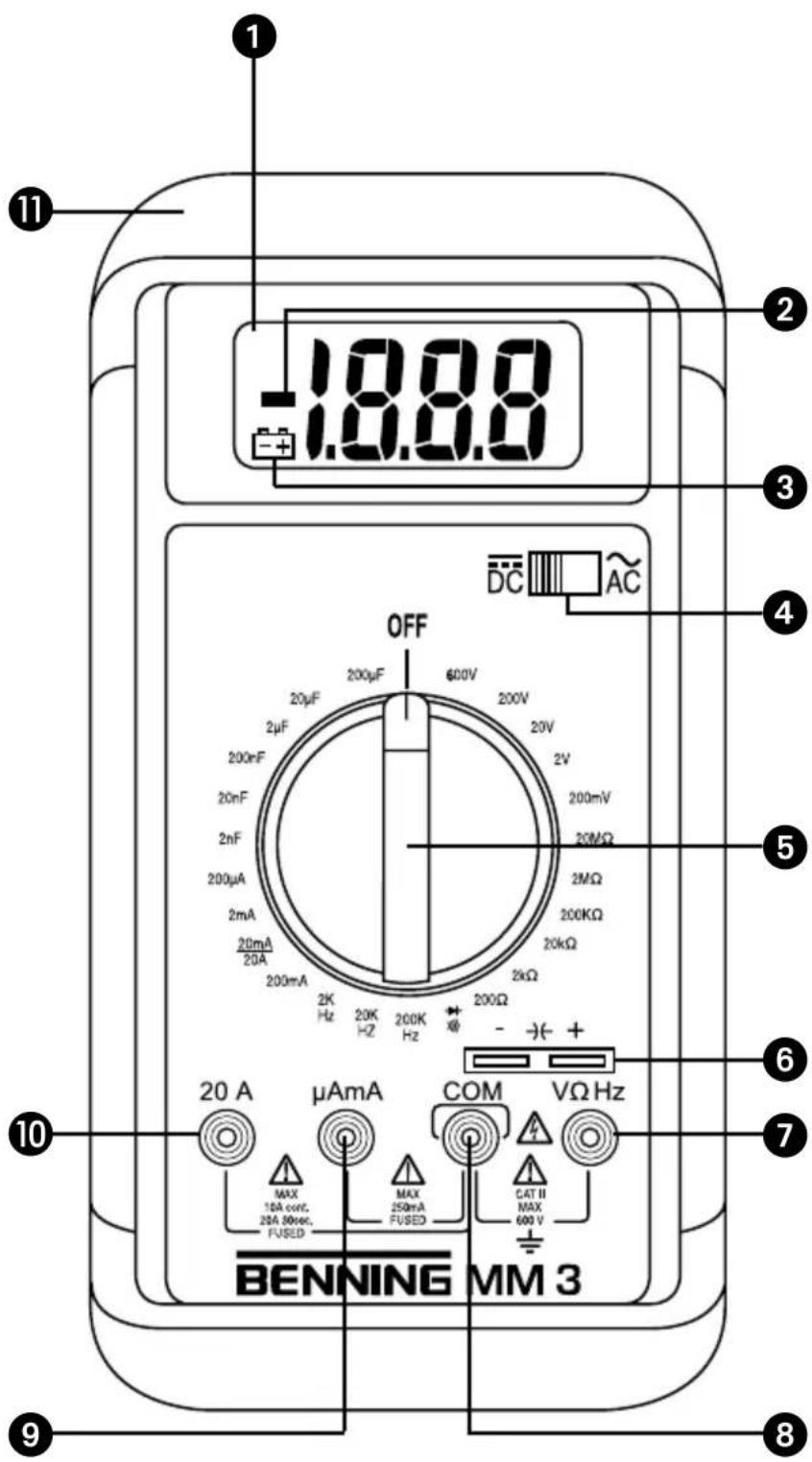
text_image
18.8.8 -18.8.8 OFF 200μF 600V 200V 20V 200mV 20MΩ 2MΩ 200kΩ 20kΩ 2K Hz 20K Hz 200K Hz - + 20 A μAmA COM VΩ Hz MAX 15A cc/Hz, 25A 50rec, FUSED MAX 250mA FUSED CAT II MAX 600 V BENNING MM 3Bild 1: Gerätefrontseite
Fig. 1: Front tester panel
Fig. 1: Panneau avant de l'appareil
Fig. 1: Parte frontal del equipo
Obr.1: Přední strana přístroje
ill. 1: Lato anteriore apparecchio
Fig. 1: Voorzijde van het apparaat
Rys.1: Panel przedni przyrządu
Imaginea 1: Partea frontală a aparatului
Рис. 1. Фронтальная сторона прибора
Fig. 1: Framsida
Res. 1: Cihaz ön yüzü
text_image
-18.88 BENNING AM 3 + - A BFig. 2: Direct voltage measurement
Fig. 2: Mesure de tension continue
Fig. 2: Medición de tension continua
Fig. 3: Alternating voltage measurement
Fig. 3: Mesure de tension alternative
Fig. 4: DC current measurement
Fig. 5: AC current measurement
Fig. 6: Resistance measurement
Fig. 8: Continuity Testing with buzzer
Fig. 9: Capacity Testing
Fig. 10: Frequency measurement
natural_image
Technical line drawing of a device casing with internal components and mounting holes (no text or symbols)Fig. 11: Battery replacement
Fig. 11: Cambio de pila
natural_image
Exploded view diagram of a multimeter with labeled components (no text or symbols on the diagram itself)Fig. 13: Winding up the safety test leads
Fig. 14: Erecting the BENNING MM 3
Fig. 14: Installation du BENNING MM 3
Digital Multimeter for
- DC voltage measurement
- AC voltage measurement
- DC current measurement
- AC current measurement
- Resistance measurement
- Diode testing
- Continuity testing
- Capacitance measurement
- Frequency measurement
Index of Contents
- Operating instructions
- Safety instructions
- Scope of delivery
- Meter description
- General Specifications
- Ambient Conditions
- Electrical Specifications
- Measuring with BENNING MM 3
- Maintenance
- How to use the protective rubber holster
- Technical data of the measuring accessories
12.Environmentalnote
1. Operating Instructions
This operating manual is intended for
- electrical professionals
- qualified electrotechnical persons
The BENNING MM 3 is designed for measuring in dry conditions. It must not be used on electrical circuits with a rated voltage greater than 600 V AC/DC (for details refer to "Ambient Conditions" section).
The following symbols appear in this manual and on the BENNING MM 3:

This symbol indicates dangerous voltage.

This symbol indicates warnings and cautions to be observed when using the BENNING MM 3 (refer to manual!)

This symbol on the BENNING MM 3 indicates that the BENNING MM 3 has double insulation (Protection Class II)

This symbol on the BENNING MM 3 indicates the unit contains built-in fuses.

This symbol appears in the display when the battery is low.

This symbol indicates the "Continuity testing" mode is selected. The buzzer sounds for acoustic test results.

This symbol indicates the "Diode testing" mode is selected.

(DC) Direct voltage or current.

(AC) Alternating voltage or current.

Ground (voltage against earth)

Capacitor (terminals)
2. Safety note
The instrument is built and tested in accordance with
DIN VDE 0411 part 1/ EN 61010-1
DIN VDE 0411 Part 2-033/EN 61010-2-033
DIN VDE 0411 Part 031/EN 61010-031
and has left the factory in perfectly safe technical condition.
To maintain this condition and ensure safe operation of the multimeter, the user must observe the notes and warnings given in these instructions at all times. Improper handling and non-observance of the warnings might involve severe injuries or danger to life.

WARNING! Be extremely careful when working with bare conductors or main line carrier! Contact with live conductors will cause an electric shock!

The unit may be used only in power circuits within the over-voltage category II with a conductor for 600 V max. to earth, or within overvoltage category III with a conductor for 300 V against ground.
Only use suitable measuring leads for this. With measurements within measurement category III, the projecting conductive part of a contact tip of the measuring leads must not be longer than 4 mm.
Prior to carrying out measurements within measurement category III, the push-on caps provided with the set and marked with CAT III and CAT IV must be pushed onto the contact tips. The purpose of this measure is user protection.
Remember that work on electrical components of all kinds is dangerous. Even low voltages of 30 V AC and 60 V DC may be dangerous to human life.

Before starting the multimeter up, always check it as well as all cables and wires for signs of damage.
Should it appear that safe operation of the multimeter is no longer possible, it should be shut down immediately and secured to prevent it being switched on accidentally.
It may be assumed that safe operation is no longer possible:
- if the instrument or the measuring leads show visible signs of damage, or
- if the multimeter no longer functions, or
- after long periods of storage under unfavourable conditions, or
- after being subjected to rough transport.

In order to avoid danger,
- do not touch the bare prod tips of the measuring leads,
- insert the measurement leads in the appropriately designated measuring sockets on the multimeter
3. Scope of delivery
The following items are included in the delivery of a BENNING MM 3:
3.1 one BENNING MM 3
3.2 one safety test lead, red (L=1.4 m)
3.3 one safety test lead, black (L=1.4 m)
3.4 one protective rubber holster
3.5 one compact protective carrying case
3.6 one 9 V battery and two different fuses (built into unit)
3.7 one operating manual
Note on replaceable parts :
- The BENNING MM 3 contains fuses for overload protection :
One fast blow fuse rated 16 A (500 V), D = 6.35 mm, L = 32 mm (part no. 749770) and one fast blow fuse rated 1 A (500 V), D = 6.35 mm, L = 32 mm (part no. 749669).
- The BENNING MM 3 is powered by a built-in 9 V block battery (IEC 6 LR 61).
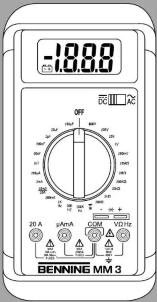
4. Tester description
refer to figure 1 front tester panel
The display and operating elements shown in figure 1 are denoted as follows:
① Digital display for measurement values, display for overrange indication,
② Polarity display,
③ Battery indicator, appears when the battery is low,
4 Selector switch for direct voltage (DC) or alternating voltage (AC),
5 Rotary switch for function and range selection
⑥ Terminals for capacitance measurements
⑦ Input terminal (positive ^1 ) for V, W and Hz,
8 COM-Terminal, common return terminal for current, voltage, resistance and frequency measurements, continuity and diode tests,
9 Input terminal (positive) for mA/mA range, for currents up to 200 mA,
10 Input terminal (positive) for 20 A range, for currents up to 20 A,
11 Protective rubber holster
1) the automatic polarity display for direct and alternating current refers to this terminal
5. General Specifications
5.1 General specifications for the BENNING MM 3
5.1.1 The digital display is a 312 digit liquid crystal display with 20 mm digit height and automatic decimal point placement. The highest display value is 1999.
5.1.2 The polarity display ② is automatic. As positive is implied by the defined input terminal, only a negative pole will be indicated with "-".
5.1.3 Overranging is indicated by "1" or "-1".
5.1.4 The measuring rate of the BENNING MM 3 is a nominal 2,5 readings per second rate.
5.1.5 The BENNING MM 3 is turned on and off using the rotary switch ⑤. Unit is turned off when switch is in "OFF" position.
5.1.6 The BENNING MM 3 powers off automatically after approx. 30 minutes. It can be powered on again by turning the rotary switch ⑤ to select another range.
5.1.7 Temperature coefficient of the measurement reading: 0.15 x (given accuracy)/ °C, < 18 °C or > 28 °C.
5.1.8 The BENNING MM 3 is powered by a 9 V block battery (IEC 6 LR 61).
5.1.9 When the battery voltage drops below the operating voltage of the BENNING MM 3 a low battery symbol appears in the display.
5.1.10 The lifespan of a battery is approx. 150 hours (Alkaline battery).
(L x W x H) = 175 x 84 x 31 mm without protective rubber holster (L x W x H) = 192 x 95 x 50 mm with protective rubber holster Meter weight: 340 g without protective rubber holster 550 g with protective rubber holster
5.1.12 The safety test leads provided with the meter are specifically suited for the rated voltage and current of the BENNING MM 3. The probe tips can be covered with protective caps.
5.1.13 The BENNING MM 3 is protected from mechanical damage by a protective rubber holster ⑪. The protective rubber holster ⑪ allows the BENNING MM 3 to be placed upright or hung up during measuring.
6. Ambient conditions
- The BENNING MM 3 is designed for measuring in dry conditions,
- Altitude during measuring: 2000 m maximum
- Overvoltage category/ Location category: IEC 60664-1/ IEC 61010-1 → 300 V category III, 600 V category II,
- Pollution degree : 2,
- Protection Class: IP 30 (DIN VDE 0470-1 IEC/ EN 60529)
IP 30 means: Protection against access to dangerous parts and protection against solid impurities of a diameter > 2.5 mm, (3 - first index). No protection against water, (0 - second index).
- Working temperature and relative humidity:
for working temperature between 0 °C and 30 °C : relative humidity smaller than 80 %
for working temperature between 30 °C and 40 °C : relative humidity smaller than 75 %
for working temperature between 40 °C and 50 °C : relative humidity smaller than 45 %
- Storage temperature: the BENNING MM 3 can be stored at temperatures between -20 °C and +60 °C. The battery should be removed when tester is in storage.
7. Electrical specifications
Note: measurement accuracy is given as the sum of
- a relative percentage of the reading and
- the number of least significant digits
This accuracy is valid for temperatures between 18 °C and 28 °C, with a relative
humidity smaller than 75 %.
7.1 Direct voltage ranges
The input impedance is 10 MΩ.
| Range | Resolution Accuracy | Overload protection |
| 200 mV | 100 μV ± (0,5 % of reading + 2 digits) 600 V | rms |
| 2 V | 1 mV ± (0,5 % of reading + 2 digits) 600 V | rms |
| 20 V | 10 mV ± (0,5 % of reading + 2 digits) 600 V | rms |
| 200 V | 100 mV ± (0,5 % of reading + 2 digits) 600 V | rms |
| 600 V | 1 V ± (0,5 % of reading + 2 digits) 600 V | rms |
7.2 Alternating voltage ranges
The input impedance is 10 MΩ parallel 100 pF. The measurement value is arrived at by average sensing and is displayed as the RMS value.
| Range | Resolution | Accuracy in 40 Hz - 500 Hz frequency range | Overload protection |
| 200 mV | 100 μV ± (1,3 % of reading + 5 digits) | 600 V | rms |
| 2 V | 1 mV ± (1,3 % of reading + 5 digits) | 600 V | rms |
| 20 V | 10 mV ± (1,3 % of reading + 5 digits) | 600 V | rms |
| 200 V | 100 mV ± (1,3 % of reading + 5 digits) | 600 V | rms |
| 600 V | 1 V ± (1,3 % of reading + 5 digits) | 600 V | rms |
7.3 Direct current ranges
Overload protection:
- 1 A (500 V) fast blow fuse on μA/ mA input terminal
- 16 A (500 V) fast blow fuse on 20 A input terminal
Current measurements in the 20 A range must last for 30 seconds maximum followed by a 3 minute break, 10 A continuous.
| Range | Resolution | Accuracy | Burden Voltage |
| 200 μA | 0,1 μA ± (1,0 % of reading + 2 digits) | 600 mV max. | |
| 2 mA | 1 μA | ± (1,0 % of reading + 2 digits) | 600 mV max. |
| 20 mA | 10 μA | ± (1,0 % of reading + 2 digits) | 600 mV max. |
| 200 mA | 100 μA ± (1,0 % of reading + 2 digits) | 900 mV max. | |
| 20 A | 10 mA | ± (2,0 % of reading + 3 digits) | 900 mV max. |
7.4 Alternating current ranges
The measurement value is arrived at by average sensing and is displayed as the RMS value.
Overload protection:
- 1 A (500 V) fast blow fuse on A/ mA input terminal
- 16 A (500 V) fast blow fuse on 20 A input terminal
Current measurements in the 20 A range must last for 30 seconds maximum followed by a 3 minute break, 10 A continuous.
| Range | Resolution | Accuracy in 40 Hz - 500 Hz frequency range | Burden Voltage |
| 200 μA | 0,1 μA | ± (1,5 % of reading + 3 digits) 600 mV | rms max. |
| 2 mA | 1 μA | ± (1,5 % of reading + 3 digits) 600 mV | rms max. |
| 20 mA | 10 μA | ± (1,5 % of reading + 3 digits) 600 mV | rms max. |
| 200 mA 100 μA | ± (1,5 % of reading + 3 digits) 900 mV | rms max. | |
| 20 A 10 mA | ± (2,5 % of reading + 5 digits) 900 mV | rms max. | |
7.5 Resistance ranges
Overload protection for resistance measurements: 600 V _rms .
| Range | Resolution | Accuracy | Maximum test current | Max. open circuit voltage |
| 200 Ω | 0,1 Ω ± (0.8 % of reading + 4 digits) | 2,5 mA 3,2 V | ||
| 2 kΩ | 1 Ω ± (0.8 % of reading + 2 digits) | 200 μA 0,5 V | ||
| 20 kΩ | 10 Ω ± (0.8 % of reading + 2 digits) | 40 μA 0,5 V | ||
| 200 kΩ | 100 Ω ± (0.8 % of reading + 2 digits) | 4 μA 0,5 V | ||
| 2 MΩ | 1 kΩ ± (0.8 % of reading + 2 digits) | 400 nA 0,5 V | ||
| 20 MΩ | 10 kΩ | ± (2 % of reading + 5 digits) | 40 nA | 0,5 V |
7.6 Diode and Continuity Testing
The accuracy indicated below is valid in the range of 0.4 V to 0.9 V.
Overload protection for diode testing: 600 V _rms .
The built-in buzzer sounds if the resistance R falls below 50 Ω.
| Range | Resolution | Accuracy | Maximum test current | Max. open circuit voltage |
| →+ >> | 1 mV | ± (1.5 % of reading + 5 digits) | 1,5 mA | 3,2 V |
7.7 Capacitance ranges
Conditions: Capacitors must be discharged before testing and then connected to the meter according to the indicated polarity.
| Range | Resolution | Accuracy | Frequency |
| 2 nF | 1 pF | ± (3.0 % of reading + 4 digits) | 40 Hz |
| 20 nF 10 pF | ± (3.0 % of reading + 4 digits) | 40 Hz | |
| 200 nF | 100 pF ± (3.0 % of reading + 4 digits) | 40 Hz | |
| 2 μF | 1 nF | ± (3.0 % of reading + 4 digits) | 40 Hz |
| 20 μF | 10 nF | ± (3.0 % of reading + 4 digits) | 40 Hz |
| 200 μF | 100 nF ± (3.0 % of reading + 4 digits) | 40 Hz | |
7.8 Frequency ranges
The frequency to be measured must have a minimum input signal of 200 mV_rms .
| Range | Resolution | Accuracy for 5 Vrms max. | Minimum input frequency | Overload protection |
| 2 kHz | 1 Hz | ± (1.5 % of reading + 5 digits) | 20 Hz | 600 Vrms |
| 20 kHz | 10 Hz | ± (1.5 % of reading + 5 digits) | 200 Hz | 600 Vrms |
| 200 kHz | 100 Hz | ± (1.5 % of reading + 5 digits) | 2 kHz | 600 Vrms |
8. Measuring with BENNING MM 3
8.1 Measurement preparation
The BENNING MM 3 must be used and stored only at the indicated storage and working temperatures, avoid exposure to continuous sunlight.
- Check the rated voltage and current indications on the test leads. The safety test leads provided with the BENNING MM 3 correspond specifically to the rated voltage and current of the BENNING MM 3.
- Inspect the test leads for damaged insulation. If the insulation is damaged, the test leads should be discarded immediately.
- Check test lead continuity. If the conductor in the test lead is damaged, the leads should be discarded immediately.
- Remove test leads from circuit to be measured before turning the rotary switch ⑤ to select another function.
- If the BENNING MM 3 is used near strong noise generating sources, the display may become unstable and measurement errors may arise.
8.2 Voltage and current measurement

To avoid electrical shock, observe the maximum rated voltage to earth ground!
The maximum rated voltage that should be applied between any of the following terminals of the BENNING MM 3 and earth ground is 600V .
- COM terminal 8
- Input terminal for V, Ω, and Hz ⑦
- Input terminal for μA/ mA range ⑨
- Input terminal for 20 A range ⑧

Electrical hazard! Maximum permissible circuit voltage for current measurement is 500 V! If a safety fuse blows at a voltage above 500 V the BENNING MM 3 could be damaged. A damaged tester presents an electrical shock hazard to the user!
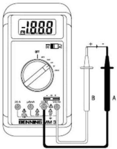
8.2.1 Voltage measurement
- Select the appropriate range with the rotary switch ⑤ of the BENNING MM 3.
- Use the selector switch ④ of the BENNING MM 3 to select the required direct (DC) or alternating (AC) voltage to be measured.
- Connect the black safety test lead to the COM-terminal 8 of the BENNING MM 3.
- Connect the red safety test lead to the input terminal for V, Ω, and Hz ⑦ of the BENNING MM 3.
- Connect the safety test leads to the circuit measurement points and read the measured value on the digital display ① of the BENNING MM 3.
see Figure 2: Direct voltage measurement
see Figure 3: Alternating voltage measurement
8.2.2 Current measurement
- Select the appropriate range with the rotary switch ⑤ of the BENNING MM 3.
- Use the selector switch ④ of the BENNING MM 3 to select the required direct (DC) or alternating (AC) current to be measured.
- Connect the black safety test lead to the COM-terminal 8 of the BENNING MM 3.
- Connect the red safety test lead to the input terminal for the A/ mA range ⑨ for currents up to 200 mA, or to the input terminal for the 20 A range ⑩ for currents between 200 mA and 20 A of the BENNING MM 3.
- Connect the safety test leads to the circuit measurement points and read the measured value on the digital display ① of the BENNING MM 3.
see Figure 4: DC current measurement
see Figure 5: AC current measurement
8.3 Resistance Measurement
- Select the appropriate range with the rotary switch ⑤ of the BENNING MM 3.
- Connect the black safety test lead to the COM-terminal 8 of the BENNING MM 3.
- Connect the red safety test lead to the input terminal for V, Ω, and Hz ⑦ of the BENNING MM 3.
- Connect the safety test leads to the circuit measurement points and read the measured value on the digital display ① of the BENNING MM 3.
see Figure 6: Resistance measurement
8.4 Diode Testing
- Turn the rotary switch 5 of the BENNING MM 3 to select the appropriate range identified by a buzzer and diode symbol (▶, ▶)
- Connect the black safety test lead to the COM-terminal 8 of the BENNING MM 3.
- Connect the red safety test lead to the input terminal for V, Ω, and Hz ⑦ of the BENNING MM 3.
- Connect the safety test leads across the diodes and read the measured value on the digital display ① of the BENNING MM 3.
- For a typical silicone diode tested in the forward-biased direction a voltage flow between 0,500 V and 0,900 V is displayed. A display showing "000" indicates a short circuit in the diode, whereas a display showing "1" indicates an open circuit in the diode.
- For a diode tested in the reverse-biased direction the display reads "1". If the diode is damaged, the display will show "000" or other values.
see Figure 7: Diode Testing
8.5 Continuity Testing with Buzzer
- Turn the rotary switch ⑤ of the BENNING MM 3 to select the appropriate range identified by a buzzer and diode symbol (▶).
- Connect the black safety test lead to the COM-terminal ⑧ of the BENNING MM 3.
- Connect the red safety test lead to the input terminal for V, Ω, and Hz ⑦ of the BENNING MM 3.
- Connect the safety test leads to the circuit to be measured. If the circuit resistance between the COM-terminal ⑧ and the input terminal for V, Ω and Hz ⑦ falls below 50 Ω, then the built-in buzzer in the BENNING MM 3 emits a continuous tone.
see Figure 8: Continuity Testing with buzzer
8.6 Capacitance Measurement

CAUTION! Capacitors must be completely discharged before attempting capacitance measurement! Never apply voltage to the input terminals for a capacitance measurement as this could destroy or damage the tester! A damaged tester may present an electrical shock hazard to the user!
- Use the rotary switch ⑤ to select the appropriate range on the BENNING MM 3.
- Establish the polarity of the capacitor and discharge the capacitor completely.
- Connect the fully discharged capacitor according to its polarity to the input terminals for capacitance measurement ⑥ of the BENNING MM 3 and read the measurement value on the digital display ① of the BENNING MM 3.
see Figure 9: Capacity Testing
8.7 Frequency measurement
- Use the rotary switch 5 to select the appropriate range on the BENNING MM 3.
- Connect the black safety test lead to the COM-terminal ⑧ of the BENNING MM 3.
- Connect the red safety test lead to the input terminal for V, Ω, and Hz ⑦ of the BENNING MM 3. Observe the voltage range of the BENNING MM 3 for frequency measurements!
- Connect the safety test leads to the circuit measurement points and read the measured value on the digital display ① of the BENNING MM 3.
see Figure 10: Frequency measurement
9. Maintenance

Remove test leads and turn the power off before opening the BENNING MM 3! Dangerous voltage!
Any work to be carried out on an opened BENNING MM 3 under voltage is strictly reserved for qualified electrotechnical personnel who must take special precautionary measures to avoid accidents.
This is how to ensure that the BENNING MM 3 is free from any voltage before the instrument is opened:
- first remove the safety test leads from measured object.
- then remove both safety test leads from the BENNING MM 3.
- turn the rotary switch ⑤ to the "OFF" position.
9.1 Instrument safe-guarding
In certain circumstances, safety during the use of the BENNING MM 3 can no longer be guaranteed; when for instance:
- there is visible damage to the housing
- measurement errors occur
- the instrument has been subjected to prolonged storage under unfavorable conditions and
- the instrument has been subjected to severe transport stresses.
In such cases the BENNING MM 3 must be immediately switched off, removed from the measurement points and secured against any future unintentional operation.
9.2 Cleaning
Wipe the case of the BENNING MM 3 with a clean dry cloth (exception: special cleaning cloths). Do not use any solvents and/or abrasives to clean the BENNING MM 3.
9.3 Battery replacement

Remove test leads and turn the power off before opening the BENNING MM 3! Dangerous voltage!
The BENNING MM 3 is powered by a 9 V block battery. Battery replacement (see figure 11 below) becomes necessary when the low battery indicator shows in the display ③.
This is how to change the battery:
- Remove the safety test leads from the measured circuit.
- Remove the safety test leads from the BENNING MM 3.
- Turn the rotary switch ⑤ to the "OFF" position.
- Remove the protective rubber holster ⑪ from the BENNING MM 3.
- Place the BENNING MM 3 on its front side and remove the three screws from the case back.
- Lift the end of the case back near the input terminals until it gently unsnaps from the case front at the end nearest to the LCD display ①.
- Remove the empty battery from inside the case front and carefully disconnect it from the battery connector leads.
- Snap the battery connector leads to the terminals of a new battery and reinsert the battery into the case front. Ensure that the battery leads do not become pinched between the case back and case front.
- Press the case back and case front together again and reinstall the three screws.
- Place the BENNING MM 3 back into its protective rubber holster ⑪.
see Figure 11: Battery replacement

Please contribute to environmental protection! Batteries should not be thrown into domestic refuse bins! They can be discarded at collection points for old batteries or special refuse. Please contact your municipality for more information.
9.4 Fuse replacement

Remove test leads and turn the power off before opening the BENNING MM 3! Dangerous voltage!
The BENNING MM 3 is protected from overloading by a built-in 1 A (G-cartridge) fast blow fuse and a built-in 16 A (G-cartridge) fast blow fuse (see figure 12).
This is how to replace the fuses:
- Remove the safety test leads from the measured circuit.
- Remove the safety test leads from the BENNING MM 3.
- Turn the rotary switch ⑤ to the "OFF" position.
- Remove the protective rubber holster ⑪ from the BENNING MM 3.
- Place the BENNING MM 3 on its front side and remove the three screws from the case back.
- Lift the end of the case back near the input terminals until it gently unsnaps from the case front at the end nearest to the LCD display ①.

Do not remove any screws from the printed circuit board of the BENNING MM 3!
- Lift the printed circuit board from the front case.
- Gently pry one end of the defective fuse loose from the fuse holder.
- Then slide the defective fuse completely out of the fuse holder.
- Install a new fuse of the same rating, fast acting characteristic and size.
- Make sure the new fuse is centered in the fuse holder.
- Replace the printed circuit board into the case front.
- Ensure that the battery leads do not become pinched between the case back and case front.
- Press the case back and case front together again and reinstall the three screws.
- Place the BENNING MM 3 back into its protective rubber holster ⑪ again. see Figure 12: Fuse replacement
9.5 Calibration
Benning guarantees compliance with the technical and accuracy specifications stated in the operating manual for the first 12 months after the delivery date.
To maintain the specified accuracy of the measurement results, the instrument must be recalibrated at regular intervals by our factory service. We recommend a recalibration interval of one year. Send the appliance to the following address:
Fuse F 16 Å, 500 V, D = 6.35 mm, L = 32 mm, part no. 749770
Fuse F 1 A, 500 V, D = 6.35 mm, L = 32 mm, part no. 749669
10. How to use the protective rubber holster
- The safety test leads can be stored by wrapping them around the protective rubber holster ⑪ and then clipping the probes into the protective probe holders on the rear of the holster ⑪ (see figure 13).
- A safety test lead can be clipped into the probe holder on the protective rubber holster ⑪ with the test probe protruding, in order to apply the probe together with the BENNING MM 3 to a measuring point.
- The rear tilt stand on the protective rubber holster ⑪ allows the BENNING MM 3 to be placed standing upright (for easier display reading) or hung up (see figure 14).
- The protective rubber holster ⑪ can also be hung on a nail if so desired.
see Figure 13: Winding up the safety test leads
see Figure 14: Erecting the BENNING MM 3
11. Technical data of the measuring accessories
- Standard: EN 61010-031,
- Maximum rated voltage to earth ( ± ) and measuring category:
With push-on caps: 1000 V CAT III, 600 V CAT IV,
Without push-on caps: 1000 V CAT II, - Maximum rated current: 10 A,
- Protective class II (回), continuous double or reinforced insulation,
- Contamination class: 2,
- Length: 1.4 m, AWG 18,
-Environmentalconditions:
Maximum barometric elevation for making measurements: 2000 m,
Temperatures: 0 °C to + 50 °C, humidity 50 % to 80 %
- Only use the measuring leads if in perfect and clean condition as well as according to this manual, since the protection provided could otherwise be impaired.
- Throw the measuring lead out if the insulation is damaged or if there is a break in the lead/ plug.
- Do not touch the bare contact tips of the measuring lead. Only grab the area appropriate for hands!
- Insert the angled terminals in the testing or measuring device.
12. Environmentalnote

At the end of the product's useful life, please dispose of the device at collection points provided in your community.