
GECH 3665 Li - Hedge Trimmers EINHELL - Free user manual and instructions
Find the device manual for free GECH 3665 Li EINHELL in PDF.
| Product type | Robot mower |
| Brand | Einhell |
| Model | GECH 3665 Li |
| Rated voltage | 18 V |
| Battery type | Power-X-Change (Li-Ion) |
| Cutting width | 18 cm |
| Cutting height adjustment | 20 - 60 mm, continuous |
| Number of blades | 3 |
| Maximum slope | 25 % |
| Weight | 8.75 kg |
| Protection rating | IPX4 |
| Sound pressure level | 46 dB(A) |
| Sound power level | 57 dB(A) |
| Motor rotation speed | 3400 rpm |
| Station power supply | 100-240 V ~50/60 Hz, output 24 V DC, 1.5 A |
| Protection class | III |
| Main functions | Automatic random mowing, boundary detection via camera and sensors, automatic return to charging station, timer scheduling, rain detection. |
| Safety | Main switch, PIN code, lift sensor, tilt sensor, obstacle sensor, automatic stop. |
| Maintenance | Regular cleaning, replacement of blades (3 blades simultaneously), software update via USB. |
| Spare parts | Replacement blades ref. 34.140.20 |
| Warranty | 24 months (current conditions) |
| Delivery contents | Robot mower, charging station, power supply unit, guide cable, replacement blades, magnetic strip, hex key, fixing screws, instruction manual. |
Frequently Asked Questions - GECH 3665 Li EINHELL
User questions about GECH 3665 Li EINHELL
0 question about this device. Answer the ones you know or ask your own.
Ask a new question about this device
Download the instructions for your Hedge Trimmers in PDF format for free! Find your manual GECH 3665 Li - EINHELL and take your electronic device back in hand. On this page are published all the documents necessary for the use of your device. GECH 3665 Li by EINHELL.
USER MANUAL GECH 3665 Li EINHELL
GB Original operating instructions Robot lawn mower
natural_image
Technical line drawing of a mechanical component with no visible text or symbols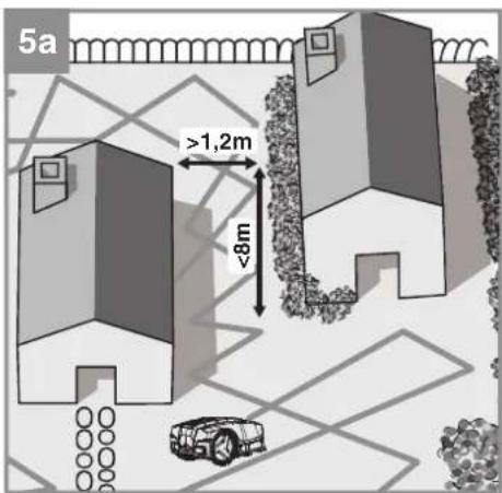
natural_image
Silhouettes of a family with a stroller and a small robot, no text or symbols present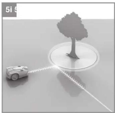
natural_image
3D rendering of a small robot with light trail path interacting with a tree on a reflective surface (no text or symbols)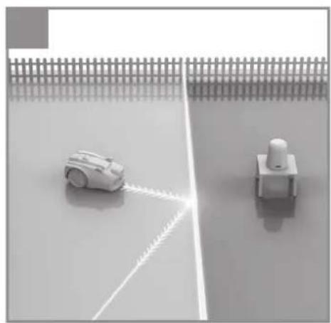
natural_image
Two robotic devices on a tiled floor, one with a white arm and the other with a white push-button switch (no text or symbols visible)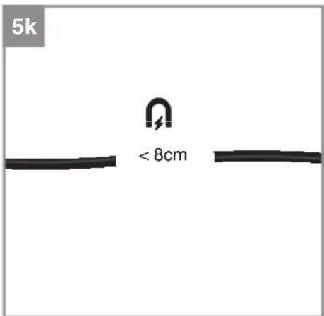
flowchart
graph TD
    A["Top Vehicle"] --> B["Left Side"]
    B --> C["Right Side"]
    C --> D["Check Icon with Alert Signal"]
    D --> E["Bottom Vehicle"]
    E --> F["Left Side"]
    F --> G["Right Side"]
    G --> H["Check Icon with Alert Signal"]
    H --> I["Right Side"]
    I --> J["Check Icon with Alert Signal"]
    J --> K["Right Side"]
    K --> L["Check Icon with Alert Signal"]
    L --> M["Right Side"]
    M --> N["Check Icon with Alert Signal"]
    N --> O["Right Side"]
    O --> P["Check Icon with Alert Signal"]
    P --> Q["Right Side"]
    Q --> R["Check Icon with Alert Signal"]
    R --> S["Right Side"]
    S --> T["Check Icon with Alert Signal"]
    T --> U["Right Side"]
    U --> V["Check Icon with Alert Signal"]
    V --> W["Right Side"]
    W --> X["Check Icon with Alert Signal"]
    X --> Y["Right Side"]
    Y --> Z["Check Icon with Alert Signal"]
-7-
natural_image
Line drawing of a car dashboard with steering wheel and rearview (no text or symbols)13
A
B
C
D
E

[Non-Text]

G
H

1
D
Inhaltsverzeichnis
- Safety Information
-
Layout and items supplied
-
Intended use
-
Technical data
-
Starting up
-
Operation
-
Cleaning, maintenance and ordering spare parts
-
Storage
-
Transport
-
Disposal and recycling
-
Charging station display and troubleshooting
-
Robot lawn mower display and troubleshooting
-
FREELEXO CAM data protection notice
-
Charger indicator

Danger! - Read the operating instructions to reduce the risk of injury.
Children are not allowed to use this equipment. This equipment can be used by people with limited physical, sensory or mental capacities or those with no experience and knowledge if they are supervised or have received instruction in how to use the equipment safely and understand the dangers which result from such use. Children are not allowed to play with the equipment.
Children are not allowed to clean the equipment or carry out user-level maintenance work.
GB
Danger!
When using this equipment, a number of safety precautions must be observed to avoid injuries and damage. Please read the complete operating instructions and safety information with due care. Keep these operating instructions in a safe place so that the information is available at all times. If you give the equipment to any other person, hand over these operating instructions and the safety information as well. We cannot accept any liability for damage or accidents which arise due to failure to follow these instructions and the safety information.
1. Safety Information
For the relevant safety information please refer to the booklet included in delivery.
Warning!
Read all the safety information, instructions, illustrations and technical data provided on or with this power tool. Failure to adhere to the following instructions may result in electric shock, fi re and/or serious injury.
Keep all the safety information and instructions in a safe place for future use.
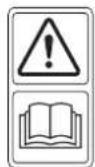
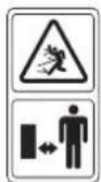
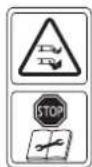
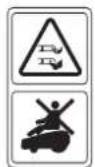
Explanation of the symbols used (see Fig. 13)
A. WARNING - Read the operating instructions before you start using the machine!
B. WARNING - Keep a safe distance away from the machine when it is in operation!
C. WARNING - Always actuate the locking mechanism before carrying out any work on the machine or before lifting the machine! CAUTION - Do not touch rotating blades!
D. WARNING - Do not ride on the machine!
CAUTION - Do not touch rotating blades!
E. Protection class II (double-insulated).
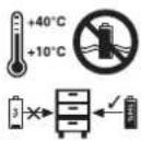
F. Store the battery only in dry rooms with an ambient temperature of +10°C to +40°C. Place only charged batteries in storage (charged at least 40%).
G. Protection class III
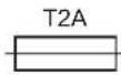
H. Slow fuse 2 A
I. For use in dry rooms only.
J. WARNING: To charge the battery, use only the removable power supply unit NT24/1 / PS24/ 1 delivered with this tool.
Important!
Pull out the power plug and disconnect the guide cable from the charging station during a thunder storm.
2. Layout and items supplied
2.1 Layout (Fig. 1/2)
- Robot lawn mower
- Control panel
- "STOP" button / release button for the control panel cover
- Cutting height adjustment facility
- Rain sensor
- Carry-handle
- Main switch
- Rear wheel
-
Battery compartment cover
-
Blades
- Blade plate
- Front wheel
- Control panel cover
-
USB connection
-
Camera unit
-
Distance sensors
-
Charging station
19a. Charging station LED display
19b. Charging station charging pin
-
Power supply unit (cable)
-
Fastening screw
-
Hexagon key
-
Fastening peg
-
Guide cable
-
Cable connector
-
Spare blades
-
Magnetic tape
-
Ruler (for detaching)
2.2 Items supplied and unpacking
Please check that the article is complete as specified in the scope of delivery. If parts are missing, please contact our service center or the store where you made your purchase at the latest within 5 work days after purchasing the article and upon presentation of a valid bill of purchase. Also, refer to the warranty table in the service information at the end of the operating instructions.
- Open the packaging and take out the equipment with care.
- Remove the packaging material and any packaging and/or transportation braces (if present).
- Check to see if all the items are present.
- Inspect the grass trimmer and accessories for transport damage.
- If possible, keep the packaging until the end of the guarantee period.
GB
Danger!
The equipment and packaging material are not toys. Do not let children play with plastic bags, foils or small parts. There is a risk of choking and suffocating!
Scope of delivery, assembly material and accessories (some not included):
Details of the scope of delivery can be found in the enclosed related information sheet.
- Robot lawn mower
• Power supply unit (cable) - Chargingstation
• Fastening screws (4 pcs) - Spareblades
- Fasteningpegs
- Guidecable
Cableconnector - Magnetictape
- Hexagonkey
- Battery
• Ruler (for detaching)
• Original Operating Instructions
• SafetyInformation
Required aids (not supplied)
- Hammer
• Pair of pliers - Wirestripper
• Spirit level (optional)
3. Intended use
The robot lawn mower is intended for private use, i.e. for use in home and garden environments and only for mowing lawns.
The equipment is allowed to be used only for its prescribed purpose. Any other use is deemed to be a case of misuse. The user/operator and not the manufacturer will be liable for any damage or injuries of any kind resulting from such misuse.
Please note that our equipment has not been designed for use in commercial, trade or industrial applications. Our warranty will be voided if the equipment is used in commercial, trade or industrial businesses or for equivalent purposes.
4. Technical data
Voltage 18 V
Motor speed 3400 min ^1
Protection IPX4
Protection class ....III
Weight 8.75 kg
Cutting width 18 cm
Number of blades 3
Max. gradient 25%
Sound pressure level L_pA 46 dB(A)
Uncertainty K 2.3 dB
Sound power level L_w .....57dB(A)
Uncertainty K 2.3 dB
Cutting height adjustment .... 20-60 mm; infi nitely adjustable
Guide cable antenna
Operating frequency band: 0-148.5 KHz
Maximum transmission power: .....67.05 dBuA/m
Power supply unit
Input voltage: 100-240 V \~ 50/60 Hz
Output voltage: 24 V DC
Output current: 1.5 A
Protection class: ....II /回
Sound values were measured in accordance with the standards EN ISO 3744:1995 and ISO 11094:1991.
Warning!
This equipment generates an electromagnetic fi eld during operation. Under certain circumstances this fi eld might actively or passively impede medical implants. To reduce the risk of serious or fatal injuries, we recommend persons with medical implants to consult their doctor and the manufacturer of the medical implant prior to using the equipment.
5. Starting up
Read the operating instructions fully before you start work on the installation of the robot lawn mower. The quality of the installation work has a direct effect on the mowing results.
GB
5.1 How it works
Follow the operating instructions carefully in order to ensure that the robot lawn mower works correctly and safely.
The robot lawn mower chooses its direction on a random basis. The entire garden gets mowed by the robot lawn mower reaching all areas that are not blocked off by boundaries and obstacles. When the robot lawn mower discovers that it has reached a lawn boundary or recognizes an obstacle, it will change its direction and mow in a different random direction. Using sensors the robot lawn mower can distinguish between obstacles and lawn areas, enabling it to move freely within its work area.
The robot lawn mower has a camera unit which generates and processes images of the area lying ahead. On this basis the area lying ahead is examined as to whether it is an area for mowing or a lawn boundary or an obstacle. If the area lying ahead is assessed as being an area for mowing, the robot lawn mower will move straight ahead with the mower unit activated. If the area lying ahead is assessed as being a lawn boundary or an obstacle, the robot lawn mower will stop, check again for an area for mowing and continue mowing in a random direction. The area for mowing must be checked and adapted carefully so that the robot lawn mower has enough room to recognize where it ends. The lawn boundaries must be clearly defined so that the robot lawn mower can recognize them within its reaction time.
The purpose of the laid guide cable (24) is to get the robot lawn mower to dock punctually in the charging station (19); it does not set any limits during mowing. It is imperative therefore for the robot lawn mower to be on a lawn area with clear optical or physical limits. For the robot lawn mower to find the guide cable (24) and subsequently the charging station (19) it must be in the charging station (19) when mowing mode is started for the first time. It uses a global navigation satellite system (GNSS) to determine the position of the charging station (19). If the position of the charging station (19) is ever changed, it is essential for the robot lawn mower to be placed again in the charging station (19) for calibration. Make sure that there is no shielding or roofing which could prevent the positioning operation. Avoid placing the charging station (19) near high buildings. Under some circumstances calibration might fail in such cases due to a poor signal.
When the battery charge level is low, the robot lawn mower will return to the charging station (19). With the help of the GNSS module the robot lawn mower will determine its distance from the charging stations (19) and look for it. If the robot lawn mower comes up against a garden boundary or any obstacles on its way to the search loop, it will save its position and the mowing area will be mapped. This will help the robot lawn mower to return to the charging station (19) faster in future use. When the robot lawn mower arrives at the guide cable (24) it will return to the charging station (19) using its wire recognition sensors. This can take several minutes depending on the garden's size and complexity.
The global navigation satellite system (GNSS) is also used to acquire location-specific sunrise and sunset data. There must be sufficient daylight for the robot lawn mower to work properly. Check the lens of the camera unit (15) regularly for signs of dirt.
5.2 Sensors
The robot lawn mower is equipped with a number of safety sensors. These sensors enable the robot lawn mower to move within its mowing area.
• Lifting sensor:
If the robot lawn mower is raised at the back by more than 30^ from the ground or if a front wheel (12) loses contact with the ground, the robot lawn mower and the rotation of the blades (10) will be stopped immediately.
- Tilting sensor:
If the robot lawn mower tilts severely in any direction, the robot lawn mower and the rotation of the blades (10) will be stopped immediately.
- Obstacle sensor:
The robot lawn mower is able to detect obstacles in its path. If the robot lawn mower collides with an obstacle, the robot lawn mower and the rotation of the blades (10) will be stopped immediately and the mower will reverse away from the obstacle.
- Camera unit:
The robot lawn mower comes with a camera unit (15) which analyzes the mowing area (approx. 1m^2 ) lying ahead of it. The camera is directed at the ground so that the objects lying in the screen area appear with a maximum height of 50 cm. The image material to be processed is saved only locally and temporarily on the robot lawn mower and is continually overwritten. The robot lawn mower
GB
can recognize obstacles and the work area in which there is no longer any lawn. When the robot lawn mower comes across an obstacle or no longer detects any lawn, it will stop and begin to mow again in a random direction. Because of the camera unit it is impossible for the robot lawn mower to work in twilight or during the night. The selected work window should lie within daytime hours when there is enough daylight for the robot lawn mower to work reliably. This also helps to protect semi-nocturnal animals such as hedgehogs.
• Distance sensors:
The robot lawn mower is equipped with distance sensors (16) which enable it to detect obstacles along its path. When the robot lawn mower comes across an obstacle, it will stop and begin to mow again in a random direction.
• Magnetic tape sensor:
The robot lawn mower is equipped with a magnetic tape sensor for recognizing a magnetic tape (27) lying on the ground. When the robot lawn mower comes across a magnetic tape it will stop and begin to mow again in a random direction. The magnetic tape serves as a virtual boundary for creating areas of the garden where the robot lawn mower is not allowed to mow.
- Rain sensor:
The robot lawn mower is equipped with a rain sensor (5) to prevent it from operating in the rain. When the robot lawn mower detects rain it will return to the charging station (19) and and be completely recharged there. When the rain sensor (5) is dry again, the robot lawn mower will begin working again provided it is still in an active time window. When the rain sensor (5) is triggered, the rain sensor LED (53) will light up. Do not short-circuit the two metal sensors with metal or any other conductive material. This will impede the correct operation of the robot lawn mower.
• GNSS module:
The robot lawn mower determines its position and the position of the charging station (19) by means of a global navigation satellite system (GNSS). This helps the robot lawn mower to find its way back to the charging station (19). The robot lawn mower can use the GNSS module to determine the local times for sunrise and sunset so that it is prevented from mowing in twilight and during the night. This also means that the robot lawn mower can work reliably with its camera unit (15).
The robot lawn mower also uses the GNSS module at all times to determine its distance from the charging station (19). The robot lawn mower is allowed to move no more than 1000 m from the charging station (19) or else the GNSS LED (54) will turn yellow and the robot lawn mower cannot be operated in Main Area mode. The mower's distance from the charging station (19) is irrelevant for operation in Secondary Area mode.
5.3 Preparations
If the grass is taller than 60 mm it has to be shortened first to avoid exposing the robot lawn mower to excessive load and adversely affecting its operating efficiency. Use a conventional lawn mower or trimmer to do this. Remove all loose objects from the lawn which could get damaged by the robot lawn mower or cause damage to the robot lawn mower itself.
Check the mowing area, the lawn boundary and any areas that you don't want to be mowed. The following sections of these operating instructions contain information about how you can defi ne precise lawn boundaries and protect specifi c are-as. Some obstacles can be detected by the robot lawn mower in good time and require no elaborate protection.
Have the following tools ready: A hammer, tongs, a wire stripper and a spirit level (optional).
5.3.1 Calculating the gradient of the lawn
The robot lawn mower can cope with gradients of up to 25%. You therefore need to avoid steeper gradients. The gradient can be determined on the basis of height divided by distance (Fig. 3a).
$$ \text { Example: } a / b = 25 \mathrm{cm} / 100 \mathrm{cm} = 25 \% $$
5.3.2 Installing the battery
A battery (A) from the Power-X-Change series is needed to operate the robot lawn mower. Important: Depending on the model of your robot lawn mower, it might not come complete with the battery (A). Open the battery compartment cover (9). Press the pushlock button of the battery (A) and push the battery (A) into the mount provided. Close the battery compartment cover (9) and make sure that it latches in place correctly (Fig. 3b). To remove the battery (A), open the battery cover (9). Press the pushlock button of the battery (A) and pull out the battery (A).
GB
5.4 Charging station
5.4.1 Position of the charging station
Begin by determining the best position for the charging station (19). You need an outdoor socket outlet with a permanent supply of electricity so that the robot lawn mower works at all times. The charging station (19) must be placed on a fl at area on level with the turf. Make sure that the area is fl at and dry. Ideally you should position the charging station (19) at the edge of the mowing area. Please note that the power cable for the charging station (19) should not be laid inside the mowing area. If it is, it will need to be buried to avoid it being damaged by the robot lawn mower. Position the charging station (19) together with the guide cable (24) on an open area free of obstacles which is as accessible as possible from all directions. Avoid positioning the charging station (19) in hard-to-reach corners or in areas that can be reached only through bottlenecks.
The maximum distance from the charging station (19) to a lawn boundary is not allowed to exceed 1000 m. This serves to reduce the risk of theft. At greater distances the GNSS LED (54) will turn yellow and the robot lawn mower cannot be operated in Main Area mode. The mower's distance from the charging station (19) is irrelevant for operation in Secondary Area mode. To guarantee efficient and automatic mowing it is recommended to restrict the distance from the lawn boundary to the charging station (19) to 50 m. As the distance from the charging station (19) increases, it is possible that the robot lawn mower will no longer have enough battery power for it to return to the charging station (19). Use a battery with greater capacity for larger mowing areas.
Select a position in the shade because it is best to charge the battery in cool surroundings. Tall buildings or trees can weaken the GNSS signal so that the robot lawn mower is no longer able to find its way back to the charging station (19) automatically. It is important therefore to keep a reasonable distance away from tall buildings and trees and to make sure that the charging station (19) lies under the open sky. Also note that the guide cable (24) must be laid in a straight line for least 1 m in front of the charging station (19) and for at least 0.5 m behind the charging station (19) (Fig. 4a). Curves immediately in front of the charging station (19) could cause problems when docking for charging.
5.4.2 Localization of the charging station
When the battery is almost empty, the robot lawn mower will return to the charging station (19) by
following the guide cable (24). The robot lawn mower compares its actual position with the calibrated position of the charging station in regular intervals with the help of GNSS. The robot lawn mower travels in the direction of the charging station (19) and looks for the guide cable (24) in several steps. As it does so, the robot lawn mower stops now and again before setting off if necessary in a different direction in order to reach the guide cable (24). When the robot lawn mower gets near to the guide cable (24) it will begin to detect its position with the help of rotary movements and the strength of the signal transmitted by the guide cable (24).
If the robot lawn mower comes across an obstacle or a lawn boundary while mowing, this position will be saved. The map produced as the result helps the robot lawn mower to find the charging station (19) more quickly.
When the robot lawn mower reaches the guide cable (24) it will follow it counter-clockwise to the charging station (19). Make sure, therefore, that the charging station (19) faces in the right direction when you position it (Fig. 4a).
5.4.3 Connecting the charging station to the power supply unit
-
Before you connect the charging station (19) to the power supply, check that the mains power supply is 100-240 V at 50/60 Hz.
-
Connect the power supply unit (20) directly to a socket outlet. Do not use the cable for any other use.
-
Do not use the power supply unit if it is damaged (20). In the event of any damage to cables or the power supply unit (20), contact an authorized professional immediately for replacement.
-
Do not charge the robot lawn mower in a damp location. Do not charge the robot lawn mower at temperatures above 40^ C or below 5^ C.
-
Keep the robot lawn mower and the power supply unit (20) away from water, sources of heat and chemicals. Keep the cable of the power supply unit (20) away from sharp edges in order to prevent damage.
-
Connect the power supply unit (20) to the charging station (19) (Fig. 4b).
-
With the main switch (7) set to ON and with a battery inserted, place the robot lawn mower in the charging station (19) and charge it fully before you use it for the first time.
GB
5.4.4 Information about charging
The robot lawn mower will return to the charging station (19) in each of the following situations:
- You send the robot lawn mower back manually.
• The battery charge level drops below 30%. - The end of the daily work time has been reached.
• The rain sensor has tripped.
• The robot lawn mower has become overheated. - When twilight falls, making it impossible for the camera unit to work correctly.
In this case the robot lawn mower looks for the guide cable (24) and then travels automatically clockwise along the guide cable (24) as far as the charging station (19).
While the battery is being charged, the battery LED (55) of the robot lawn mower will flash green. When the battery is fully charged, the battery LED (55) and the LED display (19a) at the charging station (19) will light up green. Once it has been fully charged, the robot lawn mower will resume operation or remain in the charging station (19) until the next work time window.
If there is an obstacle on the guide cable (24) during the trip back to the charging station (19), the robot lawn mower will come to a stop in front of the obstacle after several attempts and will not be able to get back to the charging station (19). Remove all obstacles on the guide cable (24). If the temperature of the battery exceeds 45 ^ , charging will stop in order to prevent damage to the battery. Charging will resume automatically once the temperature has dropped again.
If the temperature of the robot lawn mower controller exceeds 65 ^ , the robot lawn mower will return to the charging station (19). Operation will resume in accordance with the settings once the temperature has dropped again. If the battery becomes empty before the robot lawn mower has returned to the charging station (19), the robot lawn mower will be unable to start up again. Bring the robot lawn mower back to the charging station (19) and leave the main switch (7) switched on. The robot lawn mower will be charged up automatically.
5.5 Guide cable
IMPORTANT! A severed guide cable and any consequential damages are not covered by the warranty!
5.5.1 Laying the guide cable
The guide cable (24) can be laid both on the ground and in the ground. The fastening pegs (23) might break while they are being hammered into hard or dry ground. If the ground is very dry, water the lawn before installing the guide cable (24).
• Installation on the ground
Lay the guide cable (24) securely on the ground and fasten it with the supplied fastening pegs (23). You can adjust the position of the guide cable (24) during the first weeks of using the robot lawn mower. In the course of time, however, the guide cable will become overgrown with grass and will be no longer visible. Install the guide cable (24) with a maximum distance of 1 m between the fastening pegs (23). Avoid situations in which the guide cable (24) is not actually lying on the ground. Make sure that the guide cable (24) cannot be severed by the robot lawn mower. While the robot lawn mower is mowing, it will travel with its activated mower unit over the guide cable.
• Installation in the ground
Bury the guide cable (24) in the ground at a depth of up to 5 cm. This will prevent damage to the guide cable (24) during for example scarifying or aeration.
Important!
Because the guide cable (24) is not always laid along the lawn boundary, it is important to make a note of where the guide cable (24) is positioned so that it is not damaged during future garden projects. Make a drawing or take photos to document the arrangement. If the guide cable (24) is not buried in the ground you should not scarify or aerate near the guide cable (24) so as to avoid damaging it.
5.5.2 Installing the search loop
- The guide cable (24) forms a search loop which is used by the robot lawn mower to find its way back to the charging station (19).
- Lay the guide cable (24) in a straight line for least 1 m in front of the charging station (19) and for at least 0.5 m behind the charging station (19) (Fig. 4a). Curves immediately in front of the charging station (19) could cause problems when docking for charging.
- The guide cable (24) should enclose a minimum area of 5m^2 (Fig. 4a). It is recommended to use the entire length of the guide cable (24) and to lay it in the shape of a square as far as possible. The search loop should be orientated so that the robot lawn mower is well
GB
able to get to the charging station (19) from any point in the garden.
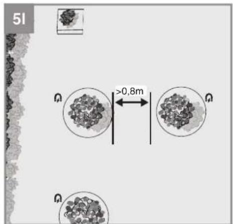
• The distance between two guide cables (24) should amount to at least 0.8 m (Fig. 4a).
- The guide cable (24) is not allowed to cross over itself.
- Make sure there are no obstacles on the guide cable (24).
- Make sure there are no obstacles within a distance of approx. 30 cm to the left and right of the guide cable (24) (Fig. 4c). Keep away from the garden boundary and from overly high paving stones. If the path runs at ground level with the lawn you can lay the guide cable (24) there without leaving a gap.
5.6 Connecting the charging station
Finish laying the complete guide cable (24) before you connect it to the charging station (19). Use a wire stripper to remove a length of 10 to 15 mm of the insulation from the ends of the guide cable (24) for connecting to the charging station (19).
Pull out the power plug before you connect the guide cable (24) to the charging station (19). The end of the guide cable (24) laid to the front side of the charging station (19) must be run to the back via the cable holders on the underside of the charging station (19). Check that this end is fastened securely to the charging station (19) and is connected to the left black connector.
After the guide cable (24) has been laid, pass the free end through the hole and connect it to the red connection on the right (Fig. 4d).
Important! The guide cable (24) is not allowed to cross over itself!
Then connect the power supply. When the installation is completed correctly, the LED display (19a) on the charging station (19) should light up green permanently. If the LED does not light up, check the connections fi rst.
If the LED lights up green but not permanently, read the table entitled "Display on the charging station and troubleshooting" at the end of these operating instructions.
5.7 Mowing area - Obstacles and mowing area boundaries
5.7.1 Lawn boundary
The mowing area must have a precise and fully enclosing lawn boundary. Familiarize yourself with
the possibilities for defi ning a lawn boundary as described in this section. Then start at any point of the lawn boundary with an examination of the garden boundary and follow the boundary in a circle until you arrive back at your starting point. Any sections of the work area that you want to exclude must be enclosed likewise with a precise lawn boundary. Proceed in the same way as for the outer boundaries of the mowing area.
- Bottlenecks
If the lawn area has a bottleneck, your robot lawn mower will be able to operate there as long as the corridor has a width of at least 1.2 m and a maximum length of 8 m (Fig. 5a). In the case of long and narrow bottlenecks, the robot lawn mower might no longer be able to find its way back to the charging station (19).
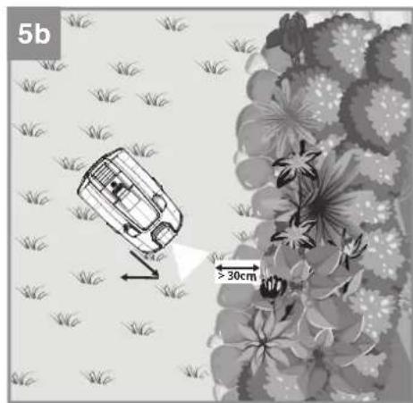
• Distance from the lawn boundary
When the robot lawn mower approaches the lawn boundary, this will be detected by the camera unit (15) at the front of the robot lawn mower. The lawn-free distance should amount to at least 30 cm (Fig. 5b). Check that there is no difference in height at the lawn boundary as the robot lawn mower might travel beyond the exact lawn boundary before it stops and sets off again in a different direction. Deeper lying garden beds or elevated paving edges might result in damage to the robot lawn mower. Check the lawn boundaries regularly because if they become overgrown this could result in the robot lawn mower leaving the mowing area. It is also possible for the lawn boundary to be edged in with fl at path stones to create a clear separation from the mowing area.
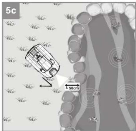
• Lawn boundary with water
As a general rule the robot lawn mower will reliably recognize the lawn boundary as described above. However, given the possibility that the robot lawn mower will overrun the lawn boundary we recommend a gap of approx. 50 cm between the lawn boundary and any water feature (a pond, pool, etc.) (Fig. 5c). Alternatively we recommend isolating the water feature with a raised all-round edge in order to protect the robot lawn mower more reliably.
- Lawn boundary with a raised edge higher than 25 cm
The robot lawn mower can use the distance sensors (16) to recognize obstacles with a minimum height of 25 cm (Fig. 5d). You can also use high obstacles to demarcate your lawn boundary. The robot lawn mower will stop at a distance of approx. 20 cm in front of the
GB
obstacle and turn so that it can continue mowing in another direction. Important! - This means that the robot lawn mower does not mow as far as the lawn boundary but leaves an area of approx. 20 cm unmowed.
- Lawn boundary with a raised edge higher than 10 cm
The robot lawn mower can use the collision sensors to collide with obstacles below 25 cm. This function can also be used to define a lawn boundary. In this case make sure that the edging is sturdy and at least 10 cm high (Fig. 5e).
5.7.2 Obstacles
Obstacles are objects situated in the mowing area. The robot lawn mower can recognize many obstacles by means of the sensors. Soft, unstable and valuable objects must be protected where necessary. See the possibilities described above for separation from the lawn boundary.
- Obstacles with a height over 25 cm (Fig. 5f)
Solid obstacles which are over 25 cm in height and have a minimum width of 3 cm, e.g. trees, walls, fences, garden furniture, etc., are detected by the distance sensors (16). If the robot lawn mower comes up against an obstacle, it will stop and continue mowing in a different direction. In this case the area stretching approx. 20 cm to the obstacle will not be mowed.
- Obstacles with a height under 25 cm (Fig. 5g)
If an obstacle is not recognized by the distance sensors (16), the robot lawn mower will collide with the obstacle and trigger the collision sensors. The robot lawn mower will stop and continue mowing in a different direction. The obstacles must have a height of at least 10 cm. Protect sensitive and unstable objects with all-round edging.
- Stones and low obstacles under 10 cm Stones, rocks and low obstacles of less than 10 cm in the mowing area need to be protected because otherwise the robot lawn mower could run over them. If not, this could result in the robot lawn mower getting damaged or blocked. (See the section "Lawn boundary"). The robot lawn mower treats trees as obstacles. However, where any tree roots project above the ground to a height of less than 10 cm, the area in which they are located needs to be protected. This will prevent damage to the roots and to the robot lawn mower.
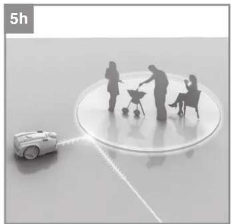
5.7.3 Magnetic tape (Fig. 5h-j)
Obstacles such as fences and hedges which poorly reflect the distance signal transmitted by the robot lawn mower are not detected in part or only very late. Obstacles with a weak optical contrast relative to the mowing areas can also be difficult to recognize. Such areas can be protected by magnetic tape (27) as a safe and contact-free means of getting the robot lawn mower to change its direction.
The magnetic tape (27) serves as a mobile and temporary boundary in the mowing area. The magnet sensors installed in the robot lawn mower detect the magnetic tape (27) and turn away at its limits. In this way you can separate off parts of the garden which are off limits, for example:
- Short-term separation of a part of the garden for a garden party where the robot lawn mower is not allowed to enter.
- Placement of a trampoline or swimming-pool in the mowing area over the summer months.
- A recently planted tree is still very sensitive and is best protected at an early stage from collisions with the robot lawn mower.
- A seasonal flower meadow is planned to attract insects. This area is off-limits for the robot lawn mower and needs to be protected from the outset.
- A new lawn has been sown in one area and you want to protect this area initially. The subsoil is still not firm and you want to wait for strong turf to form.
Lay the magnetic tape (27) a few centimeters away from the area or object in question. Shorten the magnetic tape (27) to suit your requirements (50 cm minimum length). To enable a boundary made up of several magnetic tape elements to be recognized reliably, the maximum distance between the respective ends should not exceed 8 cm (Fig. 5k). Make sure that the outer boundary of the mowing area is defined by an optical or physical separation. Fasten the magnetic tape (27) to the ground by means of pegs (23) spaced a maximum of 1 m apart.
Keep a distance of at least 80 cm away from the guide cable (24) and between two independent boundary areas so that the robot lawn mower can travel through without difficulty. (Fig. 5I). Avoid laying the magnetic tape (27) on gradients because in such cases there is a risk of the robot lawn mower slipping out over the boundary area and the boundary not being recognized. Like the guide cable (24), the magnetic tape (27) can be installed both on the ground and at a depth
GB
of approx. 5 cm in the ground. Take care not to lay the magnetic tape (27) too deep in the ground because then there is no longer any guarantee that it will be recognized by the robot lawn mower.
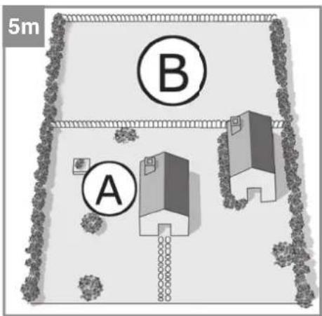
5.7.4 Main area and secondary area (Fig. 5m)
A secondary area (B) refers to a work area that is not directly connected to the main area (A), e.g. a bottleneck. The robot lawn mower cannot reach a secondary area directly and independently.
To be able to mow the secondary area (B) you must carry the robot lawn mower manually into the secondary area (B). The robot lawn mower must be switched on with the main switch (7). Start the robot lawn mower there by pressing the "START A/B" button (64) for 5 seconds. Then close the control panel cover (13). Secondary area mode is activated and the status LED (52) will fl ash green. When the robot lawn mower is in the secondary area (B) it will not try to return to the charging station (19) if the battery charge level is low. The robot lawn mower will mow until the battery is empty. Then you must either charge the battery or carry the robot lawn mower back to the charging station (19).
Important!
The robot lawn mower is allowed to move no more than 1000 m from the charging station (19) or else the GNSS LED (54) will turn yellow and the robot lawn mower cannot be operated in Main Area mode. The mower's distance from the charging station (19) is irrelevant for operation in Secondary Area mode.
5.7.5 Distance from mowed areas not belonging to you
Keep away from mowed areas which do not belong to you but to your neighbors, for example, and which are operated with a perimeter wire. The signal produced by the perimeter wire can lead to problems when your robot lawn mower tries to find its way back to its charging station.
5.8 GNSS module
5.8.1 Calibrating the position of the charging station
The robot lawn mower must calibrate the position of the charging station (19) with the help of a global navigation satellite system (GNSS) in order to find its way back to the search loop and to the charging station (19).
For this purpose you must place the robot lawn mower in ready-to-use condition and with the
main switch (7) activated in the charging station (19). The GNSS LED (54) will flash green during the calibration process and will light up green continuously as soon as the calibration is finished successfully. This process can take several minutes.
Make sure that there is no shielding or roofing which could prevent the positioning operation. Avoid placing the charging station (19) near tall buildings. Keep a reasonable distance away from tall buildings and trees. Under some circumstances calibration might fail due to poor signal coverage.
5.8.2 Mapping
When the robot lawn mower needs to return to the charging station (19), it determines its distance to the charging station (19) with the help of the GNSS module. If the robot lawn mower comes up against a garden boundary or any obstacles on its way to the charging station (19), it will save its position and the mowing area will be mapped. This will help the robot lawn mower to return to the charging station (19) faster in future use.
5.8.3 Deleting the maps
To delete all the GNSS data on your robot lawn mower, switch off the robot lawn mower with the main switch (7) (OFF). Press the lock button (62) and keep it pressed while you simultaneously switch on the robot lawn mower with the main switch (7) (ON). The robot lawn mower will issue an acoustic signal to confirm deletion. Then you must restart the robot lawn mower in the charging station (19) in order to recalibrate the loading station's position. If you carry out any major alterations to the mowing area in your garden it is recommendable to delete the robot lawn mower's mapping. Particular during hot summer months, a large number of yellowed lawn patches could have a detrimental effect on the way the robot lawn mower works. In such cases we recommend you to refrain from using automatic mode and to switch instead to using secondary area mode in suitable parts of the garden. However, this might also lead to corruption of the mapping so that the robot lawn mower is no longer able to work correctly. In such cases: delete the mapping.
5.9 Garden boundaries and their quality
To ensure that your robot lawn mower works safely without a perimeter wire, the robot lawn mower uses the camera unit (15) to check the boundaries of the mowing area. The camera unit (15) analyzes the mowing area lying ahead of it (approx.
GB
1m^2) . If the robot lawn mower comes up against a boundary of the mowing area, it can use various parameters to determine a boundary quality value.
5.9.1 Initialization run – getting started
Make sure that the robot lawn mower's battery is fully charged at the beginning of the initialization run. Then the robot lawn mower can complete the definition of a reference value in one operation. If one battery charge is not enough for the initialization run, the robot lawn mower will automatically return to the charging station (19) and continue its run after charging.
For the reliability of the mowing area boundaries to be determined, an individual reference value per mowing area must be created for the robot lawn mower's operation.
To determine the reference value the robot lawn mower moves as usual in a random direction within the mowing area. If the robot lawn mower comes up against a boundary or an obstacle, it will stop and evaluate the mowing area ahead of it. Then the robot lawn mower will start moving again in a random direction. For safety reasons the initialization run takes place with the mower unit switched off.
If the robot lawn mower comes up against a boundary of the mowing area, this boundary will be evaluated and the guide cable LED (56) will light up. Green signals a reliable boundary of the mowing area and yellow an unreliable boundary. The robot lawn mower indicates the quality of a lawn boundary both in the initialization run and during automatic mode.
For reliable determination of the reference value you need at least 200 contacts with a boundary of the mowing area. The boundary quality value is checked for its reliability after more than 200 contacts. If the robot lawn mower decides that the value is not yet reliable enough, it will continue its initialization run for a further 200 contacts. If the initialization run was successful so that it was possible to create a reliable boundary quality value, the robot lawn mower will begin to mow the mowing area in accordance with its mowing time setting.
If there was no success in creating a reliable reference value, the robot lawn mower will stop and the guide cable LED (56) will flash red. Check the boundaries of the mowing area and correct the boundaries which do not differ clearly from the mowing area. Make sure that the mowing area differs clearly from the surrounding area. Now delete the existing reference value (see 5.9.4) and then repeat the initialization.
5.9.2 Checking the boundary's quality in operation
When the robot lawn mower is in automatic mode, it checks in regular intervals whether the current boundary quality value of the mowing area has changed compared to its reference value. As soon as the robot lawn mower is in the charging station (19), the corresponding status of the last determined comparative boundary quality value will be displayed via the guide cable LED (56). This value is compared at the same time with the reference value determined during the initialization run.
The guide cable (56) lights up green:
The robot lawn mower is situated in the charging station (19) or near the search loop and the deviation from the reference quality value is small.
The guide cable (56) fl ashes yellow:
The robot lawn mower is situated in the charging station (19) or within the search loop and the deviation from the reference quality value has worsened.
The guide cable LED (56) fl ashes red:
The robot lawn mower is situated in the charging station (19) or inside the search loop and the deviation from the reference quality value is too big. The robot lawn mower stays in the charging station (19). Check the boundaries of the mowing area. Then delete the reference value (see 5.9.4) and carry out a new initialization of the boundary quality value.
The guide cable LED (56) is OFF:
• The guide cable (24) is not connected correctly or has been damaged.
• The power supply to the charging station (19) has been interrupted.
- The robot lawn mower is situated outside the search loop.
5.9.3 Operating the robot lawn mower in secondary areas
The robot lawn mower can create an individual value for the main area and the secondary area. This means that you must carry out an initialization run in each new secondary area. You are only allowed to use the robot lawn mower on one secondary area. If you want to mow with the robot lawn mower on an additional secondary area it is absolutely essential to delete the boundary quality value of the secondary area and to carry out an initialization run.
GB
5.9.4 Deleting the values
If the last time you mowed was ages ago, e.g. at the end of the previous season, the boundary quality values might have changed in the meantime. This could lead to mistakes when the new season gets underway. It is recommended therefore to delete the boundary quality value every year at the beginning of the season and to determine a new reference value. This can help to guarantee that the robot lawn mower works safely and reliably.
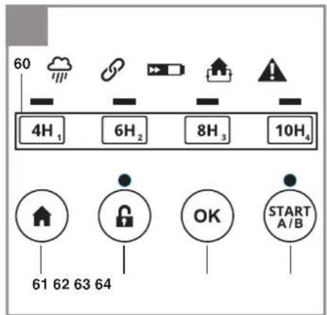
The robot lawn mower must be in locked mode. The lock LED (51) will then flash red permanently. To lock the robot lawn mower you must press the lock button (62). Proceed as follows to delete the values saved for the corresponding areas:
-
Reference value of the main area (A): Press the "OK" button (63) and the "10H" button (60) simultaneously and hold for 3 seconds. An acoustic signal will sound. Place the robot lawn mower in the charging station (19) and restart it in order to carry out a new initialization run.
-
Reference value of the secondary area (B): Press the "OK" button (63) and the "8H" button (60) simultaneously and hold for 3 seconds. An acoustic signal will sound.
5.10 Switching on and checking the installation
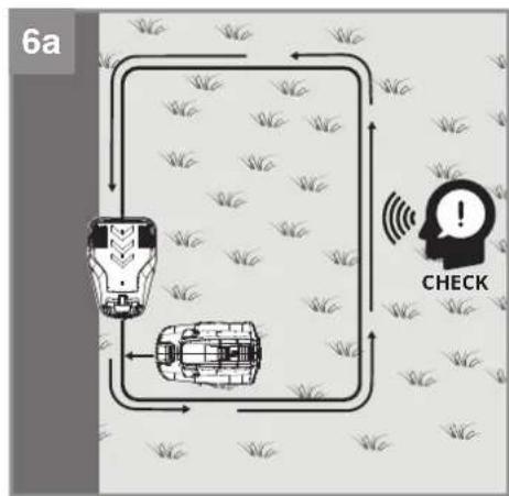
5.10.1 Checking the installation of the guide cable and the charging station (Fig. 6a)
As soon as the LED display (19a) on the charging station (19) lights up green, the mowing area is ready for the robot lawn mower. First check that all the fastening pegs (23) for the guide cable (24) have been fully tapped in.
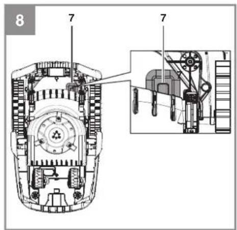
Place the robot lawn mower in the search loop a short distance behind the charging station (19). To check as far as possible the complete distance of the guide cable (24): The robot lawn mower should not yet be on the guide cable (24) but should be facing the guide cable (24). Switch on the main switch (7) (ON) (Fig. 8).
Press the "STOP" button (3) and open the control panel cover (13). Press the lock button (62), unlock the robot lawn mower using the PIN, and confirm your entry with the "OK" button (63) (see the section "Lock mechanism / PIN").
Press the "HOME" button (61). Then close the control panel cover (13). Now the robot lawn mower will search for the guide cable (24) in order to find the charging station (19). First it will travel forwards until it arrives at the guide cable (24). Depending on the situation the robot lawn
mower might stop briefly beforehand in order to re-orientate. Then the robot lawn mower will follow the guide cable (24) counterclockwise. Make sure there are no objects lying on the guide cable (24). The battery of the robot lawn mower will now be fully charged. If any problems occur with docking, you might need to adjust the orientation of the charging station (19) until docking works without any problems.
To stop the robot lawn mower at any time, press the red „STOP“ button (3). When you press the „STOP“ button (3), the robot lawn mower will come to a stop and wait for further instructions. Check in addition those places which lie far away from the search loop and those areas which are connected by bottlenecks. Repeat the process as described above and use the “HOME” button (61) to send the robot lawn mower back to the charging station (19).
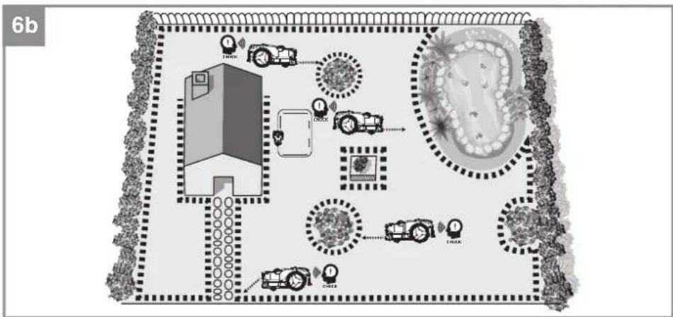
5.10.2 Checking the mowing area (Fig. 6b)
To check the boundaries of the mowing area, walk along the lawn boundary and check if the mowing area is completely surrounded by boundaries or obstacles. Repeat this with all areas which are to be excluded, e.g. flower beds, pools or ponds, and check whether these areas are clearly separated from the mowing area at all points. It is recommended to examine critical points which you doubt that the robot lawn mower will recognize. For this purpose place the robot lawn mower a distance of 1 m away from the point you want to check. The robot lawn mower needs to be facing the point you want checked. Areas protected by a magnetic tape (27) must also be checked. Then start the unlocked robot lawn mower with the help of the "START A/B" button (64). First the robot lawn mower will travel forwards and should then recognize the lawn boundary or the obstacle. You can interrupt the process at any time with the help of the „STOP“ button (3). Repeat this process at all points where you feel unsure.
5.10.3 Checking the position of the charging station (Fig. 6c)
Check the position of the charging station (19) by positioning the robot lawn mower at various points of the lawn after calibration is completed and have the mower search for the charging station (19). First unlock the robot lawn mower, then press the "HOME" button (61) and close the control panel cover (13). You can interrupt the process at any time with the help of the „STOP“ button (3). If necessary adapt the area, the laying of the guide cable (24) and the position of the charging station (19).
GB
5.11 Securing the charging station
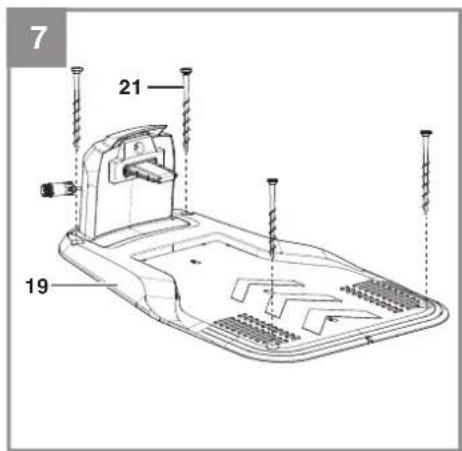
Once the robot lawn mower is working properly and a suitable position for the charging station (19) has been found, the charging station (19) must be fixed in place using the fastening screws (21). Use the hexagon key (22) to secure the fastening screws (21) fully in the ground (Fig. 7).
5.12 Battery charge level indicator
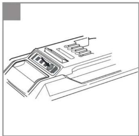
Press the button for the battery charge level indicator. The battery charge level indicator indicates the charge state of the battery by means of 3 LEDs (Fig. 12b).
All 3 LEDs are lit:
The battery is fully charged.
2 or 1 LED(s) are lit:
The battery has an adequate remaining charge.
1 LED fl ashes:
The battery is empty, recharge the battery.
All LEDs blink:
The battery temperature is too low. Remove the battery from the equipment, keep it at room temperature for one day. If the fault reoccurs, this means that the battery has undergone exhaustive discharge and is defective. Remove the battery from the tool. Never use or charge a defective battery.
Important!
When using a multi-Ah pack (e.g. 4-6Ah), always set the higher capacity. Thanks to the gentle charging and discharging of the robot lawn mower there is no need to use the lower capacity in order to extend the working life.
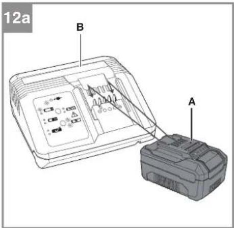
5.13 Charging the battery with the charger In normal operation the battery (A) of the robot lawn mower is charged via the charging station (19). For independent use of the battery (A) from the Power-X-Change series it can also be charged in the external Power-X-Charger. Important! - Depending on the model of your robot lawn mower, it might not come complete with the battery charger (B).
-
Check that your mains voltage is the same as that marked on the rating plate. Insert the power plug of the charger (B) into the socket outlet. The green LED will begin to blink.
-
Insert the battery (A) into the battery charger (B) (Fig. 12a).
-
In the section entitled „Charger indicator“ you will find a table with an explanation of the LED
display on the charger.
The battery can become a little warm during the charging. This is normal.
If the battery pack fails to charge, check:
• Is there voltage at the power socket?
- Is there good contact at the charging contacts?
If the battery pack still fails to charge, please send thecharger
• and the battery pack
to our customer service center.
To ensure that items are properly packaged and delivered when you send them to us, please contact our customer service or the point of sale at which the equipment was purchased.
When shipping or disposing of batteries and cordless tools, always ensure that they are packed individually in plastic bags to prevent short circuits and fi res.
To ensure that the battery pack provides long service, you should take care to recharge it promptly. You must recharge the battery pack when you notice that the performance of the device drops. Never allow the battery pack to become fully discharged. This will cause it to develop a defect.
6. Operation
6.1 Main switch
The robot lawn mower is equipped with a main switch (7). Use the main switch (7) to switch the robot lawn mower on (ON) and off (OFF) (Fig. 8). Once the robot lawn mower has been switched on it will be locked by the PIN.
6.2 Control panel
The control panel (2) can be used to make the settings on your robot lawn mower. The integrated LED display informs you about the status of your robot lawn mower. Familiarize yourself with the controller and the available options.
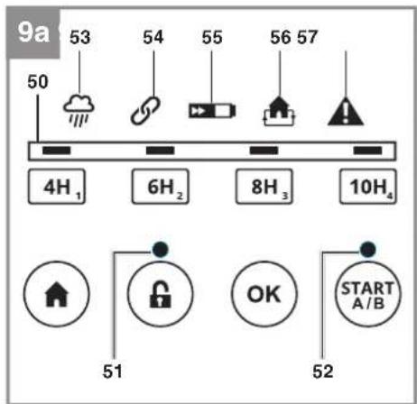
Explanation of the LEDs on the control panel (Fig. 9a)
- Time LEDs: Display of the daily mowing time
- Lock LED: Display of the button lock
- Status LED: Status display of the robot lawn
GB
mower and the mowing area
- Rain sensor LED: Indication as to whether the rain sensor has triggered
- GNSS LED: Status display of the GNSS signal
- Battery LED: Display of the battery charge level
- Guide cable LED: Indication of the boundary quality and whether there is a guide cable fault
- Alarm LED: Display of faults
An overview of important status displays is provided at the end of these instructions in the section "Displays on the robot lawn mower and troubleshooting".
Explanation of the button options on the control panel (Fig. 9b)
-
Buttons for setting the mowing time and for entering the PIN
-
"HOME" button
- Lock button
- "OK" button
- "START A/B" button
6.3 Cutting height adjustment facility
Important! Adjust the cutting height only when the robot lawn mower has been switched off. Do this by pressing the „STOP“ button (3). The cutting height adjustment facility (4) allows the cutting height of the robot lawn mower to be set to infi nitely adjustable settings between 20 and 60 mm, which can be viewed on the scale.
If the grass is taller than 60~mm it must first be shortened to a maximum of 60~mm to avoid exposing the robot lawn mower to excessive load and adversely affecting its operating efficiency. Use a conventional lawn mower or trimmer to do this. After installation has been completed, the cutting height can be adjusted using the cutting height adjustment facility (4). Always start with a higher cutting height and reduce it in small steps until you reach the desired height.
6.4 Locking mechanism / PIN
The locking mechanism prevents the unauthorized use of the robot lawn mower without a valid code. You have to enter a personal four-digit security code for this.
Lock release
- Before you start using the robot lawn mower, you have to enter the correct PIN (standard PIN: "1-2-3-4"). Open the control panel cover
(13) and press the lock button (62). Then enter the PIN slowly in sequence and confirm the entry with the "OK" button (63). The control functions will be unlocked and the lock LED (51) will light up green.
- If you enter an incorrect PIN, the lock LED (51) will fl ash red. Press the lock button (62) and re-enter the PIN.
Lock
If you want to lock the control panel (2), press the lock button (62). The lock LED (51) will now fl ash red permanently.
Standard PIN: New PIN:
1234
Changing the PIN
To change the PIN, proceed as follows.
- Unlock the control panel (2).
- Press the "OK" button (63) and the "4H" button (60) simultaneously and hold for 3 seconds. An acoustic signal will sound.
- Enter a new PIN (four digits). Press the "OK" button (63).
- Repeat step 3 to confirm the new PIN.
- Important! Make a note of the new PIN.
Requesting your PIN if you lose it
Have the receipt and the serial number of the robot lawn mower ready. You need them in order to get your PIN.
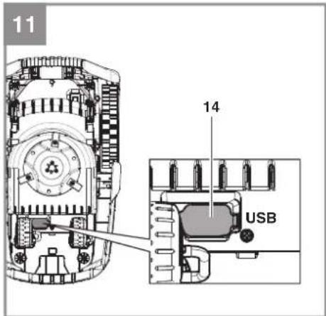
- Connect an empty USB stick to the USB connection (14) as shown (Fig. 11).
- Switch on the main switch (7) (ON).
- The robot lawn mower will automatically save the PUK to your USB stick and will then end the operation with a beep.
- Pull out the USB stick. Import the data from the USB stick to a computer. A text fi le (*.txt) will have been created by the robot lawn mower. This fi le contains a PUK (Personal Unlocking Key). Contact the customer services team to obtain your PIN.
6.5 Settings of the robot lawn mower Setting the mowing time
The robot lawn mower is equipped with a camera unit (15) which can work only in daylight. As soon as twilight sets in, the camera unit (15) of the robot lawn mower will no longer be able to distinguish reliably between the lawn and the lawn's boundaries. Consequently the robot lawn mower will return automatically to the charging station (19) at the onset of twilight. In such a case the set
GB
running time might not be reached.
This also applies when the set start time occurs during twilight or in darkness. Then the robot lawn mower will initially leave the charging station (19), only to return immediately along the guide cable (24) to the charging station (19). This results in the robot lawn mower not working on this day
- Unlock the control panel (2).
- Select the desired mowing time by pressing the corresponding button for setting the mowing time (60):
2.1 If you press the corresponding button (60) briefly, the robot lawn mower will mow each day. This will be indicated by the selected time LED lighting up permanently.
2.2 If you press the corresponding button (60) and keep it pressed for longer (6 seconds), the robot lawn mower will mow every second day. This will be indicated accordingly by the selected time LEDs flashing. - This will be indicated accordingly by the time LEDs (50).
- To confirm the setting, press the "OK" button (63).
The original duration of the set mowing window will be changed accordingly. The then applicable start time will remain unchanged but the duration will be altered to the indicated number of hours.
It is recommended to base the mowing time setting on 8 hours per day for 400m^2 as a guideline. The selected working time must be adapted to take account of the garden's size and complexity.
Resetting the daily start time
To reset the daily start time, press the "OK" button (63) and the "6H" button (60) simultaneously and hold for 3 seconds. A successful reset will be confirmed with 5 beeps. Then restart the robot lawn mower with the button "START A/B" (64). The time at which the change was made is now the daily start time. The number of hours shown is the daily work time.
Starting procedure
- Unlock the control panel (2).
- You can use the button "START A/B" (64) to select the area in which the lawn mower is to work. More details of the two areas can be found in the section "Before using for the first time" under "Mowing area".
2.1 If you press the button "START A/B" (64) briefly, the robot lawn mower will mow in the main area (A). In this case the status LED (52) will
light up green permanently.
2.2 If you press the button "START A/B" (64) and keep it pressed for longer, the robot lawn mower will mow in the secondary area (B). The status LED (52) will then flash green.
3. Close the control panel cover (13).
The robot lawn mower will now operate in accordance with the mowing time setting. The battery charge level is monitored during the work time and displayed via the battery LED (55). Whenever the battery charge level drops to 30%, the robot lawn mower will automatically return to the charging station (19).
Note: A reference value of the quality value is needed to operate the robot lawn mower. This reference value is determined as described in the section "Garden boundaries – Boundary quality value", which is why the robot lawn mower begins initially with its mower unit switched off. If the value was determined already, the robot lawn mower will begin with the starting procedure in accordance with the selected mowing time setting.
Canceling the mowing operation
- To bring the robot lawn mower to an immediate stop, press the „STOP“ button (3).
- Open the control panel cover (13) fully.
- Unlock the control panel (2).
- Press the "HOME" button (61) to send the robot lawn mower back to the charging station (19).
- Close the control panel cover (13).
- Now the robot lawn mower will search for the guide cable (24) in order to find the charging station (19). First it will travel forwards a few meters and then stop in order to re-orientate. This will continue until the robot lawn mower arrives at the guide cable (24). Then the robot lawn mower will follow the guide cable (24) counterclockwise. Make sure there are no objects lying on the guide cable (24).
„STOP“ status:
When you press the „STOP“ button (3), the robot lawn mower will adopt a „STOP“ status. This will be indicated by the time LEDs (50) fl ashing one after the other. The robot lawn mower will interrupt its mowing until this „STOP“ status is canceled. The „STOP“ status can be canceled as follows:
- By unlocking the robot lawn mower and pressing the button „START A/B“ (64) in order to send off the robot lawn mower to mow. Close
GB
the display cover (25).
- By unlocking the robot lawn mower and pressing the button „HOME“ (61) in order to send the robot lawn mower back into the station. Close the display cover (25).
- By unlocking the robot lawn mower and closing the display cover (25) within 5 seconds.
- By unlocking the robot lawn mower and pressing the lock button (62).
7. Cleaning, maintenance and ordering spare parts
Danger!
The equipment must be disconnected from the power supply (pull out the power plug and switch off the equipment by the main switch (7) (OFF) (Fig. 8)) prior to performing any cleaning and maintenance work. Also take the battery (A) out of the robot lawn mower (Fig. 3b).
Caution! Wear working gloves!
7.1 Cleaning the tool
- Keep all safety devices, air vents and the motor housing free of dirt and dust as far as possible. Wipe the equipment with a clean cloth or blow over it with compressed air at low pressure.
- Do not clean the robot lawn mower with running water, particularly at high pressure.
- Clean the equipment regularly with a damp cloth and some soft soap. Do not use cleaning agents or solvents; these might be aggressive to the plastic parts in the equipment. Ensure that no water can get into the interior of the equipment.
- For best results, clean the robot lawn mower with a brush or rag.
- Check the freedom of movement of the blades (10) and the blade plate (11).
- Use cleaning product for metal or very fine abrasive paper to clean the charging contacts on the robot lawn mower (1) and the charging station (19). Clean them in order ensure efficient charging.
7.2 Maintenance
- Check the lens of the camera unit (15) regularly for signs of dirt and clean if necessary. The lens is likely to become dirty particularly when it rains. Do not use any aggressive cleaning agents or solvents.
• Worn or damaged blades (10) and their faste-
ning screws must always be replaced as a set.
- Replace excessively worn or damaged parts immediately.
- In order to ensure that you enjoy the equipment for many years to come, all screwed parts, as well as the wheels and axles, should be cleaned and lubricated.
- Keeping your robot lawn mower in good condition not only ensures a long lifespan and high performance, but also enables the equipment to thoroughly cut your grass with minimal effort.
- The blades (10) are subject to more wear and tear than any other component. Therefore, routinely check the condition of the blades (10) and make sure that they are tightly fastened. An excessively vibrating robot lawn mower can indicate that the blades (10) are damaged or have become deformed from striking an object. If the blades (10) are worn or damaged, they must be replaced immediately.
- Check the appearance of the cut lawn at regular intervals. The grass will not be cleanly cut if the blades are not sharp. This can result in the surface of the lawn drying out easily and turning brown. It is important therefore to change the blades regularly in order to obtain a clean and straight cut.
- Check the bottom of the robot lawn mower for dirt at regular intervals. Clean the robot lawn mower regularly. Remove heavy soiling immediately.
- Heavy soiling of the robot lawn mower is possible in the first weeks of its use if you previously worked with a conventional lawn mower. In these first few weeks you should check the bottom of your robot lawn mower more often.
- Shorten the lawn only in small steps in order to prevent heavy soiling.
- There are no other parts inside the tool which require maintenance.
7.2.1 Replacing the blades
Use only original blades or correct performance and safety cannot be guaranteed.
The robot lawn mower is equipped with three blades (10) fitted to a blade plate (11). These blades (10) have a service life of up to 3 months (if they do not strike any obstacles). Please replace all three blades (10) at the same time to ensure that there is no possibility of any impairment to the efficiency and balance of your equipment.
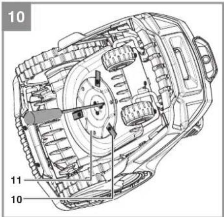
To change the blades (10), proceed as follows (Fig. 10 - Caution! - Wear work gloves:
GB
- Use a screwdriver to block the rotation of the blade plate (11). Do this by inserting the screwdriver through the holes in the blade plate (11) and the protective ridge.
- Undo the fastening screws.
- Remove the blades (10) and replace them with new ones. Always replace all three blades (10) as a set.
- Then retighten the fastening screw. Check that the new blades (10) are able to rotate freely.
Perform a general inspection of the robot lawn mower at regular intervals and remove any deposits which have accumulated. At the start of each season, ensure that you check the condition of the blades (10). If repairs are necessary, please contact our customer service center. Use only genuine spare parts.
7.2.2 Software update
If you want to update the software, copy the new software to an empty USB stick (format the USB stick first if necessary). Make sure that the battery is fully charged before you carry out the following steps.
- With the robot lawn mower switched on, place it in the mowing area. The robot lawn mower must not be in the charging station (19) during the software update.
- Connect a USB stick to the USB connection as shown (Fig. 11).
3.1 The robot lawn mower will now install the two files one after the other. Alternatively the files can be updated one at a time. In this case you must first switch off the robot lawn mower with the main switch (OFF).
3.2 System update (example of file name: CMK_3100.1.2.3.4.bin): Press the button "4H" for the mowing time setting (60) and simultaneously switch on the robot lawn mower with the main switch (7) (ON).
3.3 Camera update (example of file name: Camera_1.2.3.4.bin): Press the button "10H" for the mowing time setting (60) and simultaneously switch on the robot lawn mower with the main switch (7) (ON). - The time LEDs (50) will flash during the update process.
- When finished, the robot lawn mower will emit a continuous beep sound. If successful, all 4 time LEDs (50) will light up. If uncompleted, all 4 time LEDs (50) will go out and you will need to repeat the software update.
- Pull out the USB stick and restart the robot lawn mower with the main switch (7).
7.2.3 Repairing the guide cable
First disconnect the charging station (19) from the power supply. If the guide cable (24) has been severed at any point, use the supplied cable connectors (25) to repair it. To do so, insert both ends of the severed guide cable (24) into the cable connector (25) and squeeze it with the help of a pair of pliers. Connect the power plug to the socket outlet. Finally, check the LED display (19a) on the charging station (19) to see if the function is working.
7.3 Ordering spare parts
Please provide the following information on all orders for spare parts:
- Type of unit
• Article number of the unit
• ID number of the unit
- Spare part number of the required spare part
For the latest prices and information go to www.Einhell-Service.com
Replacement blades Art. No.: 34.140.20
8. Storage
Fully charge the battery (A) before putting it into storage over winter and switch off the robot lawn mower at the main switch (7) (OFF). Take the battery (A) out of the equipment. Disconnect the power supply unit (20) from the power supply and the charging station (19).
The guide cable (24) can be left outdoors over winter. However, make sure that the connections are protected against corrosion. To do so, disconnect the connections of the guide cable (24) from the charging station (19).
Store the equipment and accessories out of children's reach in a dark and dry place at above freezing temperature. The ideal storage temperature is between 5 and 30^ . Store the equipment in its original packaging.
GB
9. Transport
- Switch off the equipment at the main switch (7) (OFF) (Fig. 8).
• Fit transport guards if available. - Protect the machine from damage and the strong vibrations that can occur particularly when transporting in vehicles.
- Secure the machine against slipping and tipping over.
- Carry the robot lawn mower by the carry-handle (6) with the blade plate (11) facing away from your body.
10. Disposal and recycling
The equipment is supplied in packaging to prevent it from being damaged in transit. The raw materials in this packaging can be reused or recycled. The equipment and its accessories are made of various types of material, such as metal and plastic. Never place defective equipment in your household refuse. The equipment should be taken to a suitable collection center for proper disposal. If you do not know the whereabouts of such a collection point, you should ask in your local council offices.
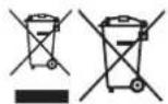
For EU countries only
Never place any electric power tools in your household refuse.
To comply with European Directive 2012/19/EC concerning old electric and electronic equipment and its implementation in national laws, old electric power tools have to be separated from other waste and disposed of in an environment-friendly fashion, e.g. by taking to a recycling depot.
Recycling alternative to the return request: As an alternative to returning the equipment to the manufacturer, the owner of the electrical equipment must make sure that the equipment is properly disposed of if he no longer wants to keep the equipment. The old equipment can be returned to a suitable collection point that will dispose of the equipment in accordance with the national recycling and waste disposal regulations. This does not apply to any accessories or aids without electrical components supplied with the old equipment.
Please note that batteries and lamps (e.g. light bulbs) must be removed from the tool before it is disposed of.
The reprinting or reproduction by any other means, in whole or in part, of documentation and papers accompanying products is permitted only with the express consent of the Einhell Germany AG.
Subject to technical changes
GB
11. Charging station display and troubleshooting
| LED display (19a) | Description Solution | |
| Off - No power supply | - Check the power supply | |
| Lit green - Ready for | mowing- The battery is fully charged- The guide cable (24) is connected | |
| Flashing green - The | guide cable (24) is severed | - Examine the guide cable (24) for a break |
| Lit red - The battery is | being charged - Wait until the battery is fully charged |
12. Robot lawn mower display and troubleshooting
| Rain sensor LED (53) | Description / possible cause Solution | |
| Flashing yellow - The rain sensor (5) has tripped. | - Wait until the robot lawn mower is dry.- A detailed description of the sensor can be found in section 5.2. | |
| GNSS LED (54) | Description / possible cause $ Solution | |
| Flashing green - The robot lawn mower searches for a GNSS connection and calibrates the position of the charging station (19).- The GNSS signal is not precise | - Wait for calibration to end.- If the GNSS LED (54) fl ashes permanently, the received signal is very weak (blocked by a building or tree) and the position of the charging station (19) should be adapted. | |
| Lit green - The robot lawn mower has calibrated the position pf the charging station (19) with the help of GNSS.- The GNSS signal is precise | - The robot lawn mower is ready. | |
| Flashing yellow - There is no GNSS signal - Make sure that the robot lawn mower is outside and that the GNSS signal is not being blocked. | ||
| Lit yellow | - The robot lawn mower is too far from the charging station (19). | - Move the robot lawn mower into the moving area which is near the charging station (19).- Switch off the main switch (7) (OFF) and then switch it back on again (ON) to re-start the robot lawn mower. |
| Lit red - Hardware fault on the GNSS module | - Contact your customer service center. | |
GB
| Battery LED (55) | Description / possible cause Solution | |
| Lit green - The battery is fully charged - The robot lawn mower is ready | ||
| Lit red - The charge status of the bat-tery is low | - The robot lawn mower travels to the charging station (19) in order to charge the battery. | |
| Flashing green - The battery is being charged - The robot lawn mower is in the charging station (19) and is being charged. | ||
| Flashing red Battery fault:- The robot lawn mower has a battery fault- The battery cannot be charged- The battery has reached the end of its service life | - Make sure that the battery was correctly fitted.- Check whether the main switch (7) is switched on (ON) while the robot lawn mower is in the charging station (19).- Check the position of the charging station (19).- Replace the battery if necessary. | |
| Lit yellow Overheating fault:- The temperature of the bat-tery is too high/too low or the controller is overheated- If the battery temperature exceeds 65 °C, the robot lawn mower will return to the charging station (19).- If the battery temperature exceeds 45°C or drops below 0°C, charging will be stopped and the robot lawn mower will wait at the charging station (19). | - Set the work time in summer to the early hours of morning and avoid running the robot lawn mower during the hours of the day when it is hot.- After the battery or controller has cooled down to the permissible temperature range, the robot lawn mower automatically returns to programmed operation. | |
GB
| Guide cable LED (56) | Description / possible cause | Solution |
| Lit green The robot lawn mower is situated in the charging station (19) or near the search loop and the deviation from the reference quality value is small. | - The robot lawn mower is ready | |
| Flashing yellow The robot lawn mower is situated in the charging station (19) or within the search loop and the deviation from the reference quality value has worsened. | The robot lawn mower is ready. If necessary check the boundaries of the mowing area as they might become worse. The robot lawn mower is then unable to continue working | |
| Flashing red The robot lawn mower is situated in the charging station (19) or inside the search loop and the deviation from the reference quality value is too big. The robot lawn mower stays in the charging station (19). | Check the boundaries of the mowing area. Then delete the reference value and carry out a new initialization of the boundary quality value. | |
| Lit red Camera fault: The robot lawn mower does not receive a signal from the camera unit. | Switch off the main switch (7) (OFF) and then switch it back on (ON) again to restart the robot lawn mower. | |
| Off - The guide cable (24) has been damaged.- The power supply to the charging station (19) has been interrupted.- The robot lawn mower is situated outside the search loop. | Check whether the LED display (19a) on the charging station (19) is lit green.- Make sure that the guide cable (24) is laid correctly and centrally underneath the charging station (19).- Check the position of the charging station (19). | |
GB
Alarm LED (57) Description / possible cause Solution
| Lit yellowThe moweris lifted:- The lifting sensor has been continually tripped for 10 seconds | Press the „STOP“ button (3) in order to open the control panel cover (13). Re-start the mowing operation on the control panel (2):- If this fault occurs frequently, check the mowing area for obstacles taller than 10 cm and either remove them or separate them from the mowing area. |
| The mower is blocked:- The obstacle sensor has been activated several times in one minute- The obstacle sensor has been constantly activated for 10 seconds- The obstacle sensor has been activated three times on the way back to the charging station (19) | Press the „STOP“ button (3) in order to open the control panel cover (13). Re-start the mowing operation on the control panel (2):- Check whether the robot lawn mower is blocked by an obstacle or jammed between trees, bushes, etc. Remove the obstacle or avoid this area.- If this fault occurs frequently, check the mowing area. Pay particular attention to tight angles, corridors, fences, rocks, etc.- Check whether the grass is too tall and blocks the robot lawn mower. If this is the case, mow the grass to below 60 mm. |
| Too close to the station:- The robot lawn mower was sent back too close to the charging station (19) | Press the „STOP“ button (3) in order to open the control panel cover (13). Re-start the mowing operation on the control panel (2):- The robot lawn mower should be sent back to the charging station (19) at a minimum distance of 2 m. |
| Toppled:- The robot lawn mower was constantly tilted for 10 seconds- The robot lawn mower has been tilted for a long time in one direction | Press the „STOP“ button (3) in order to open the control panel cover (13). Re-start the mowing operation on the control panel (2):- Move the robot lawn mower to a level area and restart it.- If the robot lawn mower is tilted because of a steep slope in the mowing area, separate this area in order to avoid severe inclines. |
GB
| Alarm LED (57) Description / possible cause Solution | ||
| Lit yellow Wheel fault: | - The rear wheels (8) were lifted by an obstacle- The rear wheels (8) can rotate freely due to unevenness in the lawn | Press the „STOP“ button (3) in order to open the control panel cover (13). Re-start the mowing operation on the control panel (2):- Move the robot lawn mower to a level area and restart |
| „STOP“ button fault:The control panel cover (13) is open and a button on the control panel (2) was pressed but the „STOP“ button (3) was not activated | Press the „STOP“ button (3) in order to open the control panel cover (13). Re-start the mowing operation on the control panel (2):- Check if the control panel cover (13) can be freely opened and closed with the „STOP“ button (3).- Check the functionality of the „STOP“ button (3). | |
| Outside:The robot lawn mower cannot recognize any lawn area or lawn boundaries and lies outside the mowing area. | Press the „STOP“ button (3) in order to open the control panel cover (13). Re-start the mowing operation on the control panel (2):- Check that the robot lawn mower is inside the mowing area. | |
| Lit red Sensor fault: | - The robot lawn mower was stopped due to a sensor faultMotor fault / motor overcurrent:- The robot lawn mower has come to a stop because of overcurrent in the motor or because of a motor fault | Switch off the main switch (7) (OFF) and then switch it back on (ON) again to restart the robot lawn mower.Switch off the main switch (7) (OFF) and then switch it back on (ON) again to restart the robot lawn mower.- Check the height of the grass in the mowing area and, if necessary, mow the grass to below 60 mm using a conventional lawn mower.- Increase the cutting height. Always start with a higher cutting height and reduce it in small steps until you reach the desired height.- Inspect the blade plates (11) and wheels for dirt and give these parts a thorough clean.- Check the rear wheels and the blade plate (11) for blockages. If you are unable to remove the blockages, contact the responsible customer service center. |
| Operating fault:- The robot lawn mower was stopped due to an operating fault | Switch off the main switch (7) (OFF) and then switch it back on (ON) again to restart the robot lawn mower. | |
| Flashing red Magnetic tape fault: | The robot lawn mower does not receive a signal from the magnetic tape sensor. | Switch off the main switch (7) (OFF) and then switch it back on (ON) again to restart the robot lawn mower. |
GB
Troubleshooting
| Fault Possible cause Remedy | ||
| The robot lawn mower comes to a stop in the mowing area. The robot lawn mower cannot be switched on: | - Battery voltage too low- Fault in the power circuit or the electronic components | - Bring the robot lawn mower back to the charging station (19) for charging.- Switch on the main switch (7) (ON).- Contact your customer service center.- Check the position of the charging station (19) and the maximum distance from the charging station (19)- Please use a battery with higher capacity- Caution: When using a Multi-Ah battery (e.g. 4-6 Ah), set the higher capacity. Thanks to the gentle charging and discharging of the robot lawn mower there is no need to use the lower capacity in order to extend the working life. |
| The robot lawn mower cannot move into the charging station. | - The charging station (19) is not correctly installed. | - Make sure that the LED display (19a) on the charging station (19) is lit green.- Make sure that the guide cables (24) are connected at the charging station (19) and that the front guide cable (24) is laid in the middle underneath the charging station (19).- Make sure that the charging station (19) is positioned correctly. |
| The robot lawn mower is very loud. | - Damaged blades (10)- A large amount of foreign bodies adhere to the blades (10)- The robot lawn mower has started too close to obstacles- Damaged blade drive or drive motor- Other parts of the robot lawn mower are damaged | - Replace the blades (10). The 3 blades (10) must all be replaced together at the same time.- The operating efficiency of the robot lawn mower is dependent on the sharpness of the blades (10). You should therefore ensure that the blades (10) are maintained in good condition.- To avoid cutting yourself, be sure to switch off the robot lawn mower and wear work gloves while you clean the blades (10).- Arrange for the motor to be repaired or replaced by your customer service center. |
| The robot lawn mower stays in the charging station. The robot lawn mower keeps returning to the charging station. | - Incorrect work time settings- The battery charge level is too low and drops below 30%.- The rain sensor has tripped.- The robot lawn mower has become overheated.- Twilight is falling, making it impossible for the camera unit to work correctly. | - Check the work time settings.- The robot lawn mower will begin and end its work in accordance with the set time window. Outside this time window the robot lawn mower stays in the charging station (19). |
GB
Troubleshooting
| Fault Possible cause Remedy | ||
| The robot lawn mower cannot fi nd the charging station | - The charging station (19) is in a position that receives only a weak GNSS signal- Obstacles in the immediate vicinity of the guide cable loop are preventing the mower from reaching the loop. | - Adapt the position of the charging station (19) and delete the mapping as described in the operating instructions.- Adapt the shape of the guide cable loop / enlarge the guide cable loop. |
IMPORTANT! A severed guide cable and consequential damages are not covered by the warranty!
Magnetic tape troubleshooting (27)
| Fault Possible cause Remedy | ||
| The robot lawn mower fails to recognize the magnetic tape (27) and travels over it and past it. | - The magnetic tape (27) is laid too deep in the ground.- The magnetic tape (27) does not work properly because the outside temperature is too high. | - Lay the magnetic tape (27) on the ground or at a depth of approx. 5 cm in the ground.- Wait for the temperature to cool. Avoid operating the robot lawn mower during the hot hours of the day. |
| The robot lawn mower stops or travels out of control when it is near the boundary area. | - The magnetic tape (27) is laid too close to the guide cable (24). The distance between two independent boundary areas with magnetic tape (27) is too small.- Interference arises in the mowing area due to electric cables. | - Keep a distance of at least 80 cm between the guide cable (24) and the magnetic tape (27) or between two boundary areas.- Avoid electric cables which run through the mowing area. Position the charging station (19) at the edge of the mowing area. Keep away from mowed areas which do not belong to you but to your neighbors, for example, and which are operated with a perimeter wire. |
| The robot lawn mower intrudes in the boundary area. | - The robot lawn mower slips over the magnetic tape (27). | - Avoid laying the magnetic tape (27) on gradients.- Take account of the specified conditions of installation. |
13. FREELEXO CAM data protection notice
Einhell Germany AG is delighted that you are using the FREELEXO CAM robot lawn mower. The protection of personal data is an important concern for us. Below is a description of the data processed in general when the equipment is used.
• Location of the charging station
The location of the charging station is determined by means of GNSS positioning and saved locally on the robot lawn mower. This is required in order to navigate the mower back to the charging station when it has finished its mowing work. When servicing is required, this information can be read out of the equipment physically via the logfi le.
• Sunrise time and sunset time
Sunrise time and sunset time are determined by means of GNSS positioning and saved locally on the robot lawn mower. This is necessary so that the equipment can be started only in a time interval when the camera unit is able to generate images with sufficient brightness. When servicing is required, this information can be read out of the equipment physically via the logfile.
• Images produced by the camera unit
Images generated by the camera unit are saved locally on the robot lawn mower. This is required by the system in order to constantly improve the robot lawn mower's algorithm. On the mower you will find images which were generated during the last 15 minutes of mowing work. This data set is overwritten continuously. No images are generated when the mower is situated in the charging station or is looking for the charging station. When servicing is required, these images can be read out locally in order to understand any faults which have occurred. These images are then deleted.
Both the location-specific data and the generated images can be deleted from the equipment by you yourself. In this case you must first switch off the robot lawn mower with the main switch. By simultaneously pressing the lock button (for deletion of GNSS data) or the "OK" button (for deletion of camera images) and switching on the robot lawn mower with the main switch you can delete the saved data. An acoustic signal will sound on the equipment to confirm deletion.
Detailed documentation on our data protection guidelines can be found on our homepage under "Data protection".
GB
14. Charger indicator
| Indicator status | Explanations and actions | |
| Red LED Green LED | ||
| Off Flashing | Ready for use | The charger is connected to the mains and is ready for use; there is no battery pack in the charger |
| On Off Charging | The charger is charging the battery pack in quick charge mode. The charging times are shown directly on the charger.Important! The actual charging times may vary slightly from the stated charging times depending on the existing battery charge. | |
| Off On The battery is charged and ready for use. (READY TO GO) | The unit then changes over to gentle charging mode until the battery is fully charged.To do this, leave the rechargeable battery on the charger for approx. 15 minutes longer.Action:Take the battery pack out of the charger. Disconnect the charger from the mains supply. | |
| Flashing Off | Adapted charging | The charger is in gentle charging mode.For safety reasons the charging is performed less quickly and takes more time. The reasons can be:- The rechargeable battery has not been used for a very long time.- The battery temperature is outside the ideal range.Action:Wait for the charging to be completed; you can still continue to charge the battery pack. |
| Flashing Flashing Fault | Charging is no longer possible. The battery pack is defective.Action:Never charge a defective battery pack.Take the battery pack out of the charger. | |
| On On Temperature fault | The battery pack is too hot (e.g. due to direct sunshine) or too cold (below 0^ ).Action:Remove the battery pack and keep it at room temperature (approx. 20^ ) for one day . | |
GB
Service information
We have competent service partners in all countries named on the guarantee certificate whose contact details can also be found on the guarantee certificate. These partners will help you with all service requests such as repairs, spare and wearing part orders or the purchase of consumables.
Please note that the following parts of this product are subject to normal or natural wear and that the following parts are therefore also required for use as consumables.
| Category Example | |
| Wear parts* Battery | |
| Consumables* Blades | |
| Missing parts |
* Not necessarily included in the scope of delivery!
In the effect of defects or faults, please register the problem on the internet at www.Einhell-Service.com. Please ensure that you provide a precise description of the problem and answer the following questions in all cases:
• Did the equipment work at all or was it defective from the beginning?
• Did you notice anything (symptom or defect) prior to the failure?
• What malfunction does the equipment have in your opinion (main symptom)?
Describe this malfunction.
GB
Warranty certifi cate
Dear Customer,
All of our products undergo strict quality checks to ensure that they reach you in perfect condition. In the unlikely event that your device develops a fault, please contact our service department at the address shown on this guarantee card. You can also contact us by telephone using the service number shown. Please note the following terms under which guarantee claims can be made:
- These guarantee terms apply to consumers only, i.e. natural persons intending to use this product neither for their commercial activities nor for any other self-employed activities. These warranty terms regulate additional warranty services, which the manufacturer mentioned below promises to buyers of its new products in addition to their statutory rights of guarantee. Your statutory guarantee claims are not affected by this guarantee. Our guarantee is free of charge to you.
- The warranty services cover only defects due to material or manufacturing faults on a product which you have bought from the manufacturer mentioned below and are limited to either the rectification of said defects on the product or the replacement of the product, whichever we prefer. Please note that our devices are not designed for use in commercial, trade or professional applications. A guarantee contract will not be created if the device has been used by commercial, trade or industrial business or has been exposed to similar stresses during the guarantee period.
-
The following are not covered by our guarantee:
-
Damage to the device caused by a failure to follow the assembly instructions or due to incorrect installation, a failure to follow the operating instructions (for example connecting it to an incorrect mains voltage or current type) or a failure to follow the maintenance and safety instructions or by exposing the device to abnormal environmental conditions or by lack of care and maintenance.
- Damage to the device caused by abuse or incorrect use (for example overloading the device or the use or unapproved tools or accessories), ingress of foreign bodies into the device (such as sand, stones or dust, transport damage), the use of force or damage caused by external forces (for example by dropping it).
-
Damage to the device or parts of the device caused by normal or natural wear or tear or by normal use of the device.
-
The guarantee is valid for a period of 24 months starting from the purchase date of the device. Guarantee claims should be submitted before the end of the guarantee period within two weeks of the defect being noticed. No guarantee claims will be accepted after the end of the guarantee period. The original guarantee period remains applicable to the device even if repairs are carried out or parts are replaced. In such cases, the work performed or parts fitted will not result in an extension of the guarantee period, and no new guarantee will become active for the work performed or parts fitted. This also applies if an on-site service is used.
-
To make a claim under the guarantee, please register the defective device at: www.Einhell-Service.com. Please keep your bill of purchase or other proof of purchase for the new device. Devices that are returned without proof of purchase or without a rating plate shall not be covered by the guarantee, because appropriate identification will not be possible. If the defect is covered by our guarantee, then the item in question will either be repaired immediately and returned to you or we will send you a new replacement.
Of course, we are also happy offer a chargeable repair service for any defects which are not covered by the scope of this guarantee or for units which are no longer covered. To take advantage of this service, please send the device to our service address.
Also refer to the restrictions of this warranty concerning wear parts, consumables and missing parts as set out in the service information in these operating instructions.
F
Sommaire
PIN standard: Nuovo PIN:
1234

Cambiare PIN
6.1 Interruptor principal
Acendem 2 ou 1 LED(s):
6.1 Interruptor principal
PIN standard: novo PIN:
1234
Alterar o PIN
Standart PIN: Yeni PIN:
1234
PIN değiştir
X 2006/42/EC
Annex IV
Notified Body:
Reg. No.:
□2000/14/EC_2005/88/EC
□ Annex V
□ Annex VI
Noise: measured L_WA = dB (A) ; guaranteed L_WA = dB (A)
P = kW; L/∅ = cm
Notified Body:
□2012/46/EU_(EU)2016/1628
Emission No.
Standard References: EN 60335-1 :2012/A15:2021; EN 50636-2-107:2015/A3:2021;
EN 62233:2008; EN IEC 55014-1:2021; EN IEC 55014-2:2021; EN IEC 61000-3-2:2019/A1:2021;
EN 61000-3-3:2013/A1:2019/A2:2021; EN 301 489-1V2.2.3:2019; Draft EN 301 489-3V2.3.0:2022;
EN 301 489-19V2.2.1:2022; EN 303 447V1.3.1:2022; EN 303 413V1.2.1:2021; EN 50663:2017; EN 62311:2008;
Subject to change without notice
Archive-File/Record: NAPR028474
Documents registrar: Thomas Fischer
Wiesenweg 22, D-94405 Landau/Isar
* GB Robot lawn mower. * Tendeuse robot - R'Orac tagliarbe. * DKN Robotplaneidpper - S Rotograkiplare - CZ Robotelki selekska - SK Robotelki kosekke. NI Masilotot - E Robot corteolaped * RIN Robotbintechanliknik - SLO Robotina kolinika - H Roziotinyrd - RO Robot do tuns gezunol - GR Kizoxomatka poumit - P Robto canta-relas. HRVBIH Robot ka bedinju - RS Robotaka kosaica - PC Koslarka automatyczna - TR Cim bime robotu - RUS Robot-pazanoucosilna - EE Robotmiduk - LV Robotizers zalas plavejs - LT Vejos povima robotas - BG Koszaha potor UKR Robot-pazanoucosnika - MK Robotisiranra koszaha za rege

Declaration of conformity
We, Einhell UK Ltd
Champions Business Park, First Floor Unit 10, Arrowe Brook Rd, Upton, Wirral CH49 0AB, United Kingdom
declare the conformity to UK standards and legislation was assessed for:
Robot Lawn Mower FREELEXO CAM (Einhell)
UK legislation
□ Simple Pressure Vessels (Safety) Regulation
□ Electrical Equipment (Safety) Regulation
X Radio Equipment Regulation
□ Personal Protective Equipment Regulation
☐ The Ecodesign for Energy-Related Products and Energy Information Regulation
X The Restriction of the Use of Certain Hazardous Substances in Electrical and Electronic Equipment Regulation
□ Noise Emission in the Environment by Equipment for use Outdoors Regulation
Electromagnetic Compatibility Regulation
□ Measuring Instruments Regulation
□ Pressure Equipment (Safety) Regulation
Annex V
Annex VI
Noise:measuredL ww = dB (A); guaranteed L ww = dB (A)
P = kW; L/∅ = cm
UK Approved Body:
X Supply of Machinery (Safety) Regulation
Annex IV
UK Approved Body:
UKTE Certifi cate No.:
Standard References: BS EN 60335-1; BS EN 50636-2-107; BS EN 62233; BS EN IEC 55014-1; BS EN IEC 55014-2; BS EN IEC 61000-3-2; BS EN 61000-3-3; BS EN 301 489-1; BS EN 301 489-3; BS EN 301 489-19; BS EN 303 447; BS EN 303 413; BS EN 50663; BS EN 62311;
Wirral, 2022.12.01

Archive-File/Record: NAPR028474
Article Number: 34.139.90 I.-No.: 21022
Subject to change without notice Wiesenweg 22, 94405 Landau/Isar, Germany
Documents registrar: Thomas Fischer
EH 12/2022 (01)


- D
- Inhaltsverzeichnis
- GB
- Danger!
- Safety Information
- Warning!
- Explanation of the symbols used (see Fig. 13)
- Important!
- Layout and items supplied
- Layout (Fig. 1/2)
- Items supplied and unpacking
- Scope of delivery, assembly material and accessories (some not included):
- Required aids (not supplied)
- Intended use
- Technical data
- Starting up
- How it works
- Sensors
- • Lifting sensor:
- - Tilting sensor:
- - Obstacle sensor:
- - Camera unit:
- • Distance sensors:
- • Magnetic tape sensor:
- - Rain sensor:
- • GNSS module:
- Preparations
- Calculating the gradient of the lawn
- Installing the battery
- Charging station
- Position of the charging station
- Localization of the charging station
- Connecting the charging station to the power supply unit
- Information about charging
- Guide cable
- Laying the guide cable
- • Installation on the ground
- • Installation in the ground
- Installing the search loop
- Connecting the charging station
- Mowing area - Obstacles and mowing area boundaries
- Lawn boundary
- - Bottlenecks
- • Distance from the lawn boundary
- • Lawn boundary with water
- - Lawn boundary with a raised edge higher than 25 cm
- - Lawn boundary with a raised edge higher than 10 cm
- Obstacles
- - Obstacles with a height over 25 cm (Fig. 5f)
- - Obstacles with a height under 25 cm (Fig. 5g)
- Magnetic tape (Fig. 5h-j)
- Main area and secondary area (Fig. 5m)
- Distance from mowed areas not belonging to you
- GNSS module
- Calibrating the position of the charging station
- Mapping
- Deleting the maps
- Garden boundaries and their quality
- Initialization run – getting started
- Checking the boundary's quality in operation
- The guide cable (56) lights up green:
- The guide cable (56) fl ashes yellow:
- The guide cable LED (56) fl ashes red:
- The guide cable LED (56) is OFF:
- Operating the robot lawn mower in secondary areas
- Deleting the values
- Switching on and checking the installation
- Checking the installation of the guide cable and the charging station (Fig. 6a)
- Checking the mowing area (Fig. 6b)
- Checking the position of the charging station (Fig. 6c)
- Securing the charging station
- Battery charge level indicator
- All 3 LEDs are lit:
- or 1 LED(s) are lit:
- LED fl ashes:
- All LEDs blink:
- Operation
- Main switch
- Control panel
- Explanation of the LEDs on the control panel (Fig. 9a)
- Explanation of the button options on the control panel (Fig. 9b)
- Cutting height adjustment facility
- Locking mechanism / PIN
- Lock release
- Lock
- Standard PIN: New PIN:
- 1234
- Changing the PIN
- Requesting your PIN if you lose it
- Settings of the robot lawn mower Setting the mowing time
- Resetting the daily start time
- Starting procedure
- Canceling the mowing operation
- „STOP“ status:
- Cleaning, maintenance and ordering spare parts
- Cleaning the tool
- Maintenance
- Replacing the blades
- Software update
- Repairing the guide cable
- Ordering spare parts
- Storage
- Transport
- Disposal and recycling
- Charging station display and troubleshooting
- Robot lawn mower display and troubleshooting
- FREELEXO CAM data protection notice
- • Location of the charging station
- • Sunrise time and sunset time
- • Images produced by the camera unit
- Charger indicator
- Service information
- Warranty certifi cate
- F
- Sommaire
- Cambiare PIN
- Interruptor principal
- Acendem 2 ou 1 LED(s):
- PIN standard: novo PIN:
- Alterar o PIN
- Standart PIN: Yeni PIN:
- PIN değiştir
- Declaration of conformity
- Robot Lawn Mower FREELEXO CAM (Einhell)
- UK legislation
Brand : EINHELL
Model : GECH 3665 Li
Category : Hedge Trimmers