PSH Classic - Boiler STIEBEL ELTRON - Free user manual and instructions
Find the device manual for free PSH Classic STIEBEL ELTRON in PDF.
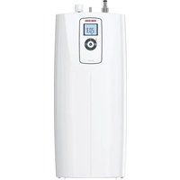
| Product type | Electric pressure water heater |
| Available models | PSH 50, PSH 80, PSH 100, PSH 120, PSH 150, PSH 200 Classic |
| Nominal capacity | From 53 L (PSH 50) to 192 L (PSH 200) |
| Dimensions (PSH 100 Classic) | Height 964 mm, Depth 483 mm, Diameter 475 mm |
| Empty weight (PSH 100 Classic) | 28 kg |
| Full weight (PSH 100 Classic) | 128 kg |
| Power supply | 230 V, 1.8 kW, single phase 1/N/PE, 50/60 Hz |
| Temperature adjustment range | 30 °C to 70 °C (economy position 60 °C) |
| Frost protection | Yes, active from 7 °C (requires power supply) |
| Energy efficiency class | C |
| Protection rating | IP24 |
| Maximum admissible pressure | 0.6 MPa (6 bar) |
| Maximum admissible temperature | 95 °C |
| Maximum flow rate | 23.5 L/min |
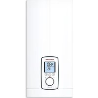
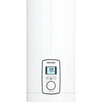
| Main functions | Electric heating of domestic water, continuous temperature adjustment, operating indicator light, temperature indicator |
| Maintenance and cleaning | Clean with a damp cloth; descale the heating element regularly; check the protection anode after 1 year then periodically |
| Safety | Safety valve supplied, safety limiter, frost protection, double insulation (IP24) |
| Spare parts and repairability | Heating element, thermostat, safety limiter, protection anode, anti-corrosion resistor (560 Ω) available |
| General information | Wall mounting, hydraulic connection G 1/2", fixed power cable, residual current device (RCD) required |
Frequently Asked Questions - PSH Classic STIEBEL ELTRON
User questions about PSH Classic STIEBEL ELTRON
0 question about this device. Answer the ones you know or ask your own.
Ask a new question about this device
Download the instructions for your Boiler in PDF format for free! Find your manual PSH Classic - STIEBEL ELTRON and take your electronic device back in hand. On this page are published all the documents necessary for the use of your device. PSH Classic by STIEBEL ELTRON.
USER MANUAL PSH Classic STIEBEL ELTRON
natural_image
Line drawing of a cylindrical industrial vessel with lid and side mount (no text or symbols)STIEBEL ELTRON
BESONDERE HINWEISE
BEDIENUNG
natural_image
Technical line drawing of a mechanical component with cylindrical parts and mounting holes (no text or symbols)text_image
Technical diagram showing a mechanical assembly with an inset close-up of a component, labeled with part numbers and Chinese characters.natural_image
Technical line drawing of a mechanical component with two views (top and side), no visible text or symbolsX Temperatureinstellung [°C]
Y Aufheizzeit [h]
1 200 |
2 150 |
3 120 |
4 100 l
5 801
6 501
natural_image
Technical line drawing of a mechanical component with three cylindrical parts and mounting holes (no text or symbols)natural_image
Technical diagram of a mechanical device showing internal components and assembly (no text or labels)WAARSCHUWING verbranding
natural_image
Technical line drawing of a mechanical component with cylindrical parts and mounting holes (no text or symbols)natural_image
Technical diagram showing a mechanical assembly with an inset close-up of a component, no visible text or symbols.14. Onderhoud

WAARSCHUWING elektrische schok
WAARSCHUWING verbranding
natural_image
Technical diagram of a mechanical device showing internal components and assembly (no text or labels)natural_image
Technical line drawing of a mechanical component with cylindrical pins and mounting holes (no text or symbols)natural_image
Technical diagram showing a mechanical assembly with an inset close-up of a component detail (no text or symbols)14. Mantenimiento

natural_image
Technical line drawing of a mechanical device with two views: top shows internal components, bottom shows internal parts with no visible text or symbols.natural_image
Technical line drawing of a mechanical component with cylindrical pins and mounting holes (no text or symbols)natural_image
Technical line drawing of a mechanical assembly with an inset close-up showing internal components (no text or symbols)natural_image
Technical line drawing of a mechanical component with two views (top and side), no visible text or symbolsnatural_image
Technical line drawing of a mechanical component with cylindrical parts and mounting holes (no text or symbols)natural_image
Technical line drawing of a mechanical component with two views (top and side), no visible text or symbols3 Regulator temperature
- General information 67
1.1 Safety instructions 67
1.2 Other symbols in this documentation 67
1.3 Units of measurement 67 - Safety 67
2.1 Intended use 67
2.2 General safety instructions 68
2.3 Test symbols 68 - Appliance description 68
- Settings 68
4.1 Holiday and absence 68 - Cleaning, care and maintenance 69
- Troubleshooting 69
INSTALLATION
- Safety 69
7.1 General safety instructions 69
7.2 Instructions, standards and regulations 69 - Appliance description 69
8.1 Standard delivery 69 - Preparations 69
9.1 Installation site 69
9.2 Fitting the wall mounting bracket 70
9.3 Preparing the power cable 70 - Installation 70
10.1 Water connection 70
10.2 Power supply 70
10.3 Installing the temperature indicator ____ 71 - Commissioning 71
11.1 Initial start-up 71
11.2 Recommissioning 71 - Shutdown 71
- Troubleshooting 71
- Maintenance 72
14.1 Checking the safety valve 72
14.2 Draining the appliance 72
14.3 Checking / replacing the protective anode ____ 72
14.4 Descaling 72
14.5 Anti-corrosion protection 72
14.6 Replacing the combined controller/limiter ____ 72 - Specification 73
15.1 Dimensions and connections 73
15.2 Wiring diagram 74
15.3 Heat-up diagrams 74
15.4 Fault conditions 74
15.5 Details on energy consumption 74
15.6 Data table 75
GUARANTEE
ENVIRONMENT AND RECYCLING
SPECIAL INFORMATION
- The appliance may be used by children aged 8 and older and persons with reduced physical, sensory or mental capabilities or a lack of experience and know-how, provided that they are supervised or they have been instructed on how to use the appliance safely and have understood the resulting risks. Children must never play with the appliance. Children must never clean the appliance or perform user maintenance unless they are supervised.
- The connection to the power supply must be in the form of a permanent connection. Ensure the appliance can be separated from the power supply by an isolator that disconnects all poles with at least 3 mm contact separation.
- Fix the appliance in position as described in chapter "Installation / Preparations".
- Observe the maximum permissible pressure (see chapter "Installation / Specification / Data table").
- The appliance is pressurised. During the heat-up process, expansion water will drip from the safety valve.
- Regularly activate the safety valve to prevent it from becoming blocked, e.g. by limescale deposits.
- Drain the appliance as described in chapter “Installation / Maintenance / Draining the appliance”.
- Install a type-tested safety valve in the cold water inlet line. Please note that, depending on the supply pressure, you may also need a pressure reducing valve.
- Size the drain so that water can drain off unimpeded when the safety valve is fully opened.
- Fit the discharge pipe of the safety valve with a constant downward slope and in a room free from the risk of frost.
- The safety valve discharge aperture must remain open to atmosphere.
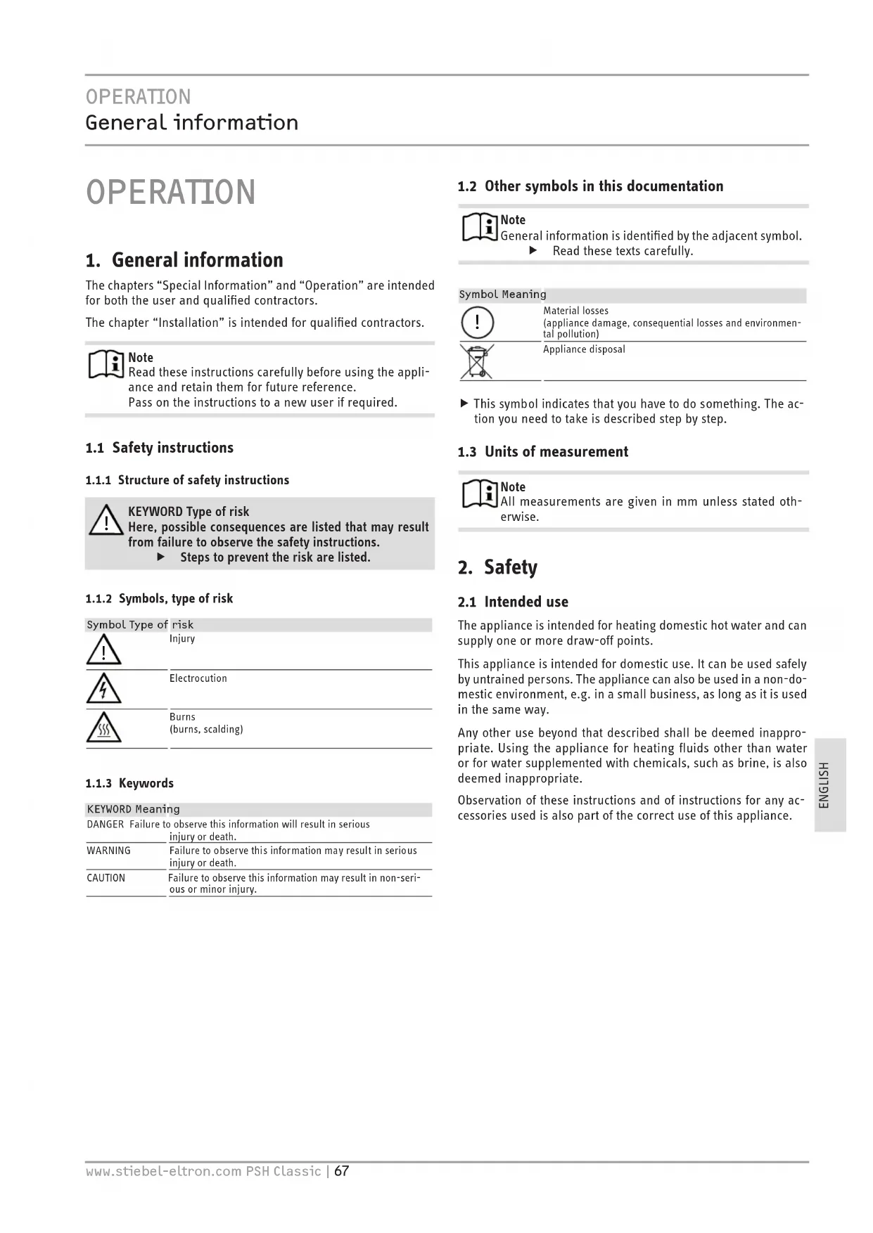
OPERATION
1. General information
The chapters “Special Information” and “Operation” are intended for both the user and qualified contractors.
The chapter "Installation" is intended for qualified contractors.

Note
Read these instructions carefully before using the appliance and retain them for future reference.
Pass on the instructions to a new user if required.
1.1 Safety instructions
1.1.1 Structure of safety instructions

KEYWORD Type of risk
Here, possible consequences are listed that may result from failure to observe the safety instructions.
▶ Steps to prevent the risk are listed.
1.1.2 Symbols, type of risk
Symbol Type of risk

Injury

Electrocution

Burns
(burns, scalding)
1.1.3 Keywords
KEYWORD Meaning
DANGER Failure to observe this information will result in serious injury or death.
WARNING Failure to observe this information may result in serious injury or death.
CAUTION Failure to observe this information may result in non-serious or minor injury.
1.2 Other symbols in this documentation

Note
General information is identified by the adjacent symbol.
▶ Read these texts carefully.
Symbol Meaning

Material losses
(appliance damage, consequential losses and environmental pollution)

Appliance disposal
This symbol indicates that you have to do something. The action you need to take is described step by step.
1.3 Units of measurement

Note
All measurements are given in mm unless stated otherwise.
2. Safety
2.1 Intended use
The appliance is intended for heating domestic hot water and can supply one or more draw-off points.
This appliance is intended for domestic use. It can be used safely by untrained persons. The appliance can also be used in a non-domestic environment, e.g. in a small business, as long as it is used in the same way.
Any other use beyond that described shall be deemed inappropriate. Using the appliance for heating fluids other than water or for water supplemented with chemicals, such as brine, is also deemed inappropriate.
Observation of these instructions and of instructions for any accessories used is also part of the correct use of this appliance.
2.2 General safety instructions

WARNING Burns
During operation, the tap and safety valve can reach temperatures in excess of 60 °C.
There is a risk of scalding at outlet temperatures in excess of 43^ C.

WARNING Injury
The appliance may be used by children aged 8 and older and persons with reduced physical, sensory or mental capabilities or a lack of experience and know-how, provided that they are supervised or they have been instructed on how to use the appliance safely and have understood the resulting risks. Children must never play with the appliance. Children must never clean the appliance or perform user maintenance unless they are supervised.

Material losses
The user should protect the water lines and the safety valve from frost.

Note
The appliance is pressurised. During the heat-up process, expansion water will drip from the safety valve.
▶ If water continues to drip when heating is completed, please inform your qualified contractor.
2.3 Test symbols
See type plate on the appliance.
3. Appliance description
The closed (pressure-tested) appliance heats DHW electrically. You can adjust the temperature using the temperature selector. Subject to the power supply, the water is automatically heated to the required temperature. You can read off the current DHW temperature at the temperature indicator.
The internal steel cylinder is coated with special "Co Pro" enamel and is equipped with a protective anode. The anode protects the internal cylinder from corrosion.
Frost protection
The appliance is also protected against frost by the temperature setting “*”, provided that the power supply is guaranteed. The appliance switches on in good time and heats the water. The appliance does not protect the water supply lines and the safety valve from frost.
4. Settings

Note
Only the contractor is permitted to remove the temperature selector.
The temperature is variably adjustable.
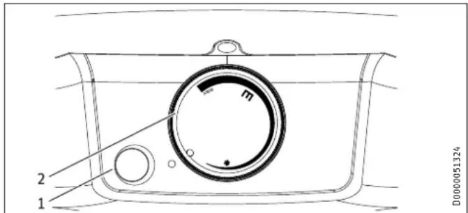
text_image
m 2 1 D00000513241 ON/OFF indicator
2 Temperature selector
* Frost protection
E Recommended energy saving position, low scaling, 60 °C
Max Maximum temperature setting, 70 °C
Depending on the system, the actual temperatures may vary from the set value.
ON/OFF indicator
The ON/OFF indicator illuminates when water is being heated.
Temperature indicator
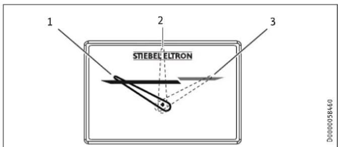
text_image
1 2 3 STIEBEL ELTRON D00000584601 Pointer position at approx. 30 °C
2 Pointer position at approx. 50 °C
3 Pointer position at approx. 70 °C
The current temperature is measured inside the cylinder, at the position of the temperature indicator (see chapter "Specification / Dimensions and connections").
4.1 Holiday and absence
▶ If the appliance is not to be used for a few days, set the temperature selector to a position between the frost protection and energy saving settings.
▶ If the appliance is not to be used for a longer period, set it to frost protection to conserve energy. If there is no risk of frost you may disconnect the appliance from the power supply.
For reasons of hygiene, heat up the content of the cylinder once to above 60 °C before initial use.
5. Cleaning, care and maintenance
▶ Have the electrical safety of the appliance and the function of the safety valve regularly checked by a qualified contractor.
▶ Have the protective anode initially checked by a qualified contractor after the first year. The qualified contractor will then determine the intervals at which repeat checks should be performed.
▶ Never use abrasive or corrosive cleaning agents. A damp cloth is sufficient for cleaning the appliance.
Scaling
▶ Almost every type of water will deposit limescale at high temperatures. This settles inside the appliance and affects both the performance and service life. The heating elements must therefore be descaled from time to time. A qualified contractor who knows the local water quality will tell you when the next service is due.
▶ Check the taps regularly. Limescale deposits at the tap outlets can be removed using commercially available descaling agents.
▶ Regularly activate the safety valve to prevent it from becoming blocked, e.g. by limescale deposits.
6. Troubleshooting
| Problem Cause Remedy | ||
| The water does not heat up and the ON/OFF indicator does not illuminate. | There is no power. | Check the fuses/MCBs in your fuse box/distribution panel. |
| The water does not heat up sufficiently and the ON/OFF indicator illuminates. | The temperature is set too low. | Select a higher temperature. |
| The appliance heats, for example, after large amounts of DHW have been drawn. | Wait until the ON/OFF indicator goes out. | |
| The flow rate is low. | The aerator in the tap or the shower head is scaled up or soiled. | Clean and/or descale the aerator or shower head. |
If you cannot remedy the fault, notify your qualified contractor. To facilitate and speed up your enquiry, please provide the numbers from the type plate (000000 and 0000-000000):
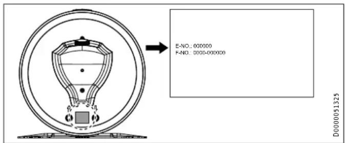
text_image
E-NO.: 000000 F-NO.: 5000-000000 D000001325INSTALLATION
7. Safety
Only a qualified contractor should carry out installation, commissioning, maintenance and repair of the appliance.
7.1 General safety instructions
We guarantee trouble-free function and operational reliability only if original accessories and spare parts intended for the appliance are used.
7.2 Instructions, standards and regulations

Note
Observe all applicable national and regional regulations and instructions.
8. Appliance description
8.1 Standard delivery
The following are delivered with the appliance:
- Safety valve
- Temperature indicator
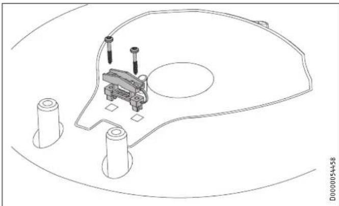
- Strain relief with 2 screws
9. Preparations
9.1 Installation site
The appliance is designed to be permanently wall mounted to a solid surface. Ensure the wall offers adequate load bearing capacity.
There should be a suitable drain near the appliance to drain off the expansion water.
Install the appliance vertically in a room free from the risk of frost and near the draw-off point.
It may not be fitted in a corner since the screws for fixing the appliance to the wall must remain accessible.
9.2 Fitting the wall mounting bracket

Note
Ensure that the temperature selector is accessible from the front.
The mounting bracket attached to the appliance has hook-in slots, which in most cases enables installation on the bolts that are already in place from previous appliances.
▶ Otherwise, transfer the dimensions for the holes to be drilled on the wall (see chapter “Specification / Dimensions and connections”).
▶ Drill the holes, if required, and secure the wall mounting bracket with screws and rawl plugs. Select fixing materials in accordance with the wall construction/condition.
▶ Hook the appliance with the wall mounting bracket on to the screws or bolts. Observe the dry weight of the appliance (see chapter "Specification / Data table") and, if necessary, ask another person to help.
▶ Align the appliance vertically.
9.3 Preparing the power cable
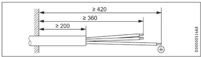
text_image
≥ 420 ≥ 360 ≥ 200 D000005146810. Installation
10.1 Water connection

Material losses
Carry out all water connection and installation work in accordance with regulations.
Operate the appliance only with pressure-tested taps.
▶ Thoroughly flush out the cold water line before connecting the appliance, so that no foreign matter gets into the water heater or safety valve.
▶ Connect the hydraulic connections with flat gaskets.
10.1.1 Permissible materials

Material losses
When using plastic pipework, observe the manufacturer's data and the chapter "Specification / Fault conditions".
Cold water line
Galvanised steel, stainless steel, copper and plastic are approved materials.
DHW line
Stainless steel, copper and plastic are approved materials.
10.1.2 Fitting the safety valve

Note
A pressure reducing valve must be installed in the cold water inlet if the water pressure is greater than 0.6 MPa.
The maximum permissible pressure must not be exceeded (see chapter "Specification / Data table").
▶ Install a type-tested safety valve in the cold water inlet line. Please note that, depending on the supply pressure, you may also need a pressure reducing valve.
▶ Size the drain so that water can drain off unimpeded when the safety valve is fully opened.
▶ Fit the discharge pipe of the safety valve with a constant downward slope and in a room free from the risk of frost.
▶ The safety valve discharge aperture must remain open to atmosphere.
Never install a stop fitting between the appliance and the safety valve.
10.2 Power supply

WARNING Electrocution
Carry out all electrical connection and installation work in accordance with relevant regulations.
Before any work on the appliance, ensure omnipolar disconnection from the power supply.

WARNING Electrocution
The connection to the power supply must be in the form of a permanent connection. Ensure the appliance can be separated from the power supply by an isolator that disconnects all poles with at least 3 mm contact separation.

WARNING Electrocution
Ensure that the appliance is earthed.

Material losses
Install a residual current device (RCD).

Material losses
Observe the type plate. The specified voltage must match the mains voltage.
▶ Undo the 2 screws on the bottom cap.
▶ Remove the lower cap. When doing so, take care with the connecting leads for the temperature controller and ON/OFF indicator, which are attached to the bottom cap.
natural_image
Technical line drawing of a mechanical component with three cylindrical parts and mounting holes (no text or symbols)▶ Fit the strain relief supplied.
▶ Install a power cable.
▶ Connect the power cable inside the appliance and secure it with the 2 screws.
▶ Secure the bottom cap with the 2 screws.
▶ Push on the temperature selector.
10.3 Installing the temperature indicator
▶ Press the temperature indicator into the opening until it clicks into place.
11. Commissioning
11.1 Initial start-up

Note
Fill the appliance with water prior to electrical connection. If you switch on the appliance while empty, the high limit safety cut-out will switch it off.
▶ Open the shut-off valve in the cold water inlet line.
▶ Open a draw-off point until the appliance has been filled with water and the pipework is free of air.
▶ Adjust the flow rate. For this, observe the maximum permissible flow rate with a fully opened tap (see chapter "Specification / Data table").
▶ Turn the temperature selector to maximum.
▶ Switch the mains power ON.
▶ Check the appliance function. Ensure that the temperature controller switches off.
▶ Check that the safety valve is working.
11.1.1 Appliance handover
Explain the function of the appliance and safety valve to users and familiarise them with their operation.
▶ Make the user aware of potential dangers, especially the risk of scalding.
▶ Hand over these instructions.
11.2 Recommissioning
See chapter "Commissioning".
12. Shutdown
▶ Disconnect the appliance from the mains at the MCB/fuse in the fuse box.
- Drain the appliance. See chapter "Maintenance / Draining the appliance".
13. Troubleshooting

Note
At temperatures below -15^ the high limit safety cut-out may respond. The appliance may be subjected to these temperatures during storage or transport.
| Fault Cause Remedy | ||
| The water does not heat up and the ON/OFF indicator does not illuminate. | The high limit safety cut-out has responded because the controller is faulty. | Remedy the cause of the fault. Replace the controller. |
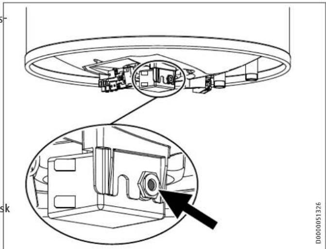
| The high limit safety cut-out has responded because the temperature has fallen below -15 °C. | Press the reset button (see diagram). | |
| The water does not heat up and the ON/OFF indicator illuminates. | The heating element is faulty. | Replace the heating element. |
| The water does not heat up sufficiently and the ON/OFF indicator illuminates. | The temperature controller is faulty. | Replace the temperature controller. |
| The heat-up time is very long and the ON/OFF indicator illuminates. | The heating element is scaled up. | Descale the heating element. |
| The safety valve drips when heating is switched off. | The valve seat is contaminated. | Clean the valve seat. |
| Water pressure is too | high. | Install a pressure reducing valve. |
Reset button, high limit safety cut-out
natural_image
Technical line drawing of a mechanical component with an inset close-up showing internal structure (no text or symbols)14. Maintenance

WARNING Electrocution
Carry out all electrical connection and installation work in accordance with relevant regulations.
Before any work on the appliance, disconnect all poles of the appliance from the power supply.
If you need to drain the appliance, observe chapter "Draining the appliance".
14.1 Checking the safety valve
▶ Check the safety valve regularly.
14.2 Draining the appliance

WARNING Burns
Hot water may escape during draining.
If the appliance needs to be drained for maintenance or to protect the whole installation when there is a risk of frost, proceed as follows:
▶ Close the shut-off valve in the cold water inlet line.
▶ Open the DHW valves of all draw-off points until the appliance is fully drained.
▶ Drain any residual water from the safety valve.
14.3 Checking / replacing the protective anode
▶ Check the protective anode after the first year of use and replace if necessary.
▶ Next, decide the time intervals at which further checks should be carried out.
14.4 Descaling
▶ Remove loose scale deposits from the water heater.
▶ If necessary, descale the inner cylinder with commercially available descaling agents.
▶ Descale the flange only after removal.
▶ Never treat the cylinder surface or the protective anode with descaling agents.
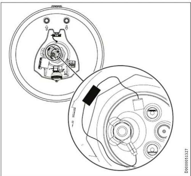
14.5 Anti-corrosion protection
Ensure that while carrying out maintenance work the anti-corrosion protection (560 Ω) is not damaged or removed. Reinsert the anti-corrosion protection correctly after replacement.
natural_image
Technical line drawing of a mechanical component with two views: top shows internal components, bottom shows external assembly (no text or symbols)14.6 Replacing the combined controller/limiter
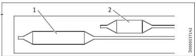
text_image
1 2 D0000371421 Controller sensor
2 Limiter sensor
▶ Insert the controller sensor and the limiter sensor into the sensor well as far as they will go.
15. Specification
15.1 Dimensions and connections
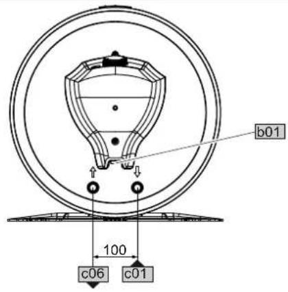
text_image
b01 100 c06 c01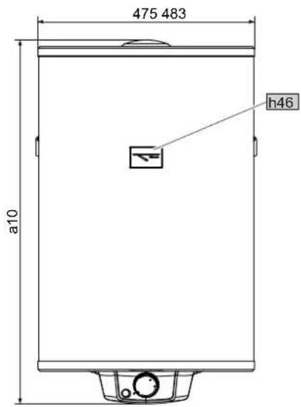
text_image
475 483 a10 h46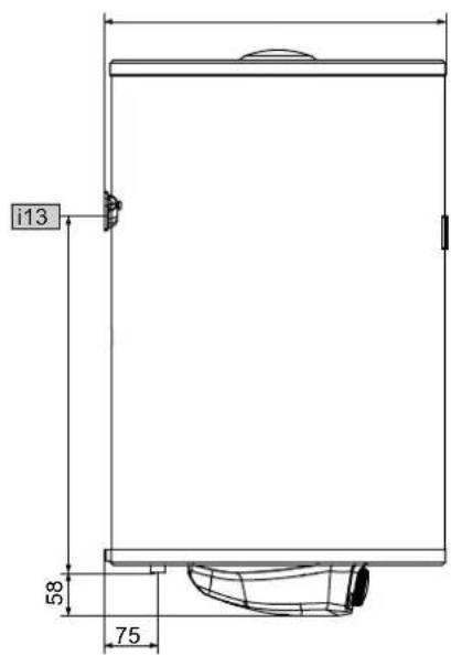
text_image
i13 58 75D0000051318
| PSH 50 | Classic | PSH 80 Classic | PSH 100 Classic | PSH 120 Classic | PSH 150 Classic | PSH 200 Classic | |||
| a10 | Appliance | Height | mm | 609 | 810 | 964 | 1117 | 1349 | 1704 |
| b01 | Entry electrical cables | ||||||||
| c01 | Cold water inlet | Male thread | G 1/2 A | G 1/2 A | G 1/2 A | G 1/2 A | G 1/2 A | G 1/2 A | |
| c06 | DHW outlet | Male thread | G 1/2 A | G 1/2 A | G 1/2 A | G 1/2 A | G 1/2 A | G 1/2 A | |
| h46 | Temperature indicator | ||||||||
| i13 | Wall mounting bracket | Height | mm | 450 | 520 | 790 | 825 | 1060 | 1360 |
Wall mounting bracket
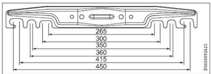
text_image
265 300 350 360 415 450 D000009262315.2 Wiring diagram
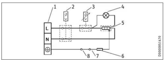
text_image
1 2 3 4 5 L N 8 7 6 D00000514701 Terminal
2 High limit safety cut-out
3 Temperature controller
4 ON/OFF indicator
5 Heating element
6 Electrical resistance 560 ohm
7 Anode
8 Cylinder
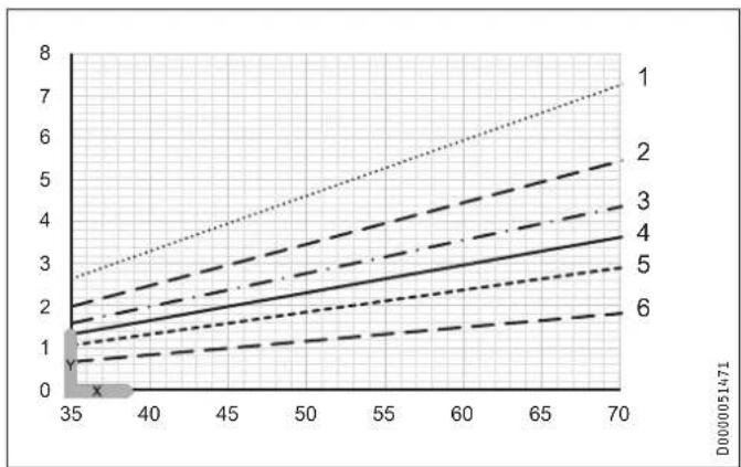
15.3 Heat-up diagrams
The heat-up time depends on the cylinder capacity, cold water inlet temperature and heating output.
Graph assumes 15 °C cold water inlet temperature:
line
| x | y | |----|------| | 35 | 0.5 | | 40 | 1.0 | | 45 | 1.5 | | 50 | 2.0 | | 55 | 2.5 | | 60 | 3.0 | | 65 | 3.5 | | 70 | 4.0 |X Temperature setting [°C]
Y Heat-up time [h]
1 200 |
2 150 |
3 120 |
4 100 |
5 801
6 501
15.4 Fault conditions
In the event of a fault, temperatures of up to 95 °C at 0.6 MPa can occur.
15.5 Details on energy consumption
Product datasheet: Conventional water heaters to regulation (EU) no. 814/2013
| PSH 50 | Classic | PSH 80 Classic | PSH 100 Classic | PSH 120 Classic | PSH 150 Classic | PSH 200 Classic | |
| 235960 235961 235962 235963 235964 235965 | |||||||
| Manufacturer STIEBEL | ELTRON | STIEBELELTRON | STIEBELELTRON | STIEBELELTRON | STIEBELELTRON | STIEBELELTRON | |
| Load profile | M | M | L | L | L | XL | |
| Energy efficiency class | C | C | C | C | C | C | |
| Energy conversion efficiency | % | 38 | 37 | 38 | 38 | 37 | 38 |
| Annual power consumption | kWh | 1353 | 1386 | 2694 | 2723 | 2766 | 4406 |
| Default temperature setting | °C | 60 | 60 | 60 | 60 | 60 | 60 |
| Sound power level | dB(A) | 15 | 15 | 15 | 15 | 15 | 15 |
| Option for exclusive operation during off-peak periods | - | - | - | - | - | - | |
| Smart function | - | - | - | - | - | - | |
| Cylinder capacity | | | 53 | 80 | 100 | 120 | 150 | 192 |
| Mixed water volume at 40 °C | | | 82 | 125 | 168 | 219 | 270 | 347 |
| Daily power consumption | kWh | 6.253 | 6.448 | 12.452 | 12.620 | 12.876 | 20.363 |
15.6 Data table
| PSH 50 | Classic | PSH 80 Classic | PSH 100 Classic | PSH 120 Classic | PSH 150 Classic | PSH 200 Classic | |
| 235960 235961 235962 235963 235964 235965 | |||||||
| Hydraulic data | |||||||
| Nominal capacity | I | 53 | 80 | 100 | 120 | 150 | 192 |
| Mixed water volume at 40 °C | I | 82 | 125 | 168 | 219 | 270 | 347 |
| Electrical data | |||||||
| Connected load ~ 230 V | kW | 1.8 | 1.8 | 1.8 | 1.8 | 1.8 | 1.8 |
| Rated voltage | V | 220-240 | 220-240 | 220-240 | 220-240 | 220-240 | 220-240 |
| Phases | 1/N/PE | 1/N/PE | 1/N/PE | 1/N/PE | 1/N/PE | 1/N/PE | |
| Frequency | Hz | 50/60 | 50/60 | 50/60 | 50/60 | 50/60 | 50/60 |
| Single circuit operating mode | X | X | X | X | X | X | |
| Heat-up time from 15°C to 65°C | h | 1.81 | 2.64 | 3.3 | 3.96 | 4.94 | 6.59 |
| Application limits | |||||||
| Temperature setting range | °C | 30-70 | 30-70 | 30-70 | 30-70 | 30-70 | 30-70 |
| Max. permissible pressure | MPa | 0.6 | 0.6 | 0.6 | 0.6 | 0.6 | 0.6 |
| Max. permissible temperature | °C | 95 | 95 | 95 | 95 | 95 | 95 |
| Max. flow rate | l/min | 23.5 | 23.5 | 23.5 | 23.5 | 23.5 | 23.5 |
| Min./max. conductivity, drinking water | μS/cm | 100-1500 | 100-1500 | 100-1500 | 100-1500 | 100-1500 | 100-1500 |
| Energy data | |||||||
| Standby energy consumption/24 h at 65 °C | kWh | 0.96 | 1.22 | 1.47 | 1.73 | 2.05 | 2.45 |
| Energy efficiency class | C | C | C | C | C | C | |
| Versions | |||||||
| Sealed unvented type | X | X | X | X | X | X | |
| IP rating | IP24 | IP24 | IP24 | IP24 | IP24 | IP24 | |
| Frost protection setting | °C | 7 | 7 | 7 | 7 | 7 | 7 |
| Colour | White | White | White | White | White | White | |
| Dimensions | |||||||
| Height | mm | 609 | 810 | 964 | 1117 | 1349 | 1704 |
| Depth | mm | 483 | 483 | 483 | 483 | 483 | 483 |
| Diameter | mm | 475 | 475 | 475 | 475 | 475 | 475 |
| Weights | |||||||
| Weight, full | kg | 72 | 104 | 128 | 152 | 189 | 242 |
| Weight, empty | kg | 19 | 24 | 28 | 32 | 39 | 50 |
Guarantee
The guarantee conditions of our German companies do not apply to appliances acquired outside of Germany. In countries where our subsidiaries sell our products a guarantee can only be issued by those subsidiaries. Such guarantee is only granted if the subsidiary has issued its own terms of guarantee. No other guarantee will be granted.
We shall not provide any guarantee for appliances acquired in countries where we have no subsidiary to sell our products. This will not affect warranties issued by any importers.
Environment and recycling
We would ask you to help protect the environment. After use, dispose of the various materials in accordance with national regulations.
ZVLÁŠTNÍ POKYNY
OBSLUHA
- Obecné pokyny 77
natural_image
Technical line drawing of a mechanical component with three cylindrical parts and mounting holes (no text or symbols)natural_image
Technical diagram showing a mechanical assembly with an inset close-up of a component, no visible text or symbols.14. Údržba

VÝSTRAHA elektrický proud
natural_image
Technical diagram of a mechanical device showing internal components and assembly (no text or labels)natural_image
Technical line drawing of a mechanical component with three cylindrical parts and mounting holes (no text or symbols)natural_image
Technical line drawing of a mechanical assembly with an inset close-up showing internal components (no text or symbols)14. Karbantartás

natural_image
Technical line drawing of a mechanical component with two views (top and side), no visible text or symbolsnatural_image
Technical line drawing of a mechanical component with three cylindrical parts and mounting holes (no text or symbols)natural_image
Technical line drawing of a mechanical component with an inset close-up showing internal structure (no text or symbols)natural_image
Technical line drawing of a mechanical device with two views: top shows internal components, bottom shows external wiring (no text or symbols)natural_image
Technical line drawing of a mechanical component with three cylindrical parts and mounting holes (no text or symbols)natural_image
Technical line drawing of a mechanical component with an inset close-up showing internal structure (no text or symbols)natural_image
Technical line drawing of a mechanical component with two views (top and side), no visible text or symbolsnatural_image
Technical line drawing of a mechanical component with three cylindrical parts and mounting holes (no text or symbols)natural_image
Technical diagram showing a mechanical assembly with an inset close-up of a component detail (no text or symbols present)14. Apkope

BRĪDINĀJUMS Strāvas trieciens
natural_image
Technical line drawing of a mechanical device with two views: top shows internal components, bottom shows external wiring (no text or symbols)www.stiebel-eltron.com.au
Austria
STIEBEL ELTRON Ges.m.b.H.
Plant C3, XEDA International Industry City
Xiqing Economic Development Area
300385 Tianjin
Tel. 022 8396 2077 | Fax 022 8396 2075
info@stiebeleltron.cn
www.stiebeleltron.cn
Czech Republic
STIEBEL ELTRON spol. s r.o.
61 Barrys Point Road | Auckland 0622
Tel. +64 9486 2221
info@stiebel-eltron.co.nz
www.stiebel-eltron.co.nz
Poland
STIEBEL ELTRON Polska Sp. z 0.0.
Urzhumskaya street 4,
building 2 | 129343 Moscow
Tel. +7 495 125 0 125
info@stiebel-eltron.ru
www.stiebel-eltron.ru
Slovakia
STIEBEL ELTRON Slovakia, s.r.o.
Hlavná 1 | 058 01 Poprad
Tel. 052 7127-125 | Fax 052 7127-148
info@stiebel-eltron.sk
www.stiebel-eltron.sk
Switzerland
STIEBEL ELTRON AG
Industrie West
Gass 8 | 5242 Lupfig
Tel. 056 4640-500 | Fax 056 4640-501
info@stiebel-eltron.ch
www.stiebel-eltron.ch
Thailand
STIEBEL ELTRON Asia Ltd.
469 Moo 2 Tambol Klong-Jik
Amphur Bangpa-In | 13160 Ayutthaya
Tel. 035 220088 | Fax 035 221188
info@stiebeleltronasia.com
www.stiebeleltronasia.com
United Kingdom and Ireland
STIEBEL ELTRON UK Ltd.
Unit 12 Stadium Court
Stadium Road | CH62 3RP Bromborough
Tel. 0151 346-2300 | Fax 0151 334-2913
info@stiebel-eltron.co.uk
www.stiebel-eltron.co.uk
United States of America
STIEBEL ELTRON, Inc.
17 West Street | 01088 West Hatfield MA
Tel. 0413 247-3380 | Fax 0413 247-3369
info@stiebel-eltron-usa.com
www.stiebel-eltron-usa.com

text_image
4017213213185Irrtum und technische Änderungen vorbehalten! | Subject to errors and technical changes! | Sous réserve d'erreurs et de modifications techniques! | Onder voorbehoud van vergissingen en technische wijzigingen! | Salvo error o modificación técnica! | Excepto erro ou alteração técnica | Zastrzeżone zmiany techniczne i ewentualne błędy | Omyly a technické zmény jsou vyhrazeny! | A muszaki változtalások és têvedések jogát fenntartjuk! | Otcutствие ошибok ne гарантируется. Возможны технические изменения. | Chyby a technické zmény sű vyhradené! Stand 9646