DHC Trend - Boiler STIEBEL ELTRON - Free user manual and instructions
Find the device manual for free DHC Trend STIEBEL ELTRON in PDF.
User questions about DHC Trend STIEBEL ELTRON
0 question about this device. Answer the ones you know or ask your own.
Ask a new question about this device
Download the instructions for your Boiler in PDF format for free! Find your manual DHC Trend - STIEBEL ELTRON and take your electronic device back in hand. On this page are published all the documents necessary for the use of your device. DHC Trend by STIEBEL ELTRON.
USER MANUAL DHC Trend STIEBEL ELTRON
natural_image
Line drawing of a rectangular device with a vertical screen and a horizontal line at the bottom (no text or symbols)
Certified to ANSI/UL Std. 499
Conforms to CAN/CSA Std. C22.2 No. 64
Tested and certified by WQA to NSF/ANSI/CAN 372 for lead free compliance.
1.1 Safety instructions 5
1.2 Other symbols in this documentation 5
1.3 Units of measurement 5
- Safety 5
2.1 Intended use 5
2.2 General safety instructions 5
2.3 Test symbols 6
2.4 Licenses / certificates 6
-
Register your product 6
-
Water heater description 7
4.1 Recommended settings 7
-
Cleaning, care and maintenance 7
-
Troubleshooting 7
INSTALLATION
- Safety 8
7.1 General safety instructions 8
7.2 Instructions, standards and regulations 8
- Water heater description 8
8.1 Standard delivery 8
- Preparation
9.1 Installation site 8
9.2 Minimum clearances 9
- Installation 9
10.1 Standard wall-mounted installation 9
10.2 Water connections 9
10.3 Aerator installation at connected faucet 10
10.4 Electrical connection 10
10.5 Electrical connection with short power cable 11
10.6 Wiring block 12
- Commissioning 12
11.1 Temperature setting via jumper slot ____ 12
11.2 Changing power output via jumper slot 12
11.3 Initial start-up 12
11.4 Operation with preheated water 13
11.5 Recommissioning 13
-
Water heater shutdown 13
-
Service information 13
-
Maintenance 14
14.1 Draining the water heater 14
14.2 Cleaning the filter screen 14
-
Troubleshooting 15
-
Specification 16
16.1 Dimensions 16
16.2 Wiring diagrams 16
16.3 Hot water output 17
16.4 Application areas/conversion table 17
16.5 Fault conditions 17
16.6 Data tables 18
-
Spare parts 20
-
Warranty 21
QUICK START GUIDE
Before turning on power to the water heater, you MUST flush all air out of the system, then engage the AE3 safety switch. The unit will NOT operate until the AE3 safety switch has been engaged.
1 Mount the unit to the wall (see section 10.1, "Standard wall-mounted installation", pg. 9).
2 Hook up water connections (see section 10.2, "Water connections", pg. 9).
3 Hook up electrical connections, but keep circuit breaker off. (See section 10.4, “Electrical connection”, pg. 10)
on
① ≥ 3 min.
D0000053277
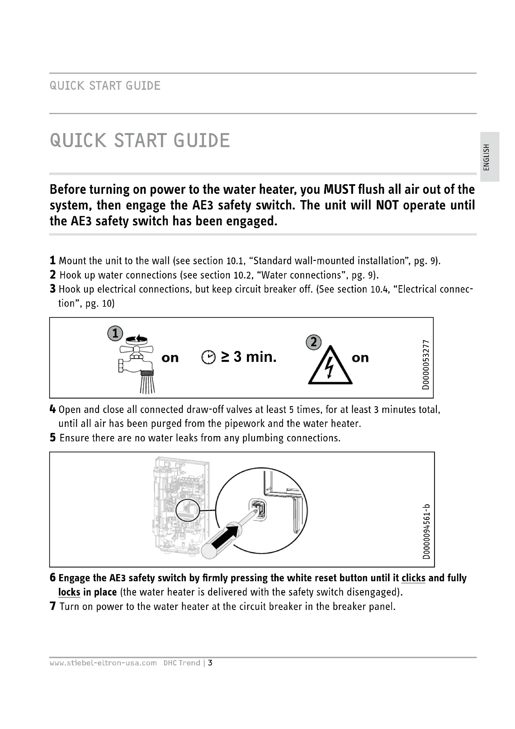
4 Open and close all connected draw-off valves at least 5 times, for at least 3 minutes total, until all air has been purged from the pipework and the water heater.
5 Ensure there are no water leaks from any plumbing connections.
natural_image
Diagram showing a computer interface with an inset close-up of a plug inserted into a socket (no text or symbols present)D0000094561-b
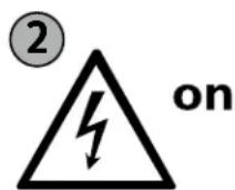
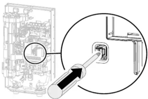
6 Engage the AE3 safety switch by firmly pressing the white reset button until it clicks and fully locks in place (the water heater is delivered with the safety switch disengaged).
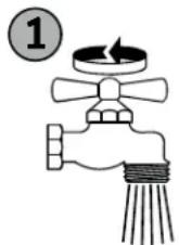
7 Turn on power to the water heater at the circuit breaker in the breaker panel.
SPECIAL INFORMATION
- Read this entire manual. Failure to follow all the guides, instructions and rules could cause personal injury or property damage. Improper installation, adjustment, alteration, service and use of this unit can result in serious injury.
- This unit must be installed by a licensed electrician and plumber. The installation must comply with all national, state and local plumbing and electric codes. Proper installation is the responsibility of the installer. Failure to comply with the installation and operating instructions or improper use voids the warranty.
- Save these instructions for future reference. The installer should leave these instructions with the consumer.
- If you have any questions regarding the installation, use or operation of this water heater, or if you need any additional installation manuals, please call our technical service line at 800.582.8423 (USA and Canada only). If you are calling from outside the USA or Canada, please call USA 413.247.3380 and we will refer you to a qualified Stiebel Eltron service representative in your area.
- The water heater is suitable for supplying a shower in many climates (shower operation). If the water heater is also or exclusively used for shower operation, the qualified contractor must adjust the temperature setting range to 122 °F (50 °C) or less using the internal anti-scalding protection on the water heater. When using preheated water, it must be ensured that the inlet temperature does not exceed 131 °F (55 °C).
- The specified voltage must match the power supply. See the type plate on the right-hand side of the water heater for full information.
- Ensure the water heater can be separated from the power supply by a circuit breaker that disconnects all poles with at least 1/8" (3 mm) contact separation.
- CAUTION: DO NOT INSTALL IN A BATH ENCLOSURE OR SHOWER STALL.
DO NOT CONNECT TO A SALT-REGENERATED WATER SOFTENER OR A SALT-WATER WATER SUPPLY. FOR USE ON AN INDIVIDUAL BRANCH CIRCUIT ONLY. CAUTION: CONNECT ONLY TO A CIRCUIT PROTECTED BY A CLASS A GROUND FAULT INTERRUPTER USE BONDING CONDUCTOR IN ACCORDANCE WITH THE CANADIAN ELECTRICAL CODE, PART I
- The water heater must be properly grounded. See section 16.2, "Wiring diagrams," pg. 16.
- The water heater must be permanently connected to fixed wiring. For use on an individual branch circuit only. See section 16.2, "Wiring diagrams," pg. 16.
- Secure the water heater as described in chapter 10, "Installation", pg. 9.
- Observe the minimum permissible water supply pressure of 26.1 psi (1.8 bar). See section 16.6, “Data tables,” pg. 18.
- Observe the maximum permissible water supply pressure of 145 psi (10 bar). See section 16.6, "Data tables," pg. 18.
- Drain the water heater as described in section 14.1, "Draining the water heater", pg. 14.
OPERATION
1. General information
The chapters “Special information” and “Operation” are intended for both users and qualified contractors.
The chapter "Installation" is intended for qualified contractors.

Note
Read these instructions carefully before using the water heater and retain them for future reference. Pass on the instructions to a new user if required.
1.1 Safety instructions
1.1.1 Structure of safety instructions

KEYWORD Type of risk Here, possible consequences are listed that may result from failure to observe the safety instructions.
▶ Steps to prevent the risk are listed.
1.1.2 Symbols, type of risk
Symbol Type of risk

Injury

Electrocution

Burns (burns, scalding)
1.1.3 Keywords
KEYWORD Meaning
DANGER Failure to observe this information will result in serious injury or death.
| WARNING | Failure to observe this information may result in serious injury or death. |
| CAUTION | Failure to observe this information may result in non-serious or minor injury. |
1.2 Other symbols in this documentation

Note
General information is identified by the adjacent symbol.
▶ Read these texts carefully.
Symbol
Meaning

Material losses
(water heater damage, material losses, and installation site damage)
This symbol indicates that you have to do something. The action you need to take is described step by step.
1.3 Units of measurement

Note
All measurements are given in inches (millimeters) unless otherwise stated.
2. Safety
2.1 Intended use
The DHC Trend is suitable for heating domestic hot water or for reheating preheated water. The water heater can supply one or more draw-off points such as hand washing, kitchen, or utility sinks.
Examples:
- Restroom sinks in commercial/industrial facilities and homes
- Kitchen areas in commercial /industrial facilities and homes
- Special uses in photo developing shops, laboratories etc.
Water will not be reheated if the maximum inlet temperature for reheating is exceeded.
The water heater is intended for domestic use. It can be used safely by untrained persons. The water heater can also be used in non-domestic environments, e.g. in small businesses, as long as it is used in the same way.
Any other use beyond that described shall be deemed inappropriate. Observation of these instructions and of the instructions for any accessories used is also part of the correct use of this water heater.
2.2 General safety instructions

DANGER: Burns
Water temperatures over 125^ F ( 52^ C) can cause severe burns instantly or death from scalding. A hot water scalding potential exists if the thermostat on the water heater is set too high. Households with small children, disabled or elderly persons may require that the thermostat be set at 110^ F ( 43^ C) or lower to prevent possible injury from hot water.

CAUTION: Burns
If operating with preheated water, e.g. from a solar thermal system, the DHW temperature may vary from the selected set temperature.

CAUTION: Burns
During operation, the tap can reach temperatures up to 149 °F (65 °C).
There is a risk of scalding at outlet temperatures in excess of 110 °F (43 °C).

DANGER: Injury
Please read and follow these instructions. Failure to follow these instructions could result in serious personal injury or death.

CAUTION: DO NOT INSTALL IN A BATH ENCLOSURE OR SHOWER STALL. DO NOT CONNECT TO A
SALT-REGENERATED WATER SOFTENER OR A WATER SUPPLY OF SALT WATER.
FOR USE ON AN INDIVIDUAL BRANCH CIRCUIT ONLY.
CAUTION: CONNECT ONLY TO A CIRCUIT PROTECTED BY A CLASS A GROUND FAULT INTERRUPTER
USE BONDING CONDUCTOR IN ACCORDANCE WITH THE CANADIAN ELECTRICAL CODE, PART I

DANGER: Electrocution
Before proceeding with any installation, adjustment, alteration, or service of this appliance, all circuit breakers and disconnect switches servicing the appliance must be turned off. Failure to do so could result in serious personal injury or death.

DANGER: Electrocution
Never remove the water heater's cover unless the electricity servicing the water heater is turned off. Failure to do so could result in personal injury or death.

WARNING Electrocution
The connection to the power supply is only permissible as a permanent connection in conjunction with a 34 " Romex clamp. Ensure the water heater can be separated from the power supply by an isolator that disconnects all poles with at least 1/8'' (3 mm) contact separation.

DAMAGE TO THE WATER HEATER AND THE ENVIRONMENT:
The water heater must be installed by a licensed electrician and plumber. The installation must comply with all national, state and local plumbing and electric codes.
Service of the water heater must be performed by qualified service technicians.

DAMAGE TO THE WATER HEATER AND THE ENVIRONMENT:
Supply this appliance only from a grounded system. A green terminal (or a wire connector marked "G", "GR", "GROUND", OR "GROUNDING") is provided for wiring the appliance. To reduce the risk of electric shock, connect this terminal or connector to the grounding terminal of the electric service or supply panel with a continuous copper wire in accordance with the electrical installation code.

WARNING: Injury
Where children or persons with limited physical, sensory or mental capabilities are to be allowed to control this water heater, ensure that this will only happen under supervision or after appropriate instructions by a person responsible for their safety. Children should be supervised to ensure that they never play with the water heater.
Where children or persons with limited physical, sensory or mental abilities are allowed to use this water heater, we recommend asking the qualified contractor to set a permanent "Internal anti-scalding protection" temperature limit. See section 11.1, "Temperature setting via jumper slot," pg. 12.

Material losses
The user should protect the water heater against frost.
2.3 Test symbols
See type plate on the water heater.
2.4 Licenses / certificates
- UL (USA) Std. 499
- CSA (Canada) Std. C22.2 No. 64
3. Register your product

You must register this product within 90 days of purchase on our web site in order to activate the standard warranty. Go to our web site at www.stiebel-eltron-usa.com and click on "Register Your Product."
Before beginning the registration process, we suggest that you gather the necessary information which will be as follows:
Type, Example: DHC 4/6-2 Trend (from the label that is on the unit)
Number listed after "No."
Place of Purchase
Purchase Date
First & Last Name
Email address
Physical Address
Phone Number
Installation Date
If you have any questions concerning the registration process or warranty, please contact Stiebel Eltron USA directly at 800.582.8423.
4. Water heater description
The water heater switches on automatically as soon as a hot water valve at the tap is opened. When you close the tap, the water heater switches off automatically.
From the activation flow rate, the control unit regulates the correct heating output, subject to the temperature selected internally via jumper by a contractor during installation, and the current cold incoming water temperature.
If the water heater is operated with preheated water and the inlet temperature exceeds the chosen set temperature, the water is not heated further.
Fixed Domestic Hot Water (DHW) temperature
The water heater heats water as it flows through the unit.
The fixed DHW outlet temperature can be adjusted by a contractor via jumper during installation. The factory default value is 100 °F (38 °C). Other selectable values include: 110 °F (43 °C), 122 °F (50 °C), 140 °F (60 °C).
Heating system
The Direct Coil ^™ heating system is comprised of a pressure-tested, glass-reinforced polyamide heating chamber with a nichrome wire direct heating coil. It is suitable for hard and soft water areas and is largely insusceptible to scale build-up. The Direct Coil ^™ heating system ensures rapid and efficient DHW production.

Note
The water heater is equipped with an air detector that largely prevents damage to the heating system. If, during operation, air is drawn into the water heater, the water heater shuts down the heating output for one minute to protect the heating system.
4.1 Recommended settings
The DHC Trend electric tankless water heater offers maximum convenience and accuracy when providing DHW. If you do need to operate the water heater with a thermostatic valve, we recommend adjusting the required set temperature on the thermostatic valve.
4.1.1 Following an interruption to the water supply

Material losses
To ensure that the direct coil heating system is not damaged following an interruption to the water supply, the water heater must be restarted by taking the following steps.
▶ Disconnect the water heater from the power supply by turning off the connected circuit breaker.
▶ Open and close all connected draw-off valves at least 5 times, for at least 3 minutes total, until all air has been purged from the pipework and the water heater.
▶ Switch the power back at the circuit breaker back ON.
5. Cleaning, care and maintenance
▶ Never use abrasive or corrosive cleaning agents. A damp cloth is sufficient for cleaning the water heater.
▶ Check the taps regularly. Limescale deposits at the tap outlets can be removed using commercially available descaling agents.
6. Troubleshooting
| Problem Cause Solution | ||
| The water heater will not start despite the faucet being fully open | There is no power | Check to ensure circuit breaker in breaker panel hasn't tripped. Reset if necessary |
| The white AE3 safety switch has not been engaged during initial startup. Activate if necessary (See section 11.3.1, “Initial AE3 safety switch activation,” pg. 13). If the AE3 switch has tripped after initial installation, contact a qualified contractor to fix the cause | ||
| The aerator in the tap or the shower head is scaled up or dirty | Clean and/or descale the aerator or shower head | |
| The water supply has | been interrupted | Vent the water heater and the cold water inlet line |
| When hot water is being drawn off, cold water flows for a short period | The air detector detects air in the water. It switches off the heating output briefly | The water heater restarts automatically after 1 minute |
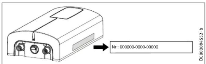
If you cannot solve the problem, contact your qualified contractor. To facilitate and speed up your inquiry, please provide the serial number from the type plate (000000-0000-000000). For live technical assistance, please contact us at 800.582.8423. Alternatively, you may email us at info@stiebel-eltron-usa.com
text_image
Nr.: 000000-0000-00000 D0000094552-bINSTALLATION
7. Safety
Only a qualified contractor should carry out installation, commissioning, maintenance and repair of the water heater.
7.1 General safety instructions
We guarantee trouble-free function and operational reliability only if original accessories and spare parts intended for the water heater are used.

Material losses
Observe the maximum inlet temperature. Higher temperatures may damage the water heater. You can limit the maximum inlet temperature by installing a central thermostatic valve.

WARNING Electrocution
This water heater contains capacitors which are discharged when disconnected from the power supply. The capacitor discharge voltage may briefly exceed 60 V DC.
7.2 Instructions, standards and regulations

Note
Observe all applicable national and regional regulations and instructions.
- The electrical resistivity of the water must not fall below that stated on the type plate. In a linked water network, factor in the lowest electrical resistivity of the water. Your water supply utility will advise you of the electrical resistivity or conductivity of the water in your area.
8. Water heater description
8.1 Standard delivery
The following are delivered with the water heater:
- Filter screen, factory installed in cold water inlet
- Jumper for temperature selection, attached
- Jumper for power output switching, attached
- Jumper, spare, attached
- 2 x mounting screws
- 2 x wall anchors
- 0.5 gpm (1.9 l/min) flow-reducer/aerator [DHC 3/3.5-1 Trend only]. See section 10.3, "Aerator installation at connected faucet," pg. 10, for more information.
- 2 x 0.5 gpm (1.9 l/min) and 1 x 1.0 gpm (3.8 l/min) flow-reducer/aerators [DHC 4/6-2 Trend only]. See section 10.3, "Aerator installation at connected faucet," pg. 10, for more information.
9. Preparation
9.1 Installation site

Material losses
Install the water heater in a room that is free from the risk of frost.
▶ Install DHC Trend in a frost free area. If frost may occur, remove the unit before freezing temperatures set in.
▶ Always install the water heater vertically with plumbing fittings pointing downward. Install the water heater near the draw-off point to minimize pipe runs and thermal losses.
▶ Taps: Do not use open vented or non-pressurized taps.
The water heater is suitable for under-sink and over-sink installation.
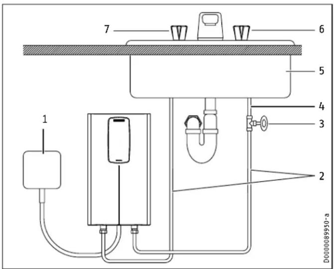
Typical under-sink installation
text_image
1 2 3 4 5 6 7 D0000089950-a1 Electrical junction box
2 1/2" water supply line for faucet installation
3 Shut-off valve
4 Cold water supply
5 Sink
6 Cold valve (right)
7 Hot valve (left)

Note
▶ Install the water heater flush to the wall. The wall must have sufficient load bearing capacity.
9.2 Minimum clearances
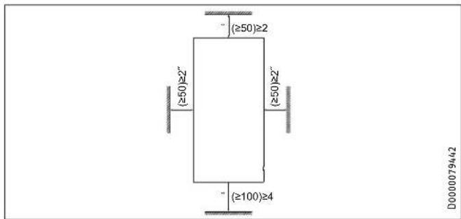
text_image
(≥50)≥2 (≥50)≥2" (≥50)≥2" (≥100)≥4 D0000079442- Maintain the minimum clearances to ensure trouble-free operation of the water heater and facilitate maintenance work.
10. Installation
| Factory default settings DHC | 3/3.5-1 Trend | DHC 4/6-2 Trend | DHC 8/10-2 Trend | DHC 12/15-2 Trend | |
| Internal temperature setting, °F (°C) | 100 (38) | 100 (38) | 100 (38) | 100 (38) | |
| Power output | @ 120 V | 3.5 kW | - | - | - |
| @ 208 V | - | 4.5 kW | 7.2 kW | 10.8 kW | |
| @ 240 V | - | 6.0 kW | 9.6 kW | 14.4 kW | |
10.1 Standard wall-mounted installation
10.1.1 Preparing the power cable
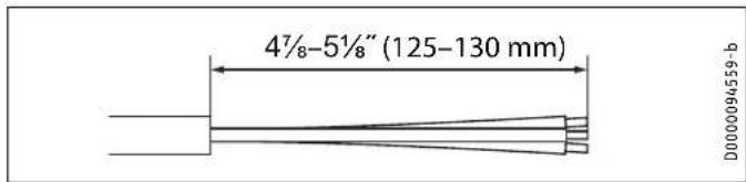
text_image
4½-5½" (125-130 mm) D0000094559-b▶ Prepare the power cable.
10.1.2 Mounting instructions
▶ Install DHC Trend as close as possible to the hot water draw-off point, for example, directly underneath the sink.
▶ Install DHC Trend in a frost free area. If frost may occur, remove unit before freezing temperatures set in.
▶ Observe minimum clearances on all sides to ensure unobstructed servicing if necessary.
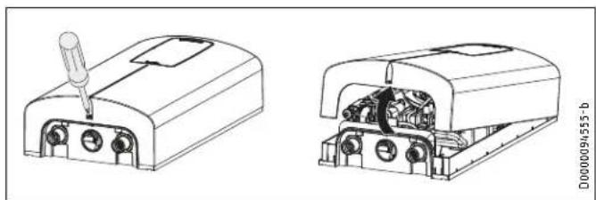
▶ Remove plastic cover by loosening the screw on the bottom. Lift cover off from the bottom.
natural_image
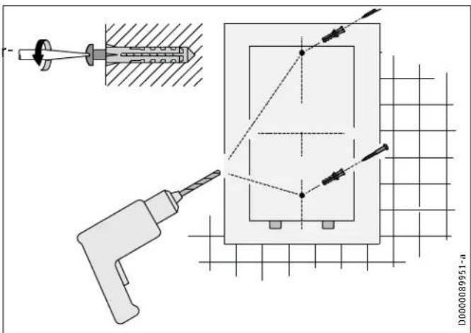
Technical line drawings of two electronic components with internal wiring (no text or symbols)- Mark the 2 drill holes, referencing their position using the water heater rear panel as a guide.
- Set water heater rear panel aside and drill the 2 marked holes.
- Install wall anchors in the wall, then insert and tighten each mounting screw partially. Screws and plastic wall anchors for mounting on drywall or wood are provided.
- Hang the unit on the 2 mounting screws, ensuring the rear of the unit is flush against the wall.
- Once the unit is in position, mount the unit securely to the wall by fully tightening the 2 mounting screws.
text_image
D0000089951-a10.2 Water connections
CAUTION: DO NOT INSTALL IN A BATH ENCLOSURE OR SHOWER STALL OR CONNECT TO A SALT-REGENERATED WATER SOFTENER OR A WATER SUPPLY OF SALT WATER FOR USE ON AN INDIVIDUAL BRANCH CIRCUIT ONLY CAUTION: CONNECT ONLY TO A CIRCUIT PROTECTED BY A CLASS A GROUND FAULT CIRCUIT INTERRUPTER USE COPPER CONDUCTORS ONLY USE BONDING CONDUCTOR IN ACCORDANCE WITH THE CANADIAN ELECTRICAL CODE, PART I
Material losses
Carry out all water connection and installation work in accordance with regulations.
Material losses
Excessive heat from soldering on copper pipes near the DHC may cause damage to the unit or the plastic filter screen located in the cold water inlet.

NOTICE
The cold water connection to the unit MUST be disconnected periodically in order to clean the filter screen. It is required to use water connections that are easily detachable such as braided steel flex connectors.

NOTICE
Hard water or water with a high mineral count may damage the unit. Damage to the unit caused by scale or a high mineral count is not covered under the warranty.

NOTICE
Tankless water heaters such as the DHC Trend are not required to be equipped with a temperature and pressure relief valve (T&P). If the local inspector will not pass the installation without a T&P, it should be installed on the hot water outlet side of the unit.
10.2.1 Permissible water connection materials
The DHC's hot water outlet (left) is designed for connection to copper tubing, PEX tubing or a braided stainless steel hose with a 1/2'' NPT female tapered thread.
The plumbing on the cold water inlet side (right) needs to be such that it can easily be removed to allow access to the inlet filter screen. The easiest way to achieve this is to use a braided steel flex connector with a 1/2'' female NPT connection.

Material losses
If plastic pipework systems are used, take into account the maximum inlet temperature and the maximum permissible pressure.
10.2.2 Flow rate
▶ Ensure that the minimum activation flow rate for switching or the water heater is met: 0.264 gal (1.0 l/min).
▶ If the required minimum activation flow rate is not met when the draw-off valve is fully opened, increase the water line pressure. Minimum supply pressure is 26.1 psi (1.8 bar).
10.2.3 Water connection instructions

Material losses
If soldering near the unit is necessary, please direct the flame away from the housing of the unit in order to avoid damage. Note that excessive heat from soldering (not recommended) near the cold water inlet fitting may damage the plastic filter screen located inside it.
All plumbing work must comply with national and applicable state and local plumbing codes.
Cold water connection (inlet) is on the right side of the unit, hot water connection (outlet) is on the left side of unit.
▶ A pressure reducing valve must be installed if the cold water supply pressure exceeds 150 psi (10 bar).
▶ Make certain that the cold water supply line has been flushed to remove any scale and dirt.
▶ Install shut-off valve in cold water line as shown in the illustration on page 8. This allows the unit to be easily isolated for maintenance purposes.
natural_image
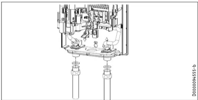
Technical line drawing of a mechanical assembly with no visible text or symbols▶ Connected braided steel flex connectors (recommended for hot outlet, required for cold inlet, not supplied) to the twin 12 " NPT male connectors.
▶ Open the shut-off valve in the cold water inlet line.
When all plumbing work is completed, check for leaks and take corrective action before proceeding.
10.3 Aerator installation at connected faucet
DHC 3/3.5-1 Trend ships with a 0.5 gpm (1.9 l/min) pressure compensating flow-reducer/aerator that must be installed on the faucet the water heater is connected to. Failure to install the aerator may result in lower water temperatures than desired.
DHC 4/6-2 Trend ships with a 1.0 gpm (3.8 l/min) aerator and 2 x 0.5 gpm (1.9 l/min) aerators, allowing for maximum installation flexibility. A single 0.5 gpm or 1.0 gpm aerator (depending on required temperature rise) should be installed when the unit is used at the [low] power output setting (jumper position 1). At the [high] power output setting (factory default, jumper position 2), the unit may be plumbed to a single sink using the 1.0 gpm aerator, or to two sinks using the 2 x 0.5 gpm aerators. Failure to install the aerator(s) may result in lower water temperatures than desired.
10.4 Electrical connection

WARNING: Electrocution
Before beginning any work on the electric installation, be sure that main breaker panel switches are "Off" to avoid any danger of electric shock. All mounting and plumbing must be completed before proceeding with electrical hook-up.
The unit must be properly grounded in accordance with state and local codes, or in absence of such codes, in accordance with national electric code or the Canadian electric code. Failure to electrically ground the product could result in serious personal injury or death.

WARNING Electrocution
The connection to the power supply is only permissible as a permanent connection in conjunction with a 34 " Romex clamp. Ensure the water heater can be separated from the power supply by an isolator that disconnects all poles with at least 1/8" (3 mm) contact separation.

CAUTION: DO NOT INSTALL IN A BATH ENCLOSURE FOR SHOWER STALL. DO NOT CONNECT TO A REGENERATED WATER SOFTENER OR A WATER PLY OF SALT WATER.
FOR USE ON AN INDIVIDUAL BRANCH CIRCUIT ONLY.
CAUTION: CONNECT ONLY TO A CIRCUIT PROTECTED BY A CLASS A GROUND FAULT INTERRUPTER
USE BONDING CONDUCTOR IN ACCORDANCE WITH THE CANADIAN ELECTRICAL CODE, PART I

Supply this appliance only from a grounded system. A green terminal (or a wire connector marked "G", "GR", "GROUND", OR "GROUNDING") is provided for wiring the appliance. To reduce the risk of electric shock, connect this terminal or connector to the grounding terminal of the electric service or supply panel with a continuous copper wire in accordance with the electrical installation code.

Material losses
Observe the type plate. The specified rated voltage must match the supply line voltage.

Material losses
The DHC 3/3.5-1 Trend must only be connected to a 120 V electrical supply. Connecting the DHC 3/3.5-1 Trend to a 208-240 V electrical supply will permanently damage the unit and void the factory warranty.
▶ All electrical work must comply with national and applicable state and local electrical codes.
The DHC Trend should be connected to a properly grounded dedicated branch circuit of proper voltage rating. In installations with several DHC Trend units, each unit requires an independent circuit. Please refer to the technical data table for the correct wire and circuit breaker size.
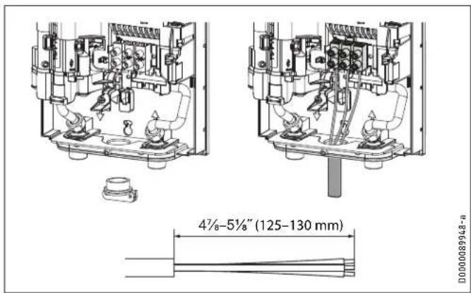
▶ A 34 " Romex clamp (required, not supplied) should be installed in the opening located between the hot and cold water connections. The wire should be fed through the Romex clamp. The "live" wires must be connected to the slots on the terminal block marked N and L (DHC 3/3.5-1 Trend only) or L and L (all other versions). The ground wire must be connected to the slot marked with the ground symbol. See section 16.2, "Wiring diagrams," pg. 16.
text_image
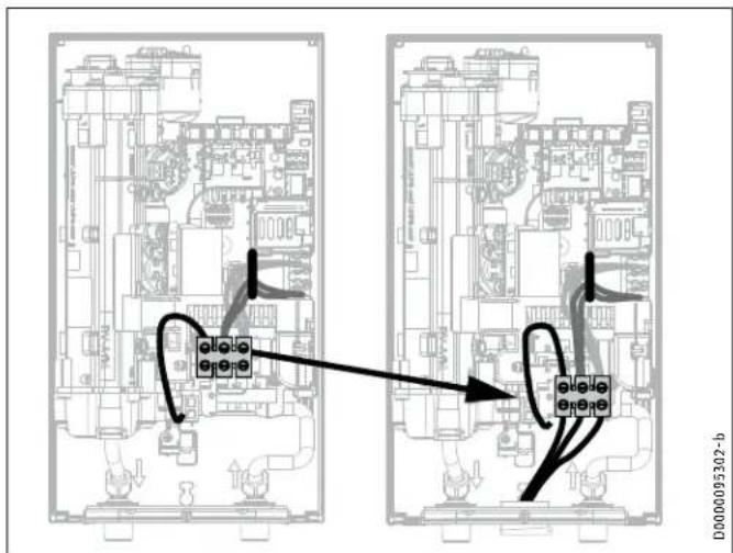
4½-5½" (125-130 mm) D000089948-a10.5 Electrical connection with short power cable
If the power cable is not quite long enough, the wiring block can be installed closer to the aperture in the water heater.
▶ Reposition the wiring block from the top to the bottom. To do so, unclip the wiring block by pushing it firmly to the left and pulling it forwards.
text_image
D0000095302-b▶ Clip the wiring block in at the bottom by pushing it inwards and to the left until it clicks into place.
10.6 Wiring block
Consult the chart below for the recommended torque amounts on the wiring block screws.
Screw Size (mm) Min. Torque (N·cm) Min. Torque (Lbf·in)
M6 200-250 17.7-22.1
Using the proper torque specifications to secure wire to the wiring block helps to avoid personal loss or property damage.
11. Commissioning
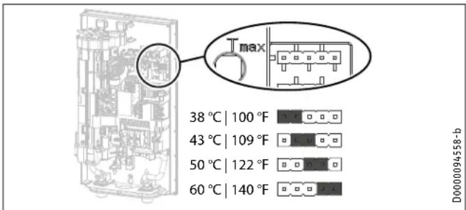
11.1 Temperature setting via jumper slot
The maximum outlet temperature of each jumper position during normal load operation depends on the operating voltage, flow rate, and incoming water temperature. See tables below for maximum temperature output at 240 V and 208 V nominal operating voltages.
text_image
38 °C | 100 °F 43 °C | 109 °F 50 °C | 122 °F 60 °C | 140 °FJumper position (240 V) Description
38 °C | 100 °F@ 240 V Code-compliant hand washing applications (factory default setting)
43°C | 109°F @ 240 V Applications where risk of scalding may be a concern
50 °C | 122 °F@ 240 V DHW for kitchen sink, utility sink, etc.
60 °C | 140 °F@ 240 V Commercial applications (kitchens, etc.), health code requirements
No jumper Limit 38°C | 100°F
Jumper position (208 V) * Description
32°C | 90°F @ 208 V Lukewarm water for hand washing (factory default setting)
36 °C | 97°F @ 208 V Code-compliant hand washing applications
41°C | 106 °F @ 208 V Warm water for hand washing
49°C | 120°F @ 208 V DHW for kitchen sink, utility sink, etc.
No jumper Limit 32 °C | 90°F
*All listed output temperatures assume an incoming water temperature of 15 °C | 59°F
▶ Install the jumper in the required position on the “ T_max ” pin strip.

CAUTION Burns
If the water supplied to the appliance is preheated, the internal anti-scalding protection limit may be exceeded. In such cases, limit the temperature with an upstream central thermostatic valve.
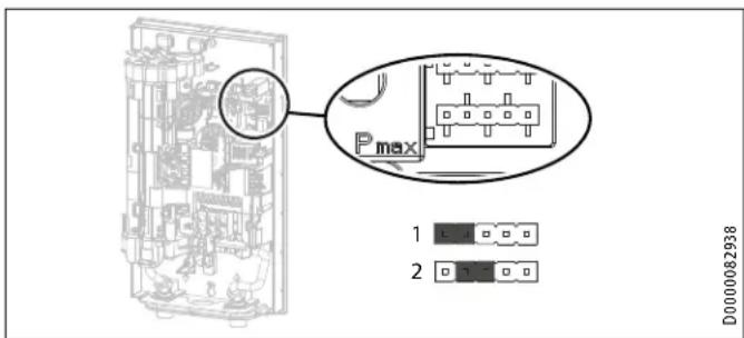
11.2 Changing power output via jumper slot
If you select a value other than the factory default setting, you will need to reposition the jumper.
text_image
Pmax 1 2 D0000082938▶ Install the jumper in the required position on the "P _max " pin strip.
| Jumper position | Power output | ||
| DHC 3/3.5-1 Trend | DHC 4/6-2 Trend | ||
| 1 [low] | @ 120 V | 3.0 kW | - |
| @ 208 V | - | 2.9 kW | |
| @ 240 V | - | 3.8 kW | |
| 2 [high] factory default | @ 120 V | 3.5 kW | - |
| @ 208 V | - | 4.5 kW | |
| @ 240 V | - | 6.0 kW | |
| No jumper [low] | @ 120 V | 3.0 kW | - |
| @ 208 V | - | 2.9 kW | |
| @ 240 V | - | 3.8 kW | |
| Jumper position | Power output | ||
| DHC 8/10-2 Trend | DHC 12/15-2 Trend | ||
| 1 [low] | @ 208 V | 5.4 kW | 9.0 kW |
| @ 240 V | 7.2 kW | 12.0 kW | |
| 2 [high] | @ 208 V | 7.2 kW | 10.8 kW |
| factory default | @ 240 V | 9.6 kW | 14.4 kW |
| No jumper | @ 208 V | 5.4 kW | 9.0 kW |
| [low] | @ 240 V | 7.2 kW | 12.0 kW |
▶ Mark the selected power output on the type plate. Use a ball-point pen to do this.
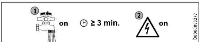
11.3 Initial start-up

Note
During initial start-up, you MUST engage the AE3 safety switch by depressing the white reset button before supplying power to the water heater. The unit will NOT operate until the safety switch has been engaged.
text_image
① on ≥ 3 min. ② on D0000053277▶ Open and close all connected draw-off valves at least five times total. Let water run for at least three minutes, until all air has been purged from the pipework and the water heater.
INSTALLATION
Water heater shutdown
▶ Ensure there are no water leaks from any plumbing connections.
11.3.1 Initial AE3 safety switch activation
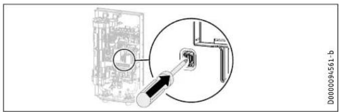
text_image
D0000094561-b▶ Engage the AE3 safety switch by firmly pressing the white reset button until it clicks and fully locks in place (the water heater is delivered with the safety switch disengaged).
natural_image
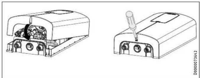
Technical line drawings of two electronic device components with internal wiring and a screwdriver (no text or symbols)▶ Hook the water heater cover into the water heater back panel at the top rear. Pivot the cover downwards. Check that the cover is securely seated at both top and bottom.
▶ Secure the cover with the screw.
▶ Remove the protective film from the front panel.
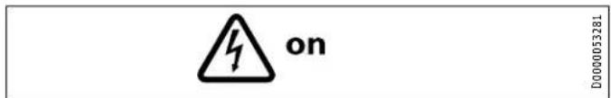
text_image
on D0000053281▶ Switch on the power supply.
11.3.2 Water heater handover
Explain the water heater functions to users, and familiarize them with how it works.
▶ Make the user aware of potential dangers, especially the risk of scalding.
▶ Hand over the instructions.
11.4 Operation with preheated water
The maximum inlet temperature may be limited by installing a central thermostatic valve. Use the thermostatic valve for central premixing, for example when operating a tankless water heater with preheated water.
11.5 Recommissioning
Material losses
To ensure that the direct coil heating system is not damaged following an interruption to the water supply, the water heater must be restarted by taking the following steps:
▶ Disconnect the water heater from the power supply by turning the connected circuit breaker.
▶ Open and close all connected draw-off valves at least 5 times, for at least 3 minutes total, until all air has been purged from the pipework and the water heater.
▶ Switch the power back ON.
12. Water heater shutdown
▶ Shut off power to the unit at the breaker panel by making sure that connected circuit breakers are "OFF" to avoid any danger of electric shock.
Drain the water heater (See section 14.1, "Draining the water heater," pg. 14").
13. Service information
Connection overview/component overview
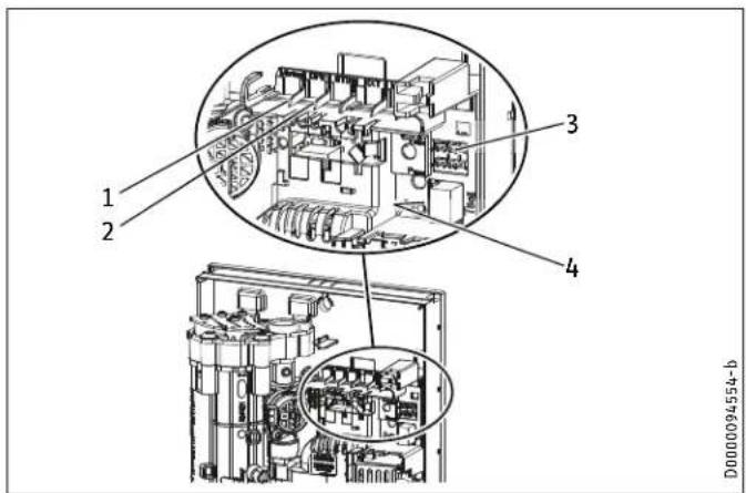
text_image
1 2 3 4 D000094554-b1 Flow sensor
2 High limit safety cut-out, automatic reset, Klixon
3 Pin strips for power output and temperature selection
4 Diagnostic lights
14. Maintenance

WARNING Electrocution
Before beginning any work on the water heater, be sure that main breaker panel switches are "Off" to avoid any danger of electric shock.
14.1 Draining the water heater
The water heater can be drained for maintenance work.

WARNING Burns
Hot water may escape when you drain the water heater.
▶ Close the shut-off valve in the cold water inlet line.
▶ Open all draw-off valves.
▶ Undo the water connections on the water heater.
- Store the dismantled water heater free from the risk of frost, as water residues remaining inside the water heater can freeze and cause damage.
14.2 Cleaning the filter screen

WARNING Burns
Hot water may escape when you drain the water heater.

Material losses
To ensure that the Direct Coil ^™ heating system is not damaged following an interruption to the water supply, the water heater must be restarted by taking the following steps.
▶ Shut off power to the unit at the breaker panel by making sure that connected circuit breakers are "OFF" to avoid any danger of electric shock.
▶ Open and close all connected draw-off valves at least 5 times, for at least 3 minutes total, until all air has been purged from the pipework and the water heater.
▶ Switch the power back ON at the breaker panel.
The DHC Trend has a built in sediment filter screen that should be cleaned periodically:
▶ Turn off power to the water heater at the circuit breaker.
▶ Turn off the water supply to the water heater at the shut-off valve.
▶ Open a connected hot water tap to relieve built-up pressure (this will minimize leakage when removing the connection from the cold water inlet).
▶ Disconnect the braided steel flex connector from the cold water inlet fitting (right).
▶ To remove the filter screen from the bottom of the cold water inlet, carefully insert a flathead screwdriver just above the plastic lip of the filter screen, and gently pull downward.
▶ Clean the filter screen, re-insert securely into the cold water inlet fitting, and reconnect the braid steel flex connector to the cold water inlet.
▶ Open the cold water supply shut-off valve.
▶ Vent the air from pipes and the water heater by opening and closing all connected draw-off valves at least 5 times, for at least 3 minutes total, until all air has been purged from the pipework and the water heater.
▶ Turn on circuit breaker to bring electrical power to the unit.
15. Troubleshooting

WARNING Electrocution
Never remove or reinstall the water heater's cover unless the electricity servicing the unit is turned off. Failure to do so could result in personal injury or death.

WARNING Electrocution
To test the water heater using the internal diagnostic lights, it must be connected to the power supply.
When testing with the cover off, never touch any part of the water heater. Doing so could result in serious personal injury or death.

Note
When testing the water heater using the diagnostic lights, water must be flowing through the unit.
Diagnostic lights
| ●○○ | Red Lights up in the event of a fault |
| ○●○ | Yellow Lights up in heating mode/flashes when output limit reached |
| ○○● | Green Flashing: Water heater connected to power supply |
| Diagnostic Lights Problem Cause Solution | |||
| No LED is lit The water heater does not heat up | There is no power | Check to ensure the connected circuit breaker in the main breaker panel hasn't tripped. Reset if necessary | |
| The PCB is faulty | Replace the function module | ||
| Green flashing, yellow off, red off | No DHW | The shower head/aerator is scaled up | Descale or replace the shower head/aerator if necessary |
| The filter screen in the cold water inlet is dirty | Clean the filter screen. See section 14.2, “Cleaning the filter screen,” pg. 14 | ||
| The flow sensor is not plugged in | Connect the cable to the PCB | ||
| The flow sensor is faulty | Replace the function module | ||
| The PCB is faulty | Replace the function module | ||
| Green flashing, yellow on, red off | The outlet temperature does not match the set value | The device is connected to a power supply <240 V | Please observe the information in section 11.1, “Temperature setting via jumper slot”, pg. 12 |
| The tap is faulty | Replace the tap | ||
| The heating system is faulty | Replace the function module | ||
| The PCB is faulty | Replace the function module | ||
| Green flashing, yellow off, red on | No DHW | Air detected | Continue draw-off for >1 minute |
| AE3 safety switch not activated during commissioning | Activate AE3 safety switch by pressing the reset button firmly. See section 11.3.1, “Initial AE3 safety switch activation,” pg. 13 | ||
| AE3 safety switch triggered by self-resetting high limit safety cut-out | Check high limit safety cut-out Klixon (plug-in connection, connecting cable); activate AE3 safety switch | ||
| AE3 safety switch responds again after high limit safety cut-out Klixon has been checked; high limit safety cut-out faulty | Replace high limit safety cut-out Klixon activate AE3 safety switch and draw off water at the maximum set value for >1 min | ||
| Safety switch responds again; PCB faulty | Replace the function module | ||
| PCB faulty (lead break or short circuit in inlet sensor) | Replace the function module | ||
16. Specification
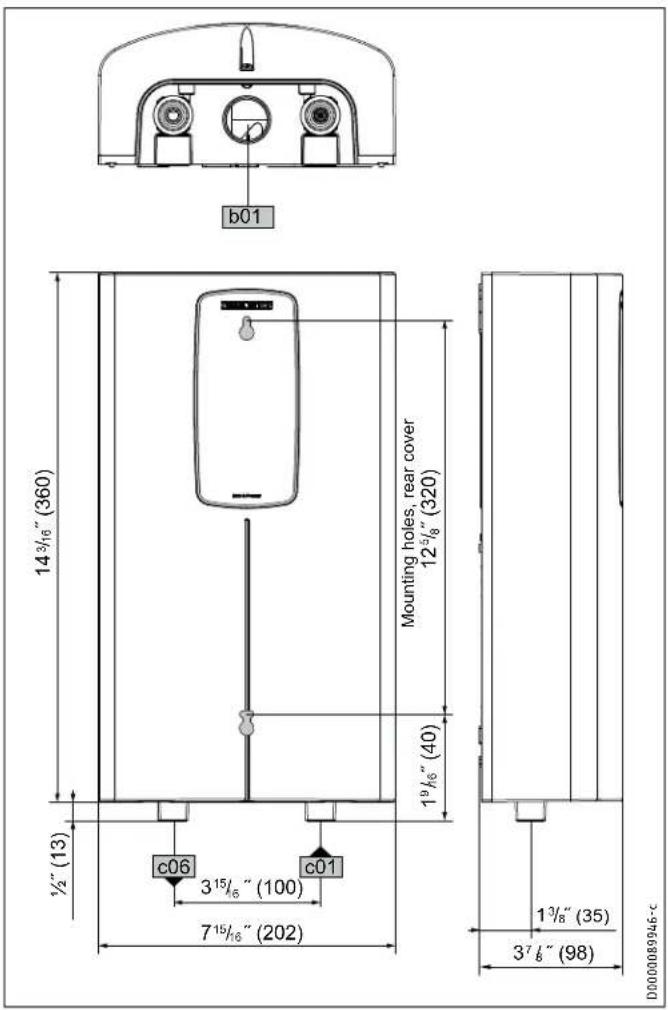
16.1 Dimensions
text_image
b01 14 3/16" (360) Mounting holes, rear cover 12 5/8" (320) 19 1/8" (40) 1/2" (13) c06 3 15/8" (100) 7 15/8" (202) c01 1 3/8" (35) 3 7/8" (98) D0000089946-c| DHC Trend | |
| b02 Entry electrical cables | |
| c01 Cold water inlet Male thread 1/2" NPT | |
| c06 DHW outlet Male thread 1/2" NPT |
16.2 Wiring diagrams
DHC 3/3.5-1 Trend

1/N/GND \~ 120V
DHC 4/6-2 Trend

2/GND \~ 208 / 240V
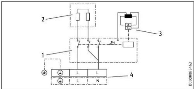
text_image
2 1 L L N 4 3 D00000854631 Power PCB with integral safety switch
2 Direct Coil ™ heating system
3 Self-resetting high limit safety cut-out, Klixon
4 Wiring block
1 Power PCB with integral safety switch
2 Direct Coil ^TM heating system
3 Self-resetting high limit safety cut-out, Klixon
4 Wiring block
16.3 Hot water output
The domestic hot water (DHW) output is subject to the connected power supply, the water heater's connected load, and the cold water inlet temperature. The rated voltage and rated output can be found on the type plate.
Power output in kW 100 °F DHW output in gpm
| Rated voltage Cold water inlet temperature | |||||||
| Model | 120 V | 208 V | 240 V | 41°F | 50°F | 59°F | 68°F |
| DHC3/3.5-1 | 3.0 | 0.35 | 0.41 | 0.5 | 0.64 | ||
| Trend | 3.5 | 0.41 | 0.48 | 0.58 | 0.75 | ||
| 2.9 | 0.34 | 0.4 | 0.48 | 0.62 | |||
| DHC4/6-2 | 4.5 | 0.52 | 0.61 | 0.75 | 0.96 | ||
| Trend | 3.8 | 0.44 | 0.52 | 0.63 | 0.81 | ||
| 6.0 | 0.69 | 0.82 | 1.0 | 1.28 | |||
| 5.4 | 0.63 | 0.74 | 0.9 | 1.15 | |||
| DHC8/10-2 | 7.2 | 0.83 | 0.98 | 1.2 | 1.54 | ||
| Trend | 7.2 | 0.83 | 0.98 | 1.2 | 1.54 | ||
| 9.6 | 1.11 | 1.31 | 1.6 | 2.05 | |||
| 9.0 | 1.04 | 1.23 | 1.5 | 1.92 | |||
| DHC12/15-2 | 10.8 | 1.24 | 1.46 | 1.78 | 2.28 | ||
| Trend | 12.0 | 1.39 | 1.64 | 2.0 | 2.56 | ||
| 14.4 | 1.67 | 1.97 | 2.4 | 3.07 | |||
Power output in kW 122 °F DHW output in gpm
| Rated voltage Cold water inlet temperature | |||||||
| Model | 120 V | 208 V | 240 V | 41°F | 50°F | 59°F | 68°F |
| DHC3/3.5-1 | 3.0 | - | 0.28 | 0.33 | 0.38 | ||
| Trend | 3.5 | 0.3 | 0.33 | 0.38 | 0.44 | ||
| DHC4/6-2 | 2.9 | - | 0.28 | 0.31 | 0.37 | ||
| 4.5 | 0.38 | 0.43 | 0.49 | 0.57 | |||
| Trend | 3.8 | 0.32 | 0.36 | 0.41 | 0.48 | ||
| 6.0 | 0.51 | 0.57 | 0.65 | 0.76 | |||
| DHC8/10-2 | 5.4 | 0.46 | 0.51 | 0.59 | 0.68 | ||
| 7.2 | 0.61 | 0.68 | 0.78 | 0.91 | |||
| Trend | 7.2 | 0.61 | 0.68 | 0.78 | 0.91 | ||
| 9.6 | 0.81 | 0.91 | 1.04 | 1.21 | |||
| DHC12/15-2 | 9.0 | 0.76 | 0.85 | 0.98 | 1.14 | ||
| 10.8 | 0.9 | 1.02 | 1.16 | 1.35 | |||
| Trend | 12.0 | 1.01 | 1.14 | 1.3 | 1.52 | ||
| 14.4 | 1.21 | 1.37 | 1.56 | 1.82 | |||
Power output in kW 38 °C DHW output in L/min
| Model | Rated voltage | Cold water inlet temperature | |||||
| 120 V | 208 V | 240 V | 5°C | 10°C | 15°C | 20°C | |
| DHC3/3.5-1 | 3.0 | 1.3 | 1.5 | 1.9 | 2.4 | ||
| Trend | 3.5 | 1.5 | 1.8 | 2.2 | 2.8 | ||
| DHC4/6-2 | 2.9 | 1.3 | 1.5 | 1.8 | 2.3 | ||
| 4.5 | 1.9 | 2.3 | 2.8 | 3.6 | |||
| Trend | 3.8 | 1.7 | 2.0 | 2.4 | 3.0 | ||
| 6.0 | 2.6 | 3.1 | 3.7 | 4.8 | |||
| DHC8/10-2 | 5.4 | 2.3 | 2.8 | 3.4 | 4.3 | ||
| 7.2 | 3.1 | 3.7 | 4.5 | 5.7 | |||
| Trend | 7.2 | 3.1 | 3.7 | 4.5 | 5.7 | ||
| 9.6 | 4.2 | 4.9 | 6.0 | 7.6 | |||
| DHC12/15-2 | 9.0 | 3.9 | 4.6 | 5.6 | 7.1 | ||
| 10.8 | 4.6 | 5.5 | 6.6 | 8.5 | |||
| Trend | 12.0 | 5.2 | 6.1 | 7.5 | 9.5 | ||
| 14.4 | 6.2 | 7.3 | 8.9 | 11.4 | |||
Power output in kW 50 °C DHW output in L/min
| Model | Rated voltage | Cold water inlet temperature | |||||
| 120 V | 208 V | 240 V | 5°C | 10°C | 15°C | 20°C | |
| DHC3/3.5-1 | 3.0 | 1.0 | 1.1 | 1.2 | 1.4 | ||
| Trend | 3.5 | 1.1 | 1.3 | 1.4 | 1.7 | ||
| DHC4/6-2 | 2.9 | - | 1.1 | 1.2 | 1.4 | ||
| 4.5 | 1.4 | 1.6 | 1.8 | 2.1 | |||
| Trend | 3.8 | 1.2 | 1.4 | 1.6 | 1.8 | ||
| 6.0 | 1.9 | 2.1 | 2.4 | 2.9 | |||
| DHC8/10-2 | 5.4 | 1.7 | 1.9 | 2.2 | 2.6 | ||
| 7.2 | 2.3 | 2.6 | 2.9 | 3.4 | |||
| Trend | 7.2 | 2.3 | 2.6 | 2.9 | 3.4 | ||
| 9.6 | 3.0 | 3.4 | 3.9 | 4.6 | |||
| DHC12/15-2 | 9.0 | 2.9 | 3.2 | 3.7 | 4.3 | ||
| 10.8 | 3.4 | 3.8 | 4.4 | 5.1 | |||
| Trend | 12.0 | 3.8 | 4.3 | 4.9 | 5.7 | ||
| 14.4 | 4.6 | 5.1 | 5.9 | 6.9 | |||
16.4 Application areas/conversion table
Here, data is shown for electrical resistivity and electrical conductivity.
| Standard specification at 15 °C | 20 °C | 25 °C | ||||||
| Min. resistivity ≥ | Max. conductivity ≤ | Min. resistivity ≥ | Max. conductivity ≤ | Min. resistivity ≥ | Max. conductivity ≤ | |||
| cm | mS/m | S/cm | cm | mS/m | S/cm | cm | mS/m | S/cm |
| 1100 | 91 | 910 | 970 | 103 | 1031 | 895 | 112 | 1117 |
16.4.1 Sizing the pipework
When calculating the size of the pipework, an water heater pressure drop of 14.5 psi (0.97 bar) is recommended.
16.5 Fault conditions
In the event of a fault, temperatures up to 176^ F ( 80^ C) at a pressure of 145 psi (1.0 MPa) can occur briefly in the installation.
16.6 Data tables
| DHC 3/3.5-1 Trend DHC 4/6-2 Trend | |||
| Item no. 200060 200062 | |||
| Electrical data | |||
| Phase (50/60 Hz) | 1/N/GND | 1/N/GND | 2/GND | |
| Rated voltage | 120 V | 240 V | 208 V |
| Rated output ^1 , jumper position 1 [low] / 2 [high] | 3.0 kW / 3.5 kW | 3.8 kW / 6.0 kW | 2.9 kW / 4.5 kW |
| Amperage draw, jumper position 1 [low] / 2 [high] | 25 A / 29.2 A | 15.8 A / 25 A | 13.9 A / 21.7 A |
| Min. recommended circuit breaker size ^2 , jumper position 1 [low] / 2 [high] | 25 A / 30 A | 20 A / 25 A | 15 A / 25 A |
| Min recommended wire size ^3 (copper), jumper position 1 [low] / 2 [high] | 10/2 AWG / 10/2 AWG | 12/2 AWG / 10/2 AWG | 14/2 AWG / 10/2 AWG |
| Min. resistivity 15 ≥ | 1100 Ω cm | ||
| Max. conductivity 15 ≤ | 910 μS/cm | ||
| Connections | |||
| Water connections | ^1/_2" NPT | ||
| Application limits | |||
| Maximum permissible pressure | 145 psi (1 MPa) | ||
| Maximum inlet temperature for reheating | 131°F (55°C) | ||
| Maximum inlet temperature | 149°F (65°C) | ||
| Temperature setting values @ 240 V | 100/109/122/140°F (38/43/50/60°C) | ||
| Hydraulic data | |||
| Minimum water flow to activate unit | 0.264 gal (1.0 l/min) | ||
| Nominal water volume | 0.07 gal (0.277 l) | ||
| Other | |||
| Type of installation | Over-sink/under-sink | ||
| Protection class | 1 | ||
| Insulating block | Glass-reinforced polyamide | ||
| Heating system | Direct Coil ^TM | ||
| Cover and back panel | Plastic | ||
| Color | White | ||
| Dimensions | |||
| Height | 14 ^1/_6" (360 mm) | ||
| Width | 8" (202 mm) | ||
| Depth | 3 ^7/_8" (98 mm) | ||
| Weights | |||
| Weight | 5.5 lbs (2.5 kg) | ||
DHC 3/3.5-1 Trend ships with a 0.5 gpm (1.9 l/min) pressure compensating flow-reducer/aerator that must be installed.
DHC 4/6-2 Trend ships with 2 x 0.5 gpm (1.9 l/min) and a 1.0 gpm (3.8 l/min) pressure compensating flow-reducer/aerator that must be installed. See section 10.3, "Aerator installation at connected faucet," pg. 10 for more information.
^1 Factory default setting is jumper position 2 [high]
^2 Overcurrent protection sized at 100% of load. Tankless water heaters are considered a non-continuous load. Use only GFCI Class A circuit breakers.
^3 Copper conductors with a temperature rating of 75^ C or greater must be used. Conductors should be sized to maintain a voltage drop of less than 3% under load. These are our recommendations. Check local codes for compliance if necessary.
INSTALLATION
Specification
| DHC 8/10-2 Trend DHC 12/15-2 Trend | ||||
| Item no. 200063 200064 | ||||
| Electrical data | ||||
| Phase (50/60 Hz) 1/N/GND | 2/GND | ||||
| Rated voltage | 240 V | 208 V | 240 V | 208 V |
| Rated output ^1 , jumper position 1 [low] / 2 [high] | 7.2 kW / 9.6 kW | 5.4 kW / 7.2 kW | 12.0 kW / 14.4 kW | 9.0 kW / 10.8 kW |
| Amperage draw, jumper position 1 [low] / 2 [high] | 30 A / 40 A | 26 A / 34.6 A | 50 A / 60 A | 43.3 A / 52 A |
| Min. recommended circuit breaker size ^2 , jumper position 1 [low] / 2 [high] | 30 A / 40 A | 30 A / 35 A | 50 A / 60 A | 50 A / 60 A |
| Min recommended wire size ^3 (copper), jumper position 1 [low] / 2 [high] | 10/2 AWG / 8/2 AWG | 10/2 AWG / 8/2 AWG | 8/2 AWG / 6/2 AWG | 8/2 AWG / 6/2 AWG |
| Min. resistivity p15 ≥ | 1100 Ω cm | |||
| Max. conductivity σ15 ≤ | 910 μS/cm | |||
| Connections | ||||
| Water connections | 1/2" NPT | |||
| Application limits | ||||
| Maximum permissible pressure | 145 psi (1 MPa) | |||
| Maximum inlet temperature for reheating | 131°F (55°C) | |||
| Maximum inlet temperature | 149°F (65°C) | |||
| Temperature setting values @ 240 V | 100/109/122/140°F (38/43/50/60°C) | |||
| Hydraulic data | ||||
| Minimum water flow to activate unit | 0.264 gal (1.0 l/min) | |||
| Nominal water volume | 0.07 gal (0.277 l) | |||
| Other | ||||
| Type of installation | Over-sink/under-sink | |||
| Protection class | 1 | |||
| Insulating block | Glass-reinforced polyamide | |||
| Heating system | Direct Coil | |||
| Cover and back panel | Plastic | |||
| Color | White | |||
| Dimensions | ||||
| Height | 14^12/8'' (360 mm) | |||
| Width | 8" (202 mm) | |||
| Depth | 3718'' (98 mm) | |||
| Weights | ||||
| Weight | 5.5 lbs (2.5 kg) | |||
^1 Factory default setting is jumper position 2 [high]
^2 Overcurrent protection sized at 100% of load. Tankless water heaters are considered a non-continuous load. Use only GFCI Class A circuit breakers.
^3 Copper conductors with a temperature rating of 75^ C or greater must be used. Conductors should be sized to maintain a voltage drop of less than 3% under load.
These are our recommendations. Check local codes for compliance if necessary.
- Spare parts
| No. | Spare part DHC 3/3.5-1 Trend | DHC 4/6-2 Trend DHC 8/10-2 Trend DHC 12/15-2 Trend | |||
| 1 | Housing (front) | 348147 | 348147 | 348147 | 348147 |
| 8 | Housing (back) | 348143 | 348143 | 348143 | 348143 |
| 10 | Function module | 348150 | 348151 | 348152 | 348153 |
| 12 | Self-resetting high limit safety cut-out, Klixon | 340529 | 340529 | 340529 | 340529 |
| 14 | Pipe elbow set | 340542 | 340542 | 340542 | 340542 |
| 15 | Pipe elbow connection set (includes clips and gaskets) | 320540 | 320540 | 320540 | 320540 |
| 21 | Jumper plug (red) | 283455 | 283455 | 283455 | 283455 |
| 22 | Wiring block | 326655 | 326655 | 326655 | 326655 |
| 23 | Electronics cover | 344146 | 344146 | 344146 | 344146 |
| 40 | Water connection fittings (2) - 12" NPT / G^38 " | 326589 | 326589 | 326589 | 326589 |
| 41 | Locking sheet | 326234 | 326234 | 326234 | 326234 |
| 42 | Filter screen | 275981 | 275981 | 275981 | 275981 |
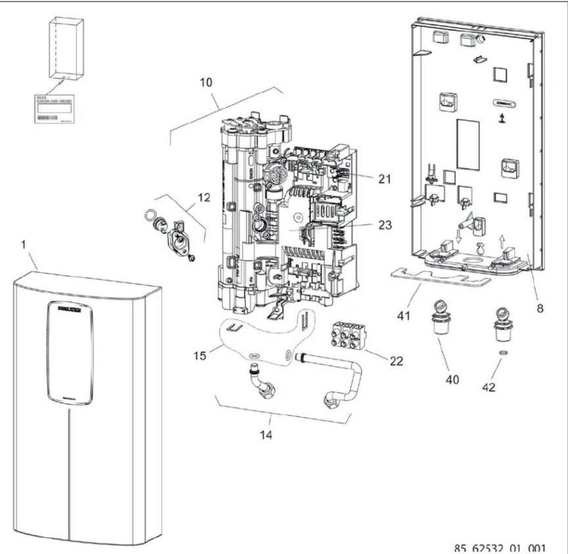
text_image
Exploded view diagram of an air conditioner unit with numbered components and control panel labels18. Warranty
Subject to the terms and conditions set forth in this limited warranty, Stiebel Eltron, Inc. (the "Manufacturer") hereby warrants to the original purchaser (the "Owner") that each Tankless Electric Domestic Hot Water Heater (the "Heater") shall not (i) leak due to defects in the Manufacturer's materials or workmanship for a period of ten (10) years from the date of purchase or (ii) fail due to defects in the Manufacturer's materials or workmanship for a period of three (3) years from the date of purchase. As Owner's sole and exclusive remedy for breach of the above warranty, Manufacturer shall, at the Manufacturer's discretion, send replacement parts for local repair; retrieve the unit for factory repair, or replace the defective Heater with a replacement unit with comparable operating features. Manufacturer's maximum liability under all circumstances shall be limited to the Owner's purchase price for the Heater.
This limited warranty shall be the exclusive warranty made by the Manufacturer and is made in lieu of all other warranties, express or implied, whether written or oral, including, but not limited to warranties of merchantability and fitness for a particular purpose. Manufacturer shall not be liable for incidental, consequential or contingent damages or expenses arising directly or indirectly from any defect in the Heater or the use of the Heater. Manufacturer shall not be liable for any water damage or other damage to property of Owner arising, directly or indirectly, from any defect in the Heater or the use of the Heater. Manufacturer alone is authorized to make all warranties on Manufacturer's behalf and no statement, warranty or guarantee made by any other party shall be binding on Manufacturer.
Manufacturer shall not be liable for any damage whatsoever relating to or caused by:
- any misuse or neglect of the Heater, any accident to the Heater, any alteration of the Heater, or any other unintended use;
- acts of God and circumstances over which Manufacturer has no control;

The installation, electrical connection and first operation of this appliance should be carried out by a qualified installer.

The company does not accept liability for failure of any goods supplied which have not been installed and operated in accordance with the manufacturer's instructions.
Environment and recycling
Please help us to protect the environment by disposing of the packaging in accordance with the national regulations for waste processing.
- installation of the Heater other than as directed by Manufacturer and other than in accordance with applicable building codes;
- failure to maintain the Heater or to operate the Heater in accordance with the Manufacturer's specifications;
- operation of the Heater under fluctuating water pressure or in the event the Heater is supplied with non-potable water, for any duration;
- improper installation and/or improper materials used by any installer and not relating to defects in parts or workmanship of Manufacturer;
- moving the Heater from its original place of installation;
- exposure to freezing conditions;
- water quality issues such as corrosive water, hard water, and water contaminated with pollutants or additives;
Should owner wish to return the Heater to manufacturer for repair or replacement under this warranty, Owner must first secure written authorization from Manufacturer. Owner shall demonstrate proof of purchase, including a purchase date, and shall be responsible for all removal and transportation costs. If Owner cannot demonstrate a purchase date this warranty shall be limited to the period beginning from the date of manufacture stamped on the Heater. Manufacturer reserves the right to deny warranty coverage upon Manufacturer's examination of Heater. This warranty is restricted to the Owner and cannot be assigned.
Some States and Provinces do not allow the exclusion or limitation of certain warranties. In such cases, the limitations set forth herein may not apply to the Owner. In such cases this warranty shall be limited to the shortest period and lowest damage amounts allowed by law. This warranty gives you specific legal rights and you may also have other rights which vary from State to State or Province to Province.
Owner shall be responsible for all labor and other charges incurred in the removal or repair of the Heater in the fi eld. Please also note that the Heater must be installed in such a manner that if any leak does occur, the flow of water from any leak will not damage the area in which it is installed.
This Warranty is valid for U.S.A. & Canada only. Warranties may vary by country. Please consult your local Stiebel Eltron Representative for the Warranty for your country.
TABLA DE CONTENIDO
natural_image
Diagram showing a magnified view of an electronic device with a screwdriver inserted into a socket (no text or symbols present)D0000094561-b
natural_image
Technical line drawings of two electronic device components with no visible text or symbolsnatural_image
Technical line drawing of an electrical control panel with no visible text or symbolsnatural_image
Diagram showing a magnified view of a mechanical component inserted into a bracket, with no visible text or symbols.D0000094561-b
natural_image
Technical line drawings of two electronic device components with internal wiring (no text or symbols)natural_image
Line drawing of a rectangular device with a vertical screen and labeled component (no text or symbols)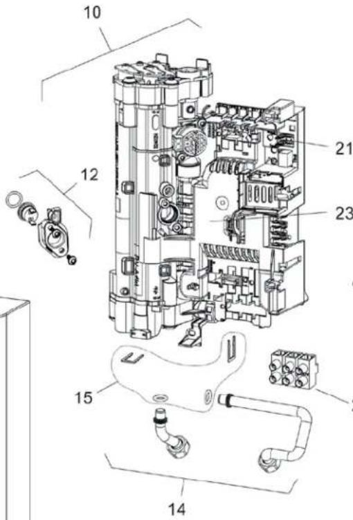
text_image
Technical diagram of an electrical switchgear assembly with numbered components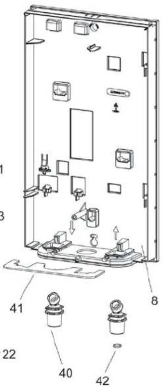
text_image
Technical diagram of a refrigerator internal components with numbered parts and labeled parts85 62532 01 001
19. Garantía
10.1 Installation murale standard 50
natural_image
Diagram showing a magnified view of an electronic component with a screwdriver inserted into a socket (no text or symbols present)D0000094561-b
10.1 Installation murale standard
natural_image
Line drawing of a mechanical component with a screwdriver inserted, no text or symbols present
natural_image
Technical line drawing of a mechanical device with internal components (no text or symbols)D0000094555-b
natural_image
Technical line drawing of an electrical component with no visible text or symbolstext_image
Diagram showing two electrical or circuit layout layouts with labeled components and directional arrows indicating connections.natural_image
Technical line drawings of two electronic device components with internal wiring and a screwdriver (no text or symbols)natural_image
Line drawing of a rectangular electronic device with a vertical screen and a base, labeled with number 1 (no text or symbols on the device itself)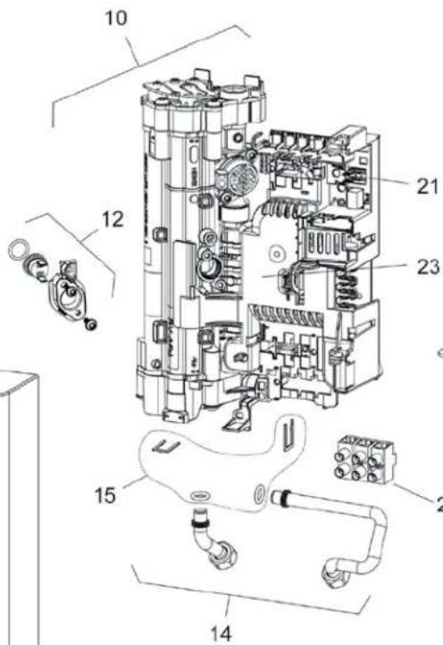
text_image
Technical diagram of an electrical switchgear assembly with numbered components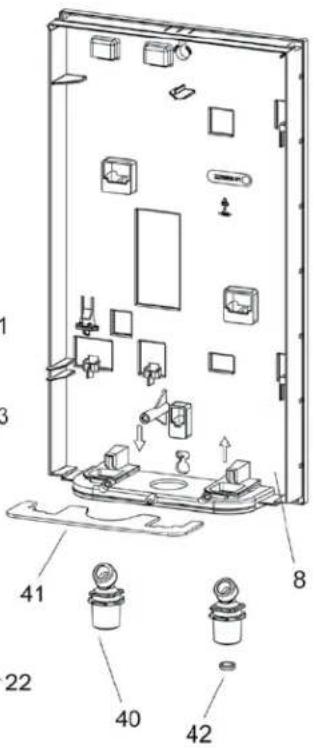
text_image
Technical diagram of a door panel with labeled components and numbered parts85 62532 01 001
18. Garantie
United States of America
STIEBEL ELTRON, Inc.
17 West Street | West Hatfield, MA 01088
Tel. 413.247.3380 | Fax 413.247.3369
Toll-free 800.582.8423
info@stiebel-eltron-usa.com
www.stiebel-eltron-usa.com
Austria
STIEBEL ELTRON Ges.m.b.H.
Eferdinger Str. 73 | 4600 Wels
Tel. 07242 47367-0 | Fax 07242 47367-42
info@stiebel-eltron.at
www.stiebel-eltron.at
Belgium
STIĚBEL ELTRON bvba/sprl
't Hofveld 6 - D1 | 1702 Groot-Bijgaarden
Tel. 02 42322-22 | Fax 02 42322-12
info@stiebel-eltron.be
www.stiebel-eltron.be
Czech Republic
STIEBEL ELTRON spol. s r.o.
Urzhumskaya street 4,
building 2 | 129343 Moscow
Tel. 0495 7753889 | Fax 0495 7753887
info@stiebel-eltron.ru
www.stiebel-eltron.ru
Slovakia
STIEBEL ELTRON Slovakia, s.r.o.
Hlavná 1 | 058 01 Poprad
Tel. 052 7127-125 | Fax 052 7127-148
info@stiebel-eltron.sk
www.stiebel-eltron.sk
Sweden
STENERGY
Vasagatan 14 | 545 30 Töreboda
Sales:
Tel. 0506 105-10 | info@stiebel-eltron.se
Technique & Service:
Tel. 0150 54200 | info@heatech.se
www.stiebel-eltron.se
Switzerland
STIEBEL ELTRON AG
United Kingdom and Ireland
STIEBEL ELTRON UK Ltd.
Unit 12 Stadium Court
Stadium Road | CH62 3RP Bromborough
Tel. 0151 346-2300 | Fax 0151 334-2913
info@stiebel-eltron.co.uk
www.stiebel-eltron.co.uk
STIEBEL ELTRON
Irrtum und technische Änderungen vorbehalten! | Subject to errors and technical changes! | Sous réserve d'erreurs et de modifications techniques! | Onder voorbehoud van vergissingen en technische wijzigingen! | Salvo error o modificación técnica! | Rätt till misstag och tekniska ändringar förbehalls! | Excepto erro du alteração técnica | Zastrzeżone zmiany techniczne i ewentualne błędy | Omyly a technické zmény jsou vyhrażeny! | A muszaki változtatások és tévedések jogát fenntartjuk! | Otcутствие ошибok ne garantiруется. Возможны технические изменения. | Chyby a technické zmény sú vyhradené! Stand 8643