
DEM - Boiler STIEBEL ELTRON - Free user manual and instructions
Find the device manual for free DEM STIEBEL ELTRON in PDF.

| Product type | Instantaneous water heater |
| Brand | Stiebel Eltron |
| Model | DEM (variants 3/4/6/7) |
| Use | Domestic hot water heating and preheated water backup |
| Dimensions (H x W x D) | 143 x 190 x 82 mm |
| Weight | 1.5 kg |
| Power supply | 200-240 V single-phase (DEM 3/4/6) or 380-400 V three-phase (DEM 7) |
| Nominal power | 3.5 to 6.5 kW depending on variant |
| Protection | IP 25 |
| Protection class | 1 |
| Max. admissible pressure | 1 MPa |
| Max. water inlet temperature (backup) | 50 °C |
| Outlet temperature | Adjustable from 30 to 50 °C (factory set 38 °C) |
| Max. flow rate | 2.0 to 3.7 l/min depending on variant |
| Heating system | Bare wire (limescale resistant) |
| Hydraulic connection | G 3/8 A |
| Cable length | 700 mm |
| Functions | Electronic regulation, automatic start when tap is opened |
| Cleaning and maintenance | Damp cloth, regular descaling of special aerator |
| Safety | Safety pressure switch, all-pole disconnection (3 mm), mandatory earthing |
| Supplied accessories | Filter, special aerator, 3/8 flexible hose (500 mm), T-piece, logo |
| Warranty | According to local subsidiary conditions |
Frequently Asked Questions - DEM STIEBEL ELTRON
User questions about DEM STIEBEL ELTRON
0 question about this device. Answer the ones you know or ask your own.
Ask a new question about this device
Download the instructions for your Boiler in PDF format for free! Find your manual DEM - STIEBEL ELTRON and take your electronic device back in hand. On this page are published all the documents necessary for the use of your device. DEM by STIEBEL ELTRON.
USER MANUAL DEM STIEBEL ELTRON
www.stiebel-eltron.com/registration

BESONDEREHINWEISE

www.stiebel-eltron.com/registration
INSTALLATION
Sicherheit
INSTALLATION
8. Sicherheit
X Volumenstrom in l/min
Y Temperaturerhöhung in K
1 3.5kW - 230V
2 4.4 kW - 230 V
3 5,7 kW - 230 V
4 6,5kW - 400V
- General information 33
- Safety 34
- Appliance description 35
- Settings 36
- Cleaning, care and maintenance 36
- Troubleshooting 36
INSTALLATION
- Safety 37
- Appliance description 37
9.Preparation 38 - Installation 38
- Commissioning 42
- Shutting down the system 45
- Troubleshooting 45
- Maintenance 47
- Specification 48
GUARANTEE
ENVIRONMENT AND RECYCLING
SPECIAL INFORMATION
- The appliance may be used by children over 3 years of age and persons with reduced physical, sensory or mental capabilities or a lack of experience and expertise, provided that they are supervised or they have been instructed on how to use the appliance safely and have understood the potential risks. Children must never play with the appliance. Cleaning and user maintenance must not be carried out by children without supervision.
- During operation, the tap can reach temperatures up to 55^ . There is a risk of scalding at outlet temperatures in excess of 43^ .
- Ensure the appliance can be separated from the power supply by an isolator that disconnects all poles with at least 3mm contact separation.
SPECIAL INFORMATION
- The specified voltage must match the mains power supply.
- The appliance must be permanently connected to fixed wiring; exception DEM 3.
- The appliance must be connected to the earth conductor.
- The power cable must only be replaced (for example if damaged) by a qualified contractor authorised by the manufacturer, using an original spare part.
- Secure the appliance as described in chapter "Installation / Installation".
-
Observe the maximum permissible pressure (see chapter "Installation / Specification / Data table").
-
The specific water resistivity of the mains water supply must not be undershot (see chapter "Installation / Specification / Data table").
- Drain the appliance as described in chapter "Installation / Maintenance / Draining the appliance".
OPERATION
General information
OPERATION
1. General information
The chapters "Special information" and "Operation" are intended for appliance users and qualified contractors.
The chapter "Installation" is intended for qualified contractors.

Note
Read these instructions carefully before using the appliance and retain them for future reference.
Pass on these instructions to a new user if required.
1.1 Safety instructions
1.1.1 Structure of safety instructions

SIGNAL WORD Type of risk
Here, possible consequences are listed that may result from failure to observe the safety instructions.
Steps to prevent the risk are listed.
1.1.2 Symbols, type of risk
| Symbol | Type of risk |
| Injury | |
| Electrocution | |
| Burns (burns, scalding) |
1.1.3 Signal words
| SIGNAL WORD | Meaning |
| DANGER | Failure to observe this information will result in serious injury or death. |
| WARNING | Failure to observe this information may result in serious injury or death. |
| CAUTION | Failure to observe this information may result in non-serious or minor injury. |
OPERATION
Safety
1.2 Other symbols in this documentation

Note
General information is identified by the adjacent symbol. Read these texts carefully.
Symbol Meaning

Property damage
(appliance damage, consequential losses and environmen-tal pollution)

Appliance disposal
This symbol indicates that you have to do something. The action you need to take is described step by step.
1.3 Units of measurement

Note
All measurements are given in mm unless stated otherwise.
2. Safety
2.1 Intended use
This appliance is suitable for heating domestic hot water or for reheating preheated water. The appliance is designed for one hand washbasin.
The appliance is intended for domestic use. It can be used safely by untrained persons. The appliance can also be used in non-domestic environments, e.g. in small businesses, as long as it is used in the same way.
Any other use beyond that described shall be deemed inappropriate. Observation of these instructions and of the instructions for any accessories used is also part of the correct use of this appliance.
2.2 General safety instructions

DANGER Burns
During operation, the tap can reach temperatures up to 55^
There is a risk of scalding at outlet temperatures in excess of 43^
OPERATION
Appliance description

WARNING Injury
The appliance may be used by children over 3 years of age and persons with reduced physical, sensory or mental capabilities or a lack of experience and expertise, provided that they are supervised or they have been instructed on how to use the appliance safely and have understood the potential risks. Children must never play with the appliance. Cleaning and user maintenance must not be carried out by children without supervision.

DANGER Electrocution
Any damaged power cables must be replaced by a qualified electrician. This prevents potential hazards from arising.

Property damage
Protect the appliance and the tap against frost.

Property damage
Only use the special aerator provided. Prevent scale build-up at the tap outlets (see chapter "Operation / Cleaning, care and maintenance").
2.3 Test mark
See type plate on the appliance.
3. Appliance description
The electronically controlled mini instantaneous water heater maintains a constant outlet temperature up to its output limit, irrespective of the inlet temperature.
This appliance has been set at the factory to the outlet temperature required for washing hands. Once this temperature has been reached, the PCB automatically reduces the output. The output is matched to the required temperature, this prevents the temperature being exceeded.
The appliance heats the water directly at the draw-off point as soon as the tap is opened. The short pipe runs ensure that energy and water losses are minimal.
The DHW output depends on the cold water temperature, the heating output and the flow rate.
The bare wire heating system is suitable for hard and soft water areas. This heating system has a low susceptibility to scale build-up. The heating system ensures quick and efficient DHW provision at the hand washbasin.
Your qualified contractor can adjust the maximum temperature and flow rate (see chapter "Installation / Commissioning / Settings").
Fitting the special aerator supplied provides an optimum water jet.
OPERATION
Settings
4. Settings
The appliance heating system switches on automatically as soon as you open the DHW valve at the tap or activate the sensor of a sensor tap. The water is heated. The water temperature can be adjusted at the tap.
For the starting flow rate and flow rate limit, see chapter "Installation / Specification / Data table".
Increasing the temperature
Reduce the flow rate at the tap.
Reducing the temperature
Open the tap further. Add more cold water.
Following an interruption of the water supply
See chapter "Installation / Commissioning / Recommissioning".
5. Cleaning, care and maintenance
- Never use abrasive or corrosive cleaning agents. A damp cloth is sufficient for cleaning the unit.
- Check the taps regularly. Limescale deposits at the tap outlets can be removed using commercially available descaling agents.
Have the electrical safety of the appliance regularly checked by a qualified contractor.
Regularly descale or replace the special aerator in the tap (see chapter "Installation / Appliance description / Accessories").
6. Troubleshooting
| Problem | Cause | Remedy |
| The appliance will not start despite the DHW valve being fully open. | No voltage at the appli- ance. | Check the fuse/MCB in your fuse box/distribu-tion board. |
| The aerator in the tap is scaled up or dirty. | Clean and/or descale the aerator or replace the special aerator. | |
| The water supply has been interrupted. | Vent the appliance and the cold water supply line (see chapter "Instal-lation / Commissioning /Recommissioning"). | |
| The preferred tempera-ture is not being reached. | The maximum tempera-ture set inside the appli- ance is too low. | Have your qualified con-tractor adjust the maxi-mum temperature. |
| The appliance has reached its output limit. | Reduce the flow rate. |
If you cannot remedy the fault, contact your qualified contractor. To facilitate and speed up your enquiry, please provide the serial number from the type plate (000000-0000-000000).
INSTALLATION
Safety
INSTALLATION
7. Safety
Only a qualified contractor should carry out installation, commissioning, maintenance and repair of the appliance.
7.1 General safety instructions
We guarantee trouble-free function and operational reliability only if original accessories and spare parts intended for the appliance are used.

Property damage
Observe the maximum inlet temperature. Higher temperatures may damage the appliance. You can limit the maximum inlet temperature by installing a central thermostatic valve.

WARNING Electrocution
This appliance contains capacitors which are discharged when disconnected from the power supply. The capacitor discharge voltage may briefly exceed >34VDC
7.2 Instructions, standards and regulations

Note
Observe all applicable national and regional regulations and instructions.
The electrical resistivity of the water must not fall below that stated on the type plate. In a linked water network, factor in the lowest electrical resistivity of the water (see chapter "Installation / Specification / Data table"). Your water supply utility will advise you of the electrical resistivity or conductivity of the water in your area.
8. Appliance description
8.1 Standard delivery
The following are delivered with the appliance:
- Strainer in cold water inlet
Special aerator - Connection hose 3/8, 500 mm long, with gaskets*
- Tee 3/8*
Company logo for oversink installation
*for the connection as pressure-tested appliance
INSTALLATION
Preparation
8.2 Accessories
Special aerator

Note
Fitting the special aerator supplied provides an optimum water jet.
Non-pressurised taps
- WSN 10 / WSN 20 - sensor tap for washbasins
- MAW - wall mounted tap for oversink installation
- MAZ - twin lever washbasin tap
MAE-W mono lever washbasin tap
Pressure-tested tap
- WSH 10 / WSH 20 - sensor tap for washbasins
9. Preparation
Flush the water line thoroughly.
Water installation
No safety valve is required.
Taps
- Use suitable taps (see chapter "Installation / Appliance description / Accessories").
10. Installation
10.1 Installation site
Install the appliance in a room free from the risk of frost and near the draw-off tap.
Ensure that the lateral fixing screws for the cover are always accessible.
The appliance is suitable for undersink installation (water connections at the top) and oversink installation (water connections at the bottom).

DANGER Electrocution
The adjusting screw for setting the flow rate is live. Protection rating IP 25 is only ensured if the appliance back panel is fitted.
Always fit the appliance back panel.
INSTALLATION
Installation
10.2 Installation alternatives
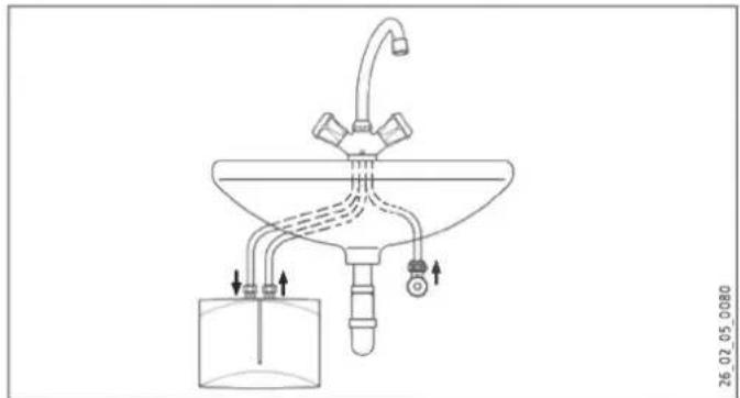
10.2.1 Undersink installation
Non-pressurised, with non-pressurised tap
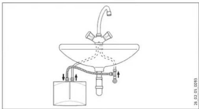
Pressure-tested, with pressure-tested tap
26.02.05.0093
INSTALLATION
Installation
Appliance installation

Note
The wall must have sufficient load bearing capacity.
Mount the appliance on the wall.
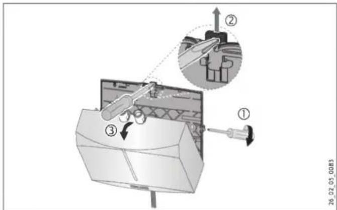
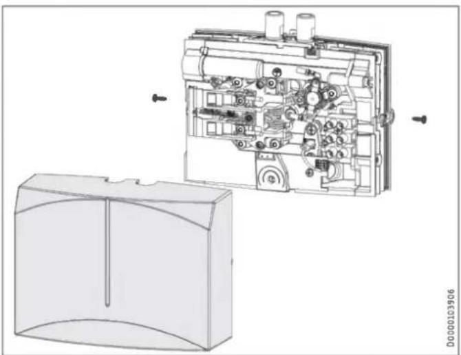
Undo the cover fixing screws by two turns.
Undo the snap fastener using a screwdriver.
- Remove the appliance cover with the heater towards the front.
Using pliers, break out the knock-out for the power cable in the appliance cover. Correct the contours with a file if necessary.
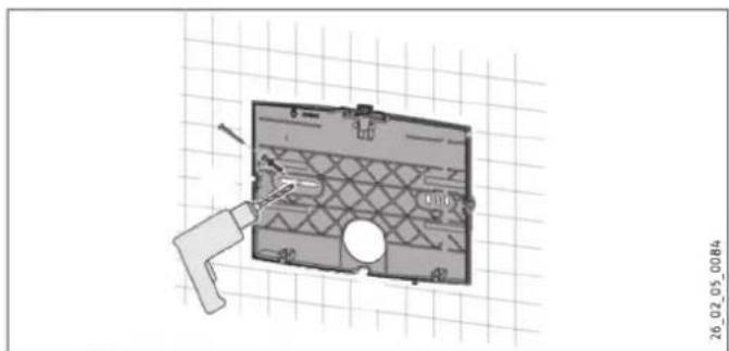
Use the appliance back panel as a drilling template.
- Secure the appliance back panel to the wall with suitable rawl plugs and screws.
INSTALLATION
Installation
- Route the power cable through the knock-out in the back panel.
- Hook in the appliance cover with the heater at the bottom.
- Click the heater into place using the snap fastener.
- Secure the appliance cover with the cover fixing screws.
Tap installation

Property damage
- When making the connections, counterclock the torque on the appliance using a size 14 spanner.
Install the tap. For this, also observe the tap operating and installation instructions.
Pressure-tested tap

Note
Fit the 3/8 connection hose and the 3/8 tee provided.
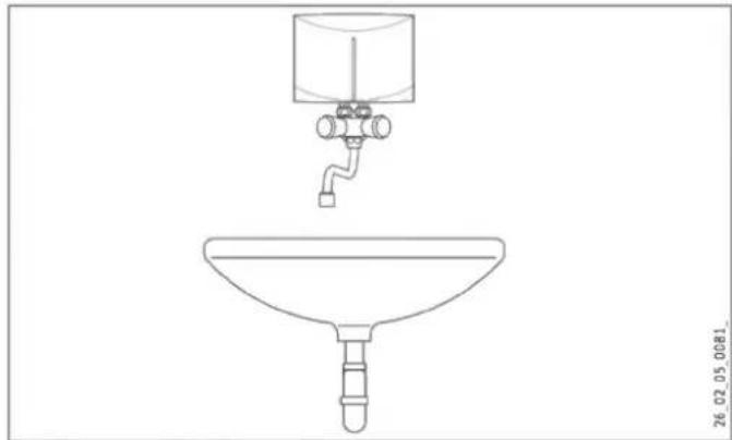
10.2.2 Oversink installation, non-pressurised, with non-pressurised tap
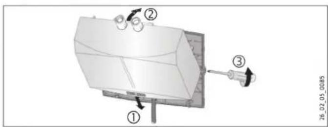
Tap installation

Property damage
When making the connections, counterclock the torque on the appliance using a size 14 spanner.
Install the tap. For this, also observe the tap operating and installation instructions.
Appliance installation
Fit the appliance to the tap with the water connections.
INSTALLATION
Commissioning
10.3 Making the electrical connection

DANGER Electrocution
Carry out all electrical connection and installation work in accordance with relevant regulations.

DANGER Electrocution
Ensure that the appliance is connected to the earth conductor.
Ensure the appliance can be separated from the power supply by an isolator that disconnects all poles with at least 3 mm contact separation.

DANGER Electrocution
The appliances are delivered with a power cable (DEM 3 with plug).
Connection to a permanent power supply is possible, provided the fixed cable has a cross-section that is at least equal to that of the standard power cable of the appliance. The maximum permissible cross-section is 3 × 6 mm^2 .
If the appliance is installed over the sink, route the power cable behind the appliance.

Property damage
When making the connection to a standard safety socket (in the case of a power cable with plug), ensure that the socket is freely accessible after the appliance has been installed.

Property damage
Observe the type plate. The specified voltage must match the mains power supply.
Connect the power cable as shown in the wiring diagram (see chapter "Installation / Specification / Wiring diagram").
11. Commissioning
11.1 Initial start-up
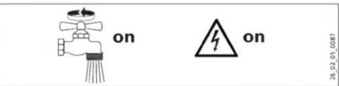
- Fill the appliance for at least one minute by running the tap several times until the pipework and appliance are free of air.
Carry out a tightness check.
INSTALLATION
Commissioning
Insert the power cable plug, if present, into the standard safety socket or set the fuse/MCB.
Check the appliance function.
In the case of oversink installation, affix the company logo supplied over the existing company logo.
11.2 Appliance handover
Explain the appliance function to users and familiarise them with how it works.
Make users aware of potential dangers, especially the risk of scalding.
▶ Hand over these instructions.
11.3 Recommissioning

Property damage
To ensure that the bare wire heating system is not damaged following an interruption to the water supply, the appliance must be recommissioned by taking the following steps.
Isolate the appliance from the power supply across all poles. Pull the power cable plug, if present, from the socket, or remove the fuse/reset the MCB.
- Open and close the tap multiple times for at least one minute until the appliance and the upstream cold water supply line are free of air.
Switch the mains power supply back on again.
11.4 Settings
You can alter the maximum flow rate and temperature.

DANGER Electrocution
The flow rate and temperature may only be adjusted if the appliance is isolated from the power supply.
Isolate all poles of the appliance from the power supply.

DANGER Electrocution
The adjusting screw for changing the flow rate and the potentiometer for setting the temperature are live if the appliance has not been isolated from the power supply.
INSTALLATION
Commissioning
Remove the appliance cover.
Setting the maximum temperature
Factory setting: 38^
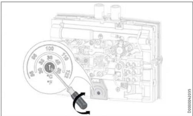
Using a screwdriver, set the potentiometer to the maximum required temperature.
Fit the appliance cover.
INSTALLATION
Shutting down the system
Limiting the flow rate
Factory setting: Maximum flow rate
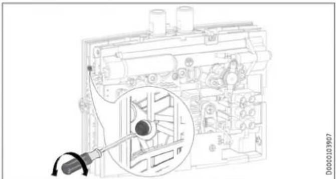
Using the adjusting screw, set the maximum required flow rate:
- Lowest flow rate = wind the screw in as far as it will go.
Maximum flow rate = wind the screw out as far as it will go.
Fit the appliance cover.
12. Shutting down the system
Isolate the appliance from the mains power supply by means of the fuse/MCB in the distribution board or by pulling the power cable plug from the socket.
Drain the appliance (see chapter "Installation / Maintenance").
13. Troubleshooting
| Problem | Cause | Remedy |
| The appliance will not start despite the DHW valve being fully open. | The aerator in the tap is scaled up or dirty. | Clean and/or descale the aerator or replace the special aerator. |
| The flow rate is set too low. | Increase the flow rate. | |
| The strainer in the cold water line is blocked. | Clean the strainer after shutting off the cold water supply line. | |
| The heating system is faulty. | Check the resistance of the heating system and replace the appliance if required. | |
| The safety pressure limit-er has responded. | Remedy the cause of the fault. Isolate the appliance from the power supply and depressurise the water line. Activate the safety pressure limiter. | |
| The preferred tempera-ture is not being reached. The yellow indicator flashes. | The appliance has reached its output limit. | Reduce the flow rate. |
INSTALLATION
Troubleshooting
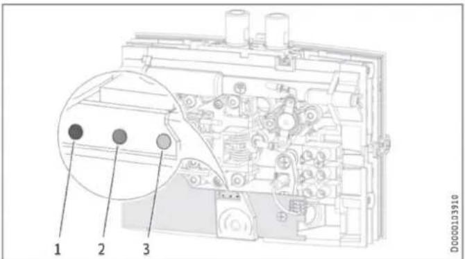
LED indicators
1 Lights up red in the case of a fault
2 Indicator yellow in heating mode / flashing when the output limit is exceeded
3 Flashes green if the PCB is receiving power
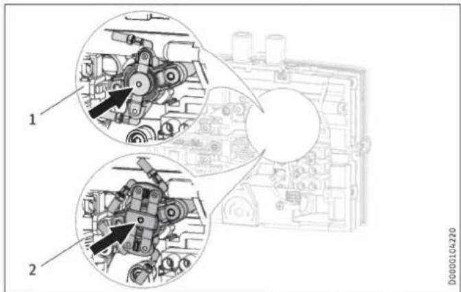
Activating the safety pressure limiter
1 1-pole safety pressure limiter DEM 4 / DEM 6
2 2-pole safety pressure limiter DEM 3 / DEM 7
INSTALLATION
Maintenance
14. Maintenance

DANGER Electrocution
Before any work on the appliance, disconnect all poles from the power supply.
14.1 Draining the appliance

DANGER Scalding
Hot water may escape when you drain the appliance.
If the appliance needs to be drained for maintenance or to protect the whole installation when there is a risk of frost, proceed as follows:
- Close the shut-off valve in the cold water inlet line.
Open the draw-off valve.
Undo the water connections on the appliance.
14.2 Clean the strainer
You can clean the fitted strainer after removing the cold water supply line.
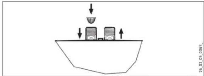
26.02.05.0065
INSTALLATION
Specification
14.3 Tests in accordance with VDE 0701/0702
Earth conductor check
- Check the earth conductor (in Germany e.g. DGUV A3) on the earth conductor contact of the power cable and on the appliance connector.
Insulation resistance
Due to the electronic control of this appliance, an insulation resistance test to VDE 0701/0702 cannot be carried out.
To check the effectiveness of the insulating properties of the appliance, we recommend conducting a residual current test of the earth conductor current / leakage current to VDE 0701/0702 (Fig. C.3b).
14.4 Appliance storage
- Store the dismantled appliance free from the risk of frost, as water residues remaining inside the appliance can freeze and cause damage.
14.5 Replacing the power cable for the DEM 6
If replacing the cable for the DEM 6, use a power cable with 4mm^2 cross-section.
15. Specification
15.1 Dimensions and connections
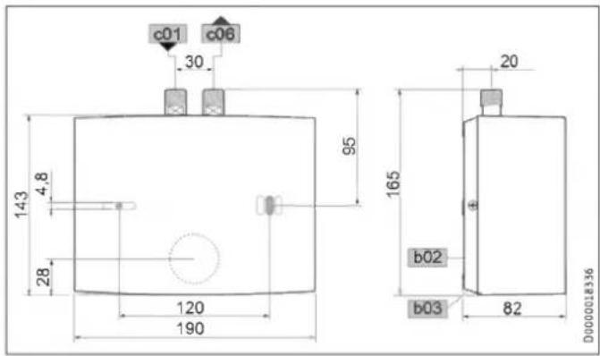
| DEM | |||
| b02 | Entry electrical cables I | ||
| b03 | Entry electrical cables II | ||
| c01 | Cold water inlet | Male thread | G 3/8 A |
| c06 | DHW outlet | Male thread | G 3/8 A |
INSTALLATION
Specification
15.2 Wiring diagram
15.2.1 DEM 3
1/N/PE ~ 200-240 V
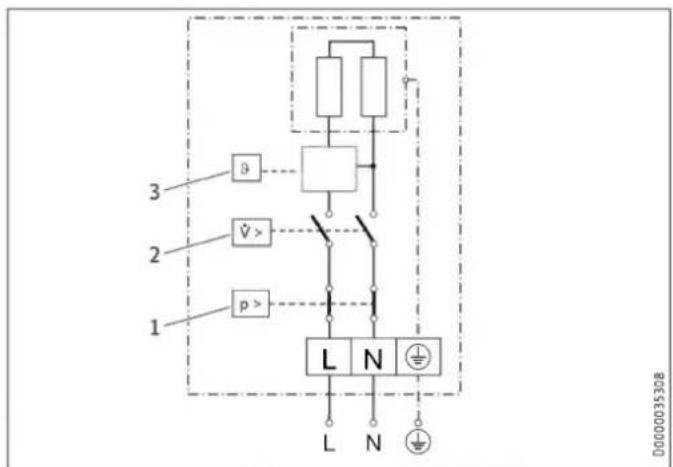
1 Safety pressure limiter
2 Pressure differential switch
3 PCB with outlet temperature sensor
15.2.2 DEM 4 and DEM 6
1/N/PE 200 - 240V
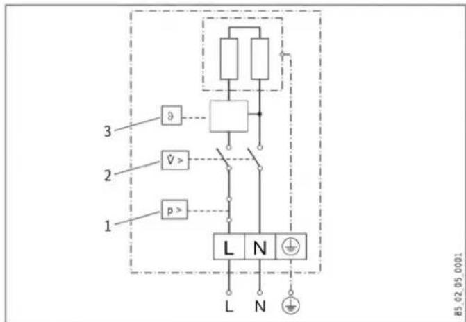
85.02.05.0001
1 Safety pressure limiter
2 Pressure differential switch
3 PCB with outlet temperature sensor
Property damage
In the case of a permanent power supply, connect the power cable according to the designations on the socket terminals.
INSTALLATION
Specification
15.2.3 DEM 7
2/PE 380 - 400V
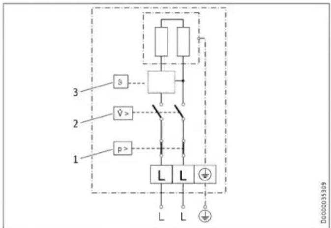
1 Safety pressure limiter
2 Pressure differential switch
3 PCB with outlet temperature sensor
15.3 Temperature increase
At 230V / 400V the following water temperature increases occur:
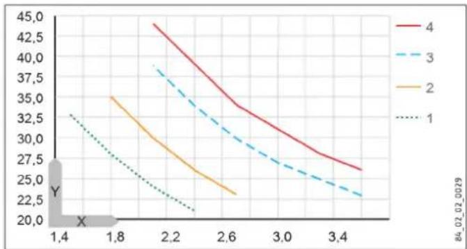
X Flow rate in l/min
Y Temperature increase in K
1 3.5kW - 230V
2 4.4kW - 230V
3 5.7kW - 230V
4 6.5kW - 400V
Example DEM 3 with 3.5kW
| Flow rate | l/min | 2.0 |
| Temperature increase | K | 25 |
| Cold water inlet temperature | °C | 12 |
| Maximum possible outlet temperature | °C | 37 |
INSTALLATION
Specification
15.4 Application areas
Electrical resistivity and electrical conductivity, see "Installation / Specification / Data table"
| Standard specifica- tion at 15 °C | 20 °C | 25 °C | ||||||
| Resis- tivity ρ ≥ | Conductivity σ ≤ | Resis- tivity ρ ≥ | Conductivity σ ≤ | Resis- tivity ρ ≥ | Conductivity σ ≤ | |||
| mS/m | μS/cm | Ω cm | mS/m | μS/cm | Ω cm | mS/m | μS/cm | |
| 1000 | 100 | 1000 | 890 | 112 | 1124 | 815 | 123 | 1227 |
| 1300 | 77 | 769 | 1175 | 85 | 851 | 1072 | 93 | 933 |
15.5 Energy consumption data
Product datasheet: Conventional water heaters to regulation (EU) no. 812/2013 | 814/2013 / (S.I. 2019 No. 539 / Programme 2)
| DEM 3 | DEM 4 | DEM 6 | DEM 7 | |
| 231001 | 231002 | 231215 | 232769 | |
| Manufacturer | STIEBEL ELTRON | STIEBEL ELTRON | STIEBEL ELTRON | STIEBEL ELTRON |
| Load profile | XXS | XXS | XXS | XXS |
| Energy efficiency class | A | A | A | A |
| Energy conversion efficiency | 39 | 39 | 39 | 40 |
| Annual power consumption | kWh | 478 | 478 | 478 |
| Default temperature setting | °C | 38 | 38 | 38 |
| Sound power level | dB(A) | 15 | 15 | 15 |
| Special information on efficiency measurement | none | none | none | none |
| Daily power consumption | kWh | 2.200 | 2.200 | 2.200 |
INSTALLATION
Specification
15.6 Data table
| DEM 3 | DEM 4 | DEM 6 | DEM 7 | ||||||||||||
| 231001 | 231002 | 231215 | 232769 | ||||||||||||
| Electrical data | |||||||||||||||
| Rated voltage | V | 200 | 220 | 230 | 240 | 200 | 220 | 230 | 240 | 200 | 220 | 230 | 240 | 380 | 400 |
| Rated output | kW | 2.7 | 3.2 | 3.53 | 3.8 | 3.3 | 4.0 | 4.4 | 4.8 | 4.3 | 5.2 | 5.7 | 6.2 | 5.9 | 6.5 |
| Rated current | A | 13.3 | 14.5 | 15.2 | 15.8 | 16.7 | 18.2 | 19.1 | 20.0 | 21.6 | 23.6 | 24.7 | 25.8 | 15.5 | 16.3 |
| Fuse protection | A | 16 | 20 | 25 | 25 | 25 | 32 | 16 | 20 | ||||||
| Frequency | Hz | 50/60 | 50/60 | 50/60 | 50/- | ||||||||||
| Phases | 1/N/PE | 1/N/PE | 1/N/PE | 2/PE | |||||||||||
| Resistivity ρ15 ≥ (at θcold ≤25 °C) | Ω cm | 1000 | 1000 | 1000 | 1000 | ||||||||||
| Conductivity σ15 ≤ (at θcold ≤25 °C) | μS/cm | 1000 | 1000 | 1000 | 1000 | ||||||||||
| Resistivity ρ15 ≥ (at θcold ≤50 °C) | Ω cm | 1300 | 1300 | 1300 | 1300 | ||||||||||
| Conductivity σ15 ≤ (at θcold ≤50 °C) | μS/cm | 770 | 770 | 770 | 770 | ||||||||||
| Max. mains impedance at 50 Hz | Ω | 0.091 | 0.083 | 0.079 | 0.076 | 0.072 | 0.065 | 0.063 | 0.06 | 0.056 | 0.051 | 0.049 | 0.047 | 0.236 | 0.225 |
| Connections | |||||||||||||||
| Water connection | G 3/8 A | G 3/8 A | G 3/8 A | G 3/8 A | |||||||||||
| Application limits | |||||||||||||||
| Max. permissible pressure | MPa | 1 | 1 | 1 | 1 | ||||||||||
| Max. inlet temperature for reheating | °C | 50 | 50 | 50 | 50 | ||||||||||
| Values | |||||||||||||||
| Max. permissible inlet temperature | °C | 55 | 55 | 55 | 55 | ||||||||||
| Temperature setting range, DHW | °C | 30-50 | 30-50 | 30-50 | 30-50 | ||||||||||
| On | l/min | >1.5 | >1.8 | >2.2 | >2.2 | ||||||||||
| Pressure drop at flow rate | MPa | 0.05 | 0.06 | 0.07 | 0.07 | ||||||||||
| Flow rate for pressure drop | l/min | 1.5 | 1.8 | 2.2 | 2.2 | ||||||||||
| Flow rate limit at | l/min | 2.0 | 2.2 | 3.2 | 3.2 | ||||||||||
| DHW delivery | l/min | 2.0 | 2.5 | 3.2 | 3.7 | ||||||||||
| Δθ on delivery | K | 25 | 25 | 25 | 25 | ||||||||||
INSTALLATION
Specification
| Hydraulic data | |||||
| DEM 3 | DEM 4 | DEM 6 | DEM 7 | ||
| Nominal capacity | 1 | 0.1 | 0.1 | 0.1 | 0.1 |
| Versions | |||||
| Oversink installation | X | X | X | X | |
| Undersink installation | X | X | X | X | |
| Open vented type | X | X | X | X | |
| Sealed unvented type | X | X | X | X | |
| Protection class | 1 | 1 | 1 | 1 | |
| Insulating block | Plastic | Plastic | Plastic | Plastic | |
| Heating system, heat generator | Bare wire | Bare wire | Bare wire | Bare wire | |
| Cover and back panel | Plastic | Plastic | Plastic | Plastic | |
| Colour | white | white | white | white | |
| IP rating | IP 25 | IP 25 | IP 25 | IP 25 | |
| Dimensions | |||||
| Height | mm | 143 | 143 | 143 | 143 |
| Width | mm | 190 | 190 | 190 | 190 |
| Depth | mm | 82 | 82 | 82 | 82 |
| Length of connecting cable | mm | 700 | 700 | 700 | 700 |
| Weights | |||||
| Weight | kg | 1.5 | 1.5 | 1.5 | 1.5 |

Note
The appliance conforms to IEC 61000-3-12.
Guarantee
The guarantee conditions of our German companies do not apply to appliances acquired outside of Germany. In countries where our subsidiaries sell our products a guarantee can only be issued by those subsidiaries. Such guarantee is only granted if the subsidiary has issued its own terms of guarantee. No other guarantee will be granted.
We shall not provide any guarantee for appliances acquired in countries where we have no subsidiary to sell our products. This will not affect warranties issued by any importers.
Environment and recycling
- Dispose of the appliances and materials after use in accordance with national regulations.
If a crossed-out waste bin is pictured on the appliance, take the appliance to your local waste and recycling centre or nearest retail take-back point for reuse and recycling.
This document is made of recyclable paper.
PAP
Dispose of the document at the end of the appliance's life cycle in accordance with national regulations.
REMARQUESPARTICULIERES
UTILISATION
Comfort through Technology

- BESONDEREHINWEISE
- INSTALLATION
- Sicherheit
- Sicherheit
- X Volumenstrom in l/min
- GUARANTEE
- ENVIRONMENT AND RECYCLING
- SPECIAL INFORMATION
- OPERATION
- General information
- General information
- Note
- Safety instructions
- Structure of safety instructions
- SIGNAL WORD Type of risk
- Symbols, type of risk
- Signal words
- Safety
- Other symbols in this documentation
- Units of measurement
- Safety
- Intended use
- General safety instructions
- DANGER Burns
- Appliance description
- WARNING Injury
- DANGER Electrocution
- Property damage
- Test mark
- Appliance description
- Settings
- Settings
- Increasing the temperature
- Reducing the temperature
- Following an interruption of the water supply
- Cleaning, care and maintenance
- Troubleshooting
- Safety
- General safety instructions
- WARNING Electrocution
- Instructions, standards and regulations
- Appliance description
- Standard delivery
- Preparation
- Accessories
- Special aerator
- Non-pressurised taps
- Pressure-tested tap
- Preparation
- Water installation
- Taps
- Installation
- Installation site
- Installation alternatives
- Undersink installation
- Appliance installation
- Tap installation
- Oversink installation, non-pressurised, with non-pressurised tap
- Commissioning
- Making the electrical connection
- Commissioning
- Initial start-up
- Appliance handover
- Recommissioning
- Settings
- Setting the maximum temperature
- Shutting down the system
- Limiting the flow rate
- Shutting down the system
- Troubleshooting
- Troubleshooting
- Maintenance
- Maintenance
- Draining the appliance
- Clean the strainer
- Specification
- Tests in accordance with VDE 0701/0702
- Earth conductor check
- Insulation resistance
- Appliance storage
- Replacing the power cable for the DEM 6
- Specification
- Dimensions and connections
- Wiring diagram
- DEM 3
- DEM 4 and DEM 6
- DEM 7
- Temperature increase
- Application areas
- Energy consumption data
- REMARQUESPARTICULIERES
- UTILISATION
Brand : STIEBEL ELTRON
Model : DEM
Category : Boiler