DHE 18/21/24 - Boiler STIEBEL ELTRON - Free user manual and instructions
Find the device manual for free DHE 18/21/24 STIEBEL ELTRON in PDF.
| Product type | Electric instantaneous water heater |
| Brand | Stiebel Eltron |
| Model | DHE 18/21/24 (adjustable 18/21/24 kW) |
| Dimensions (H x W x D) | 466 x 225 x 116 mm |
| Weight | 3.1 kg |
| Power supply | 3/PE ~380-415 V, 50/60 Hz |
| Connected load | 18 / 21 / 24 kW (selectable via jumper) |
| Temperature range | OFF, 20 °C to 60 °C (in 0.5 °C increments) |
| Protection rating | IP 25 (IP 24 in horizontal installation) |
| Maximum admissible pressure | 1 MPa (10 bar) |
| Maximum incoming water temperature | 55 °C (supplementary heating), 70 °C max. (disinfection) |
| Starting flow rate | > 2.5 l/min |
| Nominal capacity | 0.4 l |
| Protection class | 1 |
| Housing material | Synthetic materials |
| Color | White |
| Main functions | Electronic regulation, motorized valve, ECO function (3 levels), Tmax limitation, wellness shower programs (4), automatic quantity regulation, consumption display, temperature memory, control lock |
| Safety | Internal anti-scald protection (adjustable by installer), safety limiter, safety switch, air detection |
| Cleaning and maintenance | Cleaning with damp cloth, descaling of aerators, cleaning of cold water inlet filter |
| Spare parts and repairability | Functional modules, sensors, motorized valve, control unit, safety limiter, flow sensor; accessories: radio remote control, load shedding relay, thermostatic mixer, mounting kits |
| General information | Domestic use, can supply several draw-off points, suitable for shower (shower mode with limitation to 55 °C), vertical or horizontal installation, CE compliant |
Frequently Asked Questions - DHE 18/21/24 STIEBEL ELTRON
User questions about DHE 18/21/24 STIEBEL ELTRON
0 question about this device. Answer the ones you know or ask your own.
Ask a new question about this device
Download the instructions for your Boiler in PDF format for free! Find your manual DHE 18/21/24 - STIEBEL ELTRON and take your electronic device back in hand. On this page are published all the documents necessary for the use of your device. DHE 18/21/24 by STIEBEL ELTRON.
USER MANUAL DHE 18/21/24 STIEBEL ELTRON
20^ 60^ 0,5^ 68^ F... 140^ 1^
text_image
Diagram illustrating a mechanical or fluid system with labeled components and directional arrows, including an inset showing a device with text 'IN EXCESS EXCESS' and a magnified view.D0000053312
BEDIENUNG | INSTALLATION
text_image
QR code image containing encoded data, no visible human-readable textwww.stiebel-eltron.com/registration
INSTALLATION
8. Sicherheit
text_image
Diagram showing three stages of a mechanical device with labeled parts and directional arrows indicating motion or assembly.natural_image
Mechanical assembly diagram showing two views of a mechanical component with no visible text or symbolsnatural_image
Technical diagram of a mechanical component with mounting holes and mounting points, displayed on grid paper (no text or symbols)text_image
Diagram showing a mechanical assembly with labeled parts 1 and 2, indicating a step in operation.natural_image
Technical illustration of a mechanical assembly with two circular insets showing close-ups of components (no text or symbols)D0000053274
natural_image
Diagram showing a refrigerator with a close-up view of the interior air conditioner unit (no text or symbols present)D0000073198
natural_image
Three sequential diagrams showing a mechanical device with a spring and a hanging weight, no text or symbols present.D0000053280
natural_image
Mechanical component diagram with mounting holes and a central pin (no text or symbols)text_image
Diagram showing a door lock mechanism with directional arrows and a magnified inset view of the lock structure.
text_image
Diagram showing a device connected to two labeled devices, one with an arrow indicating connection or measurement.D0000073012
natural_image
Architectural floor plan showing room layouts and equipment layout (no text or labels)1.1 Safety instructions 59
1.2 Other symbols in this documentation 60
1.3 Units of measurement 60
- Safety 61
2.1 Intended use 61
2.2 General safety instructions 61
2.3 Test symbols 62
2.4 EU Declaration of Conformity 62
-
Appliance description 62
-
Settings and displays 63
4.1 User interface 63
4.2 Display symbols 64
4.3 Selecting the set temperature 64
4.4 Temperature limit via internal anti-scalding protection (qualified contractor) 65
4.5 Temperature limit Tmax (user) 65
4.6 Assigning temperature memory buttons 65
4.7 Inlet temperature information 65
4.8 Info menu 65
4.9 Settings in the parameter menu 66
4.10 Recommended settings 70
- Cleaning, care and maintenance 70
- Troubleshooting 71
INSTALLATION
- Safety 72
7.1 General safety instructions 72
7.2 Shower operation 72
7.3 Instructions, standards and regulations 72 - Appliance description 73
8.1 Standard delivery 73
8.2 Accessories 73 - Preparation 74
9.1 Installation site 74
9.2 Minimum clearances 75
9.3 Water installation 75 - Installation 76
10.1 Standard installation 76 - Commissioning 81
11.1 Preparation 81
11.2 Initial start-up 82
11.3 Recommissioning 84 - Appliance shutdown 84
- Installation alternatives 84
13.1 Electrical connection from above on unfinished walls_85
CONTENTS
13.2 Electrical connection on unfinished walls from below with short power cable 86
13.3 Electrical connection on finished walls 86
13.4 Connecting a load shedding relay 87
13.5 Water installation on finished walls 87
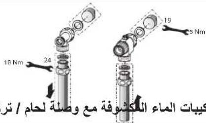
13.6 Water installation on finished walls with solder/press fittings 88
13.7 Fitting appliance cover for water installation on finished walls 88
13.8 Lower back panel section installation with threaded fittings on finished walls 89
13.9 Wall mounting bracket when replacing an appliance_90
13.10 Installation with offset tiles 90
13.11 Rotated appliance cover 91
13.12 Operation with preheated water 91
13.13 Horizontal installation of the appliance 92
-
Service information 93
-
Troubleshooting 94
15.1 Fault code display 96
-
Maintenance 97
-
Specification 98
17.1 Dimensions and connections 98
17.2 Wiring diagram 99
17.3 DHW output 100
17.4 Application areas / conversion table ____ 100
17.5 Pressure drop 101
17.6 Fault conditions 101
17.7 Energy consumption data 101
17.8 Data table 102
GUARANTEE
ENVIRONMENT AND RECYCLING
SPECIAL INFORMATION
- The appliance may be used by children over 3 years of age and persons with reduced physical, sensory or mental capabilities or a lack of experience and expertise, provided that they are supervised or they have been instructed on how to use the appliance safely and have understood the potential risks. Children must never play with the appliance. Cleaning and user maintenance must not be carried out by children without supervision.
-
During operation, the tap can reach temperatures up to 70 °C. There is a risk of scalding at outlet temperatures in excess of 43 °C.
-
The appliance is suitable for supplying a shower (shower operation). If the appliance is also or exclusively used for shower operation, the qualified contractor must adjust the temperature setting range to 55 °C or less using the internal anti-scalding protection on the appliance. When using preheated water, ensure that the inlet temperature does not exceed 55 °C.
- Ensure the appliance can be separated from the power supply by an isolator that disconnects all poles with at least 3 mm contact separation.
- The specified voltage must match the power supply.
- The appliance must be connected to the earth conductor.
OPERATION
General information
- The appliance must be permanently connected to fixed wiring.
- Secure the appliance as described in chapter "Installation / Installation".
- Observe the maximum permissible pressure (see chapter "Installation / Specification / Data table").
- The specific water resistivity of the mains water supply must not be undershot (see chapter "Installation / Specification / Data table").
- Drain the appliance as described in chapter "Installation / Maintenance / Draining the appliance".
OPERATION
1. General information
The chapters "Special information" and "Operation" are intended for both users and qualified contractors.
The chapter "Installation" is intended for qualified contractors.

Note
Read these instructions carefully before using the appliance and retain them for future reference.
Pass on these instructions to a new user if required.
1.1 Safety instructions
1.1.1 Structure of safety instructions

KEYWORD Type of risk
Here, possible consequences are listed that may result from failure to observe the safety instructions.
▶ Steps to prevent the risk are listed.
OPERATION
General information
1.1.2 Symbols, type of risk
Symbol Type of risk

Injury

Electrocution

Burns (burns, scalding)
1.1.3 Keywords
KEYWORD Meaning
DANGER Failure to observe this information will result in serious injury or death.
WARNING Failure to observe this information may result in serious injury or death.
CAUTION Failure to observe this information may result in non-serious or minor injury.
1.2 Other symbols in this documentation

Note
General information is identified by the adjacent symbol. ▶ Read these texts carefully.
Symbol Meaning

Material losses
(appliance damage, consequential losses and environmental pollution)

Appliance disposal
This symbol indicates that you have to do something. The action you need to take is described step by step.
1.3 Units of measurement

Note
All measurements are given in mm unless otherwise stated.
OPERATION
Safety
2. Safety
2.1 Intended use
This appliance is suitable for heating domestic hot water or for reheating preheated water. The appliance can supply one or more draw-off points.
Water will not be reheated if the maximum inlet temperature for reheating is exceeded.
The appliance is intended for domestic use. It can be used safely by untrained persons. The appliance can also be used in non-domestic environments, e.g. in small businesses, as long as it is used in the same way.
Any other use beyond that described shall be deemed inappropriate. Observation of these instructions and of the instructions for any accessories used is also part of the correct use of this appliance.
2.2 General safety instructions

CAUTION Burns
During operation, the tap can reach temperatures up to 70 °C. There is a risk of scalding at outlet temperatures in excess of 43 °C.

CAUTION Burns
If children or persons with limited physical, sensory or mental capabilities use the appliance, set a temperature limit. Once set, check the temperature limit is working correctly.
If a permanent and unchangeable temperature limit is required, have the internal anti-scalding protection set by a qualified contractor.

CAUTION Burns
If operating with preheated water, e.g. if using a solar thermal system, observe the following information:
- The DHW temperature may exceed the set temperature or a set temperature limit.
- The dynamic anti-scalding protection between the appliance and a wireless remote control may not be effective.
▶ In such cases, limit the temperature with an upstream central thermostatic valve (e.g. ZTA 3/4).
OPERATION
Appliance description

WARNING Injury
The appliance may be used by children over 3 years of age and persons with reduced physical, sensory or mental capabilities or a lack of experience and expertise, provided that they are supervised or they have been instructed on how to use the appliance safely and have understood the potential risks. Children must never play with the appliance. Cleaning and user maintenance must not be carried out by children without supervision.

Material losses
The user should protect the appliance and its tap against frost.
2.3 Test symbols
See type plate on the appliance.
2.4 EU Declaration of Conformity

Note
DHE: STIEBEL ELTRON hereby declares that the radio equipment type complies with Directive 2014/53/EU. The full text of the EU Declaration of Conformity can be found at the following internet address: www.stiebel-eltron.de/downloads
3. Appliance description
The appliance switches on automatically as soon as you open the hot water valve on the tap. When you close the tap, the appliance switches off again automatically.
The appliance heats water as it flows through it. The set temperature is adjustable. Upwards of a certain flow rate, the control unit selects the required heating output, subject to the temperature selected and the cold water temperature.
The instantaneous water heater with full electronic control and automatic output matching maintains a consistent outlet temperature. The fully electronic control unit with motorised valve ensures the water is accurately heated to the selected temperature. This occurs regardless of the inlet temperature.
If the appliance is operated with preheated water and the inlet temperature exceeds the selected temperature, the inlet temperature is indicated on the second display line and flashes. The water is not heated further.
You can store different set temperatures and call them up quickly. In the ECO function, the integral motorised valve limits the flow rate to 3 preset levels. The appliance has setting options for a temperature limit (Tmax function, user) and internal anti-scaling protection (qualified contractor). The backlight switches on automatically as soon as water starts to flow through the appliance or you make a change on the user interface. The backlight switches off automatically after water stops flowing or if no action is performed.
OPERATION
Settings and displays
Heating system
The bare wire heating system is enclosed within a pressure-tested plastic jacket. The heating system with its stainless steel heater spiral is suitable for hard and soft water areas and is largely in-susceptible to scale build-up. The heating system ensures rapid and efficient DHW provision.

Note
The appliance is equipped with an air detector that largely prevents damage to the heating system. If, during operation, air is drawn into the appliance, the appliance shuts down heating output for one minute to protect the heating system.
4. Settings and displays
4.1 User interface
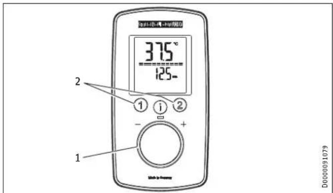
text_image
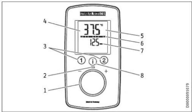
375° 125- 4 3 1 2 + 1 5 6 7 8 D00000910791 Selector
2 ON LED
3 Temperature memory keys
4 Backlit display
5 Main display | info display | parameter display
6 Segment display [10 - 100 %]
7 Second display line
8 "i" button to call up information and select menus
OPERATION
Settings and displays
4.2 Display symbols
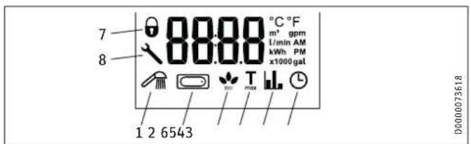
The symbols are shown on the display when activated.
text_image
7 8 80.00 °C °F m² gpm 1/min AM kWh PM x1000 gal 1 2 6543 D0000736181 Wellness showers
2 Automatic water volume control
3 ECO display
4 Tmax, displayed when temperature limit is enabled
5 Consumption indicator
6 Time
7 Operating lock [ON / OFF]
8 Spanner symbol, appears in the event of a fault
4.3 Selecting the set temperature
text_image
375°C 125- ① ② ① ① - + 1 D0000910791 Set temperature settings: OFF, 20 - 60 °C
2 To call up/assign preferred temperatures
Settings
Setting Step Setting Step
20 °C ... 60 °C 0.5 °C 68 °F ... 140 °F
1°F
D000091079
4.4 Temperature limit via internal anti-scalding protection (qualified contractor)
If required, the qualified contractor can set a permanent temperature limit, for example in nurseries, hospitals, etc.
OPERATION
Settings and displays
When supplying a shower, the appliance temperature setting range must be adjusted by the qualified contractor to 55 °C or less. If the anti-scalding protection function is enabled and the temperature limit is reached, "Tmax" flashes.
4.5 Temperature limit Tmax (user)
You can adjust the temperature limit individually. If the temperature limit is enabled, "Tmax" is shown on the display.
4.5.1 Activating/deactivating the temperature limit Tmax
See chapter "Settings in the parameter menu".
4.6 Assigning temperature memory buttons
Memory buttons "1" and "2" can each be assigned a preferred temperature.
▶ Select the preferred temperature.
▶ To save the preferred temperature, press and hold button "1" or "2" for more than 3 seconds. The selected temperature flashes once to confirm.
4.7 Inlet temperature information
If the appliance is operated with preheated water and the inlet temperature exceeds the selected set temperature, the inlet temperature is indicated on the second display line and flashes. The water is not heated further.
4.8 Info menu
The appliance has an additional display where consumption values can be shown.
4.8.1 Calling up the info menu
▶ Briefly press "i" until "i 1" appears, then continue to press "i" to see further menus.
▶ Exit the menu item by pressing "i" and holding for more 5 seconds. Alternatively: The system exits the menu item automatically 30 seconds after the setting has been completed.
| Menu | Description | Explanations | Screen | display |
| 1 1 | Flow rate The current flow rate is shown. | flow rate is shown. | Flow rate in l/min or gpm |
| 1 2 | Time The current time is shown. | The current time is shown. | Time |
| 1 3 | Energy consumption The amount of energy consumed is shown. | The amount of energy consumed is shown. | Value in kWh |
| 1 4 | Water consumption The amount of water consumed is shown. | The amount of water consumed is shown. | Value in m^3 or gal |

Note
The consumption values are calculated starting from the last reset.
OPERATION
Settings and displays
4.9 Settings in the parameter menu
4.9.1 Activating the parameter menu
▶ Briefly press and hold "i" for more than 5 seconds until "P 1" appears, then continue by briefly pressing "i".
▶ In the selected parameter menu, turn the temperature selector to the required display / setting.
4.9.2 Parameter menu
| Menu | Description Selectable display | setting | Explanations Symbol | | display | |
| P 1 | ECO water and energy saving function | OFF | ECO1 | ECO2 | ECO3 | The ECO function enables you to limit the flow rate to a maximum value. Flow rate limit:8 l/min with "ECO1" | 7 l/min with "ECO2" | 6 l/min with "ECO3" | No flow rate limit with "OFF". | |
| P 2 | Temperature limit Tmax | OFF | 20.0 | 20.5 ... °C or 68 | 69 ... °F | The temperature limit allows you as a user to restrict the adjustable set temperature at the appliance to a maximum value. Check that the upper temperature limit has been correctly applied. Your qualified contractor can set an additional temperature limit for anti-scalding protection. This temperature then dictates the upper limit of the setting range for the temperature limit function. | Tmax |
OPERATION
Settings and displays
| Menu | Description Selectable display | setting | Explanation Symbol | | display |
| P 3 | Wellness showers | OFF | Pro1 | Pro2 | Pro3 | Pro4 | The Wellness shower program lets you choose from 4 different alternating shower programs.WW = domestic hot water, KW = cold water, min = minutes, sec = seconds- 1 Cold preventionTo strengthen the body, we recommend finishing off with a cold shower; this will trigger a reflex in the body to warm up.____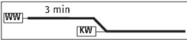 - 2 Winter refreshmentAn invigorating end to a winter shower with a final warm-up.____ - 2 Winter refreshmentAn invigorating end to a winter shower with a final warm-up.____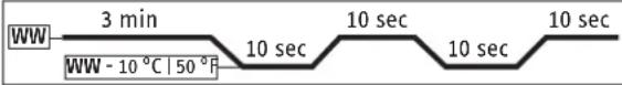 - 3 Summer fitness programA quick contrast shower to increase fitness with a final warm-up.____ - 3 Summer fitness programA quick contrast shower to increase fitness with a final warm-up.____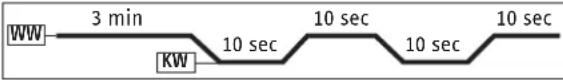 - 4 Circulation boost programShower your arms and legs with cold water to boost circulation. Spray from the hands and feet towards the body. You can then repeat this process with hot water.____ - 4 Circulation boost programShower your arms and legs with cold water to boost circulation. Spray from the hands and feet towards the body. You can then repeat this process with hot water.____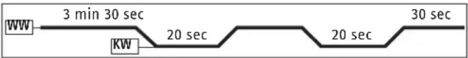 |
OPERATION
Settings and displays
| Menu | Description Selectable display | setting | Explanations Symbol | | display | |
| P 4 | Automatic water volume control - set the volume in the selected unit | OFF | 5 | 10 | ... 200 | or 2 ... 52 gal | With the automatic water volume control, you can preselect a volume of water, e.g. for filling a bathtub. When the preselected water volume is reached, the automatic control reduces the flow rate. The automatic water volume control must be enabled on each occasion prior to filling the bath.Example, filling a bath with 80 litres (21 gallons): When the bath has been filled with 80 litres (21 gallons), the control automatically reduces the flow rate to 4 l/min (1 gpm). | |
| P 5 | Temperature unit | C | F | Select the temperature unit for all settings. | °C | °F |
| P 6 Volume unit L | GAL Select the volume unit for all settings. | | gal | ||||
| P 7 Time format 24h | 12h | Select time format. | ◎ | ||
| P 8 | Time setting | ---:-- | You can set the time using the 12 or 24 hour clock:- 12 hours from 00:00 - 11:59 = AM | 11:59 - 00:00 = PM- 24 hours from 00:00 to 23:59After a power cut, the time needs to be set again. | AM | PM (only for 12h) |
| P 9 | Operating lock | ON | OFF | You can set the operating lock to "ON" or "OFF".To disable the set operating lock:► Press and hold "i" for more than 12 seconds. | ◎ (only when ON) |
| P 10 | Reset to factory settings | Reset (rSEt) | You can restore the appliance to its factory settings. "rSEt" is shown on the display.► Press "1" and "2" simultaneously and hold for longer than 5 seconds. The display switches to "On" to confirm the reset.► To confirm "On", press and hold "i" for more than 5 seconds. | |
| P 11 | Resetting the consumption values | Reset (rSEt | □) | You can reset the consumption values. "rSEt" is shown on the display.► Press "1" and "2" simultaneously and hold for longer than 5 seconds. The display switches to "On" to confirm the reset.► To confirm "On", press and hold "i" for more than 5 seconds. | |
OPERATION
Settings and displays
| Menu | Description Selectable display | setting | Explanations Symbol | | display | |
| P 12 | Backlighting | Auto | On | You can adjust the display backlight.- If "Auto" is selected, the backlight is switched on during heating operation and each time an action is performed. If no action is performed for 30 seconds, the backlight is switched off again.- If you select "On", the backlight will remain on constantly. | |
| P 13 | Reduce backlighting 100 % | | 20 % ( ) You can select 2 levels of brightness for the backlight. | ||
| P 14 | Wireless module | After installation of a wireless module (with or without paired wireless remote control) in the appliance, menu item P 14 is enabled and "rc" appears on the programming unit display. You can pair one or more wireless remote controls; to do so, follow the pairing procedure on the appliance and the wireless remote control.Pressing "1" on the appliance for longer than 5 seconds starts the pairing process, which is shown on the programming unit of the appliance by a progress bar on the display and the operating LED flashing. Start the pairing process on the wireless remote control as described in the relevant operating instructions. After successful pairing, the operating LED on the appliance flashes briefly. An unsuccessful pairing attempt is automatically terminated after 30 seconds.Pressing "2" on the appliance for longer than 5 seconds unpairs all connected wireless remote controls. During unpairing, "rc0" appears on the display of the programming unit for 5 seconds, then "rc" again. | ||
4.9.3 Deactivating the parameter menu
▶ Exit the menu item by pressing "i" and holding for more than 5 seconds. Alternatively: The system exits the menu item automatically 30 seconds after the setting has been completed.
OPERATION
Cleaning, care and maintenance
4.10 Recommended settings
Your instantaneous water heater offers maximum precision and maximum convenience in DHW provision. Should you nonetheless operate the appliance with a thermostatic valve, we recommend that you:
▶ Adjust the set temperature on the appliance to over 50 °C. Then set the required set temperature on the thermostatic valve.
Saving energy
The following recommended settings will result in the lowest energy consumption:
- 38 °C for hand washbasins, showers, bath
- 55 °C for kitchen sinks
Internal anti-scalding protection (qualified contractors)
If required, the qualified contractor can set a permanent temperature limit, for example in nurseries, hospitals, etc.
Recommended setting for operation with a thermostatic valve and water preheated by solar energy
▶ Set the temperature at the appliance to the maximum temperature.
Following an interruption to the water supply

Material losses
To ensure that the bare wire heating system is not damaged following an interruption to the water supply, the appliance must be recommissioned by taking the following steps.
▶ Disconnect the appliance from the power supply by removing the fuses/tripping the MCBs.
▶ Open the tap for one minute until the appliance and its upstream cold water inlet line are free of air.
▶ Switch on the power supply again.
5. Cleaning, care and maintenance
▶ Never use abrasive or corrosive cleaning agents. A damp cloth is sufficient for cleaning the appliance.
▶ Check the taps regularly. Limescale deposits at the tap outlets can be removed using commercially available descaling agents.
OPERATION
Troubleshooting
- Troubleshooting
| Problem Cause Remedy | ||
| The appliance will not start despite the DHW valve being fully open. | There is no power. | Check the fuses / MCBs in your fuse box / distribution board. |
| The aerator in the tap or the shower head is scaled up or dirty. | Clean and/or descale the aerator or shower head. | |
| The water supply has | been interrupted. | Vent the appliance and the cold water inlet line. |
| When hot water is being drawn off, cold water flows for a short period. | The air sensor is detecting air in the water. It briefly switches off the heating output. | The appliance restarts automatically after 1 minute. |
| The required temperature cannot be set. | The high limit safety cut-out and/or internal anti-scalding protection are enabled. | Deactivate the temperature limit. The internal anti-scalding protection can only be adjusted by qualified contractors. |
| The flow rate is too low. | ECO function is enabled. | Select a different ECO level or disable the ECO function. |
| No settings can be made on the programming unit. | The operating lock is enabled. | To deactivate the operating lock, press the "i" button for more than 12 seconds. |

Note
Programming unit displays and selected settings are retained following a power failure.
If you cannot remedy the fault, contact your qualified contractor. To facilitate and speed up your enquiry, please provide the serial number from the type plate (000000-0000-000000).
text_image
Diagram illustrating a mechanical assembly or lifting process with labeled components and an inset detail view showing a component with text 'B1.00234605.0000'.D0000053312
INSTALLATION
Safety
INSTALLATION
7. Safety
Only a qualified contractor should carry out installation, commissioning, maintenance and repair of the appliance.
7.1 General safety instructions
We guarantee trouble-free function and operational reliability only if original accessories and spare parts intended for the appliance are used.

Material losses
Observe the maximum inlet temperature. Higher temperatures may damage the appliance. You can limit the maximum inlet temperature by installing a central thermostatic valve (see chapter "Appliance description / Accessories").

WARNING Electrocution
This appliance contains capacitors which are discharged when disconnected from the power supply. The capacitor discharge voltage may briefly exceed 60 V DC.
7.2 Shower operation

CAUTION Burns
▶ When supplying a shower, set the internal anti-scalding protection to 55 °C or less; see chapter "Commissioning / Preparations".

CAUTION Burns
If operating with preheated water, e.g. if using a solar thermal system, observe the following information:
- The DHW temperature may exceed the set temperature or a set temperature limit.
- The dynamic anti-scalding protection between the appliance and a wireless remote control may not be effective.
▶ In such cases, limit the temperature with an upstream central thermostatic valve (e.g. ZTA 3/4).
7.3 Instructions, standards and regulations

Note
Observe all applicable national and regional regulations and instructions.
- The IP 24 / IP 25 protection rating can only be ensured with a correctly fitted cable grommet.
INSTALLATION
Appliance description
- The electrical resistivity of the water must not fall below that stated on the type plate. In a linked water network, take into consideration the lowest electrical resistivity of the water. Your water supply utility will advise you of the electrical resistivity or conductivity of the water in your area.
8. Appliance description
8.1 Standard delivery
The following are delivered with the appliance:
- Wall mounting bracket
- Installation template
- 2 twin nipples
- 3-way ball shut-off valve for cold water
- Tee for domestic hot water
- Flat gaskets
- Strainer
- Plastic profile washer
- Plastic connection pieces / installation aid
- Cover and back panel guides
- Jumper for internal anti-scalding protection
- Jumper for output changeover (only with DHE 18/21/24)
8.2 Accessories
Wireless remote control
- FFB 4 Set EU
Fittings
- MEKD mono lever kitchen pressure tap
- MEBD mono lever bath pressure tap
Water plugs G 12 A
If you use taps other than the recommended pressure taps on finished walls, please use the plugs.
Installation set for finished walls
- Solder fitting - copper pipe for soldered connection ∅ 12 mm
- Press fitting - copper pipe
- Press fitting – plastic pipe (suitable for Viega: Sanfix-Plus or Sanfix-Fosta)
Universal mounting frame
- Mounting frame with electrical connections
Pipe assembly for undersink appliances
You will need the undersink installation set if you make the water connections (G 38 A) at the top of the appliance.
INSTALLATION
Preparation
Pipe assembly for offset installation
Use this pipe assembly if you intend to offset the appliance by up to 90 mm downwards from the water connection.
Pipe assembly for replacing a gas water heater
You will need this pipe assembly set if the existing installation has gas water heater connections (cold water connection on the left-hand side, DHW connection on the right-hand side).
Pipe assembly for DHB water plug-in couplings
Use the water plug-in couplings if the existing installation contains water plug-in connections from a DHB water heater.
Load shedding relay (LR 1-A)
The load shedding relay for installation in the distribution board provides priority control for the instantaneous water heater when other appliances, such as electric storage heaters, are being operated simultaneously.
Central thermostatic valve (ZTA 3/4)
Use the thermostatic valve for central premixing, for example when operating an instantaneous water heater with preheated water. For use in shower operation, the valve must be set to a maximum of 55 °C.
9. Preparation
9.1 Installation site

Material losses
Install the appliance in a room that is free from the risk of frost.
▶ Always install the appliance vertically and near the draw-off point. For horizontal installation, see chapter "Installation alternatives / Horizontal installation of the appliance".
The appliance is suitable for undersink and oversink installation.
Undersink installation
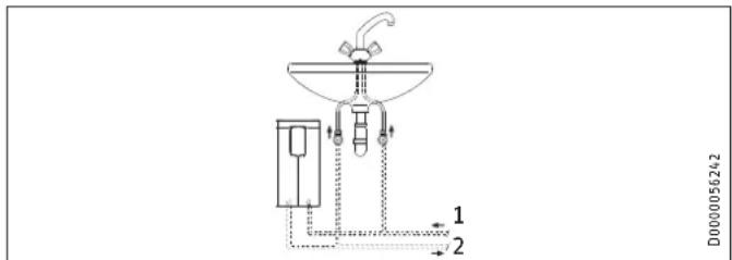
text_image
D0000056242 1 2Oversink installation
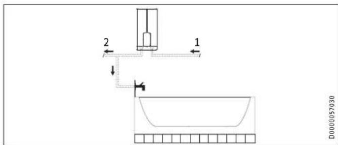
text_image
2 1 D0000057030▶ Mount the appliance on the wall. The wall must have sufficient load bearing capacity.
9.2 Minimum clearances
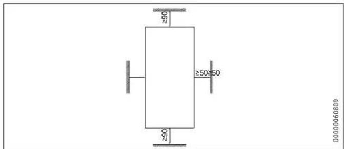
text_image
≥60 ≥50≥50 ≥60 D0000060809- Maintain the minimum clearances to ensure trouble-free operation of the appliance and facilitate maintenance work.
9.3 Water installation
▶ Flush the water line thoroughly.
Fittings
Use appropriate pressure taps. Open vented taps are not permissible.

Note
Never use the 3-way ball shut-off valve in the cold water inlet to reduce the flow rate. The 3-way ball shut-off valve is intended only to shut off the cold water inlet.
INSTALLATION
Installation
Permissible water line materials
- Cold water inlet line:
Pipes made from galvanised steel, stainless steel, copper or plastic - DHW outlet line:
Pipes made from stainless steel, copper or plastic

Material losses
If plastic pipework systems are used, take into account the maximum inlet temperature and the maximum permissible pressure.
Flow rate
▶ Ensure that the flow rate for switching on the appliance is achieved.
▶ If the required flow rate is not achieved when the draw-off valve is fully open, increase the water line pressure.
10. Installation
| Factory settings DHE 18/21/24 DHE 27 | |||
| Internal anti-scalding protection °C 60 60 | |||
| Connected load | kW | 21 | 27 |
| Adjustable connected load | x | - | |
| Standard installation | DHE 18/21/24 | DHE 27 |
| Electrical connection from below on unfinished walls | x | x |
| Water connection on unfinished walls | x | x |
For further installation options, see chapter "Alternative installation methods".
10.1 Standard installation
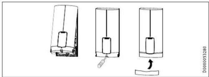
Opening the appliance
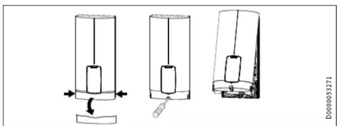
text_image
Diagram showing three stages of a mechanical device with labeled parts and directional arrows indicating motion or assembly.INSTALLATION
Installation
▶ Open the appliance by holding the fascia at the side and puRitting the wall mounting bracket
ing forwards away from the appliance cover. Undo the screw.
Pivot open the appliance cover.
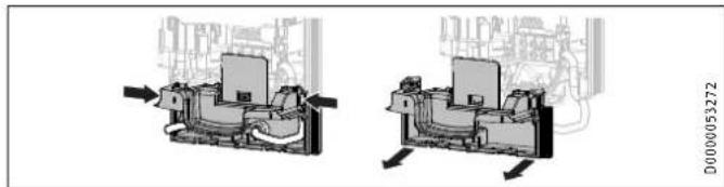
natural_image
Mechanical assembly diagram showing two views of a device with internal components and directional arrows (no text or symbols)▶ Remove the back panel by pressing the two locking tabs and pulling the lower back panel section forwards.
Preparing the power cable on unfinished walls, for connection from below
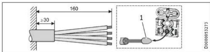
text_image
160 ≥30 1 D0000532731 Cable entry installation aid
▶ Prepare the power cable.
natural_image
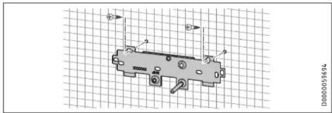
Technical diagram of a mechanical component with mounting holes and internal features, displayed on grid paper (no text or symbols)Mark out the holes for drilling using the installation template. If the appliance is to be installed on finished walls, also mark out the fixing hole in the lower section of the template.
▶ Drill the holes and secure the wall mounting bracket at 2 points using suitable fixing materials (screws and rawl plugs are not part of the standard delivery).
▶ Fit the wall mounting bracket.
Installing the twin nipples

Material losses
Carry out all water connection and installation work in accordance with regulations.
INSTALLATION
Installation
text_image
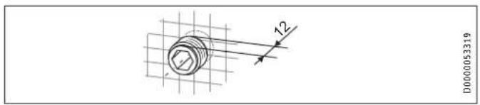
D000053319▶ Seal and insert the twin nipples.
Making the water connection
text_image
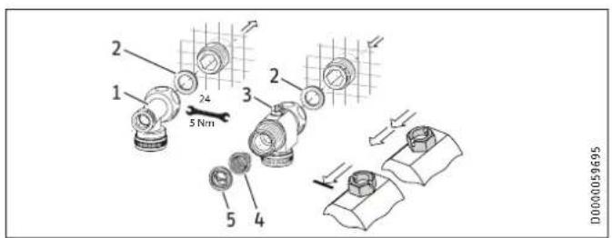
2 1 24 5 Nm 3 2 5 4 D00000596951 DHW with tee
2 Gasket
3 Cold water with 3-way ball shut-off valve
4 Strainer
5 Plastic profile washer
- Secure the tee and 3-way ball shut-off valve, each with a flag gasket, to the twin nipples.
Material losses The strainer mu
The strainer must be fitted for the appliance to function.
▶ When replacing an appliance, check whether the strainer is installed.
Installing the appliance

Note
If you are installing the appliance with flexible pipe connections, also secure the back panel with a screw.
text_image
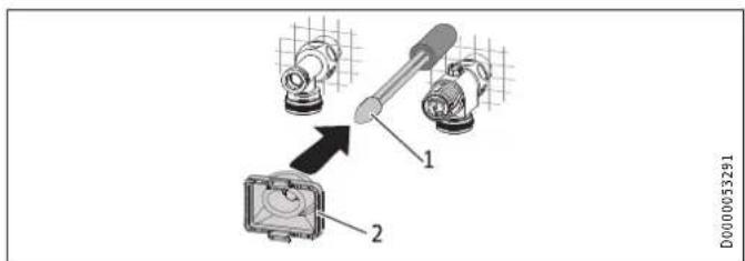
1 2 D00000532911 Cable entry installation aid
2 Cable grommet
Use the installation aid for easier wiring access through the cable grommet (see plastic parts set supplied).
▶ Remove the cable grommet from the back panel.
INSTALLATION
Installation
▶ Pull the cable grommet over the cable sheath of the power cable. For large cable cross-sections, enlarge the hole in the cable grommet if necessary.
text_image
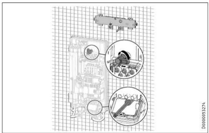
Technical diagram showing mechanical assembly with labeled components and magnified views of a device▶ Remove the transport protection plugs from the appliance pipe connections.
▶ Bend the power cable 45^ upwards.
▶ Route the power cable and cable grommet through the back panel from the rear.
▶ Install the appliance on the threaded studs of the wall mounting bracket.
▶ Press the back panel firmly into place, aligning it correctly.
- Lock the fixing toggle by turning it 90° clockwise.
▶ Pull the cable grommets into the back panel until both locking tabs engage.
text_image
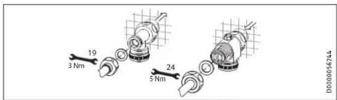
19 3 Nm 24 5 Nm D0000056244ENGLISH
▶ Fit the pipe connections with flat gaskets onto the water connections.
▶ Open the 3-way ball shut-off valve or the shut-off valve in the cold water inlet line.
INSTALLATION
Installation
Making the electrical connection

WARNING Electrocution
Carry out all electrical connection and installation work in accordance with relevant regulations.

WARNING Electrocution
The connection to the power supply must be in the form of a permanent connection in conjunction with the removable cable grommet. Ensure the appliance can be separated from the power supply by an isolator that disconnects all poles with at least 3 mm contact separation.

WARNING Electrocution
Ensure that the appliance is earthed.

Material losses
Observe the type plate. The specified rated voltage must match the power supply.
▶ Connect the power cable to the mains terminal.
Fitting the lower back panel section
natural_image
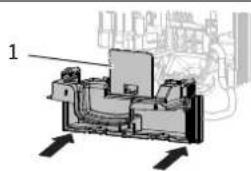
Mechanical assembly diagram showing internal components and directional arrows (no text or labels)D0000053275
1 Diffuser on lower back panel
▶ Fit the lower back panel section into the back panel. Check that both locking tabs are engaged.
▶ Align the mounted appliance by undoing the fixing toggle, aligning the power supply and back panel, and then re-tightening the fixing toggle. If the back panel does not sit flush against the wall, you can secure the appliance at the bottom with an additional screw.
Material losses
The cover plate of the lower back panel section must not bend when installed.
INSTALLATION
Commissioning
11. Commissioning
11.1 Preparation
Internal anti-scalding protection via jumper slot
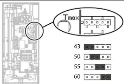
text_image
T max 43 50 55 60D0000089184
▶ Install the anti-scalding protection setting jumper in the required position (= temperature in °C) on the pin strip.
Jumper position Description
43 For example in nurseries, hospitals, etc.
50
55 Max. for shower operation
60 Factory setting
No jumper Limited to 43 °C

CAUTION Burns
If operating with preheated water, e.g. if using a solar thermal system, the internal anti-scalding protection and the temperature limit Tmax, which can be set by the user, may be exceeded.
In this case, limit the temperature with an upstream central thermostatic valve (e.g. ZTA 3/4).
INSTALLATION
Commissioning
Changing the connected load via jumper slot; only with DHE 18/21/24
If you select a connected load other than the 21 kW factory setting for appliances with selectable connected load, you will need to reposition the jumper.
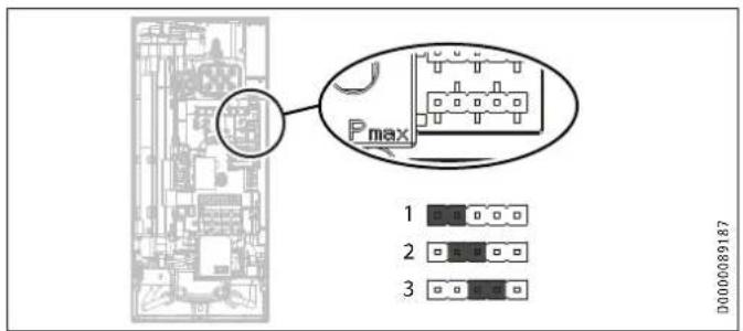
text_image
Pmax 1 2 3 D000089187▶ Install the jumper in the required position on the pin strip.
Jumper position Connected Load
| 1 18 kW | |
| 2 21 kW | |
| 3 24 kW | |
| No jumper 18 kW |
11.2 Initial start-up
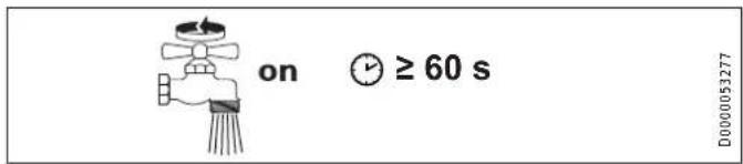
text_image
on ≥ 60 s D000053277▶ Open and close all connected draw-off valves several times, until all air has been purged from the pipework and the appliance.
Carry out a tightness check.
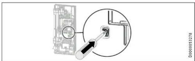
text_image
D0000053278▶ Activate the safety switch by firmly pressing the reset button (the appliance is delivered with the safety switch disabled).
INSTALLATION
Commissioning
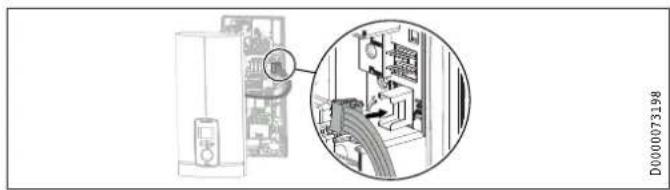
natural_image
Diagram showing a server rack connected to a device with an inset close-up of its internal components (no text or symbols visible)Connect the programming unit connecting cable to the PCB.
Tick the selected connected load and rated voltage on the appliance cover type plate (on both sides). Use a ballpoint pen to do this.
▶ Secure the appliance cover with the screw.
▶ Fit the fascia to the appliance cover.
▶ Remove the protective film from the user interface.

Note
For undersink installation, the appliance cover should be turned the other way up for easier operation; see chapter "Installation alternatives / Rotated appliance cover".
on
D0000053281
ENGLISH
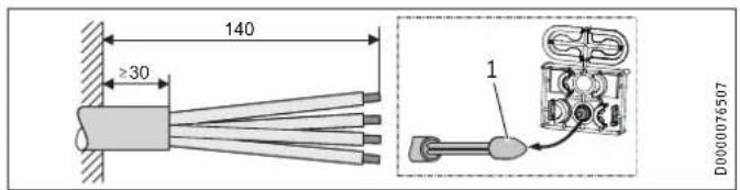
text_image
D0000053280▶ Hook the appliance cover at the top rear into the back panel.
Pivot the appliance cover downwards. Check that the appliance cover is securely seated both top and bottom.
▶ Switch on the power supply.
11.2.1 Appliance handover
Explain the appliance function to users and familiarise them with how it works.
▶ Make the user aware of potential dangers, especially the risk of scalding.
▶ Hand over the instructions.
INSTALLATION
Appliance shutdown
11.3 Recommissioning

Material losses
To ensure that the bare wire heating system is not damaged following an interruption to the water supply, the appliance must be recommissioned by taking the following steps.
▶ Disconnect the appliance from the power supply by removing the fuses/tripping the MCBs.
▶ Open the tap for at least one minute until the appliance and its upstream cold water inlet line are free of air.
▶ Switch on the power supply again.
12. Appliance shutdown
▶ Isolate all poles of the appliance from the power supply.
- Drain the appliance (see chapter "Maintenance / Draining the appliance").
13. Installation alternatives
Overview of installation alternatives
| Electrical connection IP rating | |
| On unfinished walls, connected from above IP 25 | |
| On unfinished walls, connected from below, short power cable | IP 25 |
| Finished walls IP 24 |
Water connection IP rating
| Finished walls IP 24 | |
| Other IP rating | |
| Installation with offset tiles | IP 25 |
| Rotated appliance cover | IP 25 |
| Horizontal installation of the appliance | IP 24 |

WARNING Electrocution
Before any work on the appliance, disconnect all poles from the power supply.
INSTALLATION
Installation alternatives
13.1 Electrical connection from above on unfinished walls
text_image
140 ≥30 1 D0000765071 Cable entry installation aid
▶ Prepare the power cable.
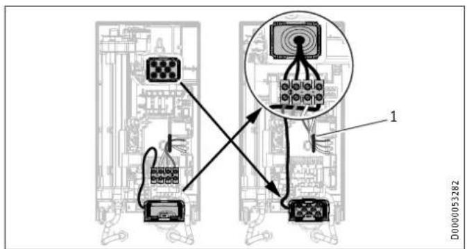
text_image
Diagram showing connections between electronic equipment blocks and a central device, with labeled components and wiring paths.1 Cable routing
▶ Reposition the mains terminal from the bottom to the top. To do this, undo the fixing screw. Turn the mains terminal with connecting cables 180^ clockwise. Route the cable around the cable guide when doing so. Secure the mains terminal in place.
▶ Replace the cable grommets.
▶ Install the cable grommet from the top at the bottom.
▶ Pull the cable grommet over the cable sheath of the pow cable.
▶ Install the appliance on the threaded studs of the wall mounting bracket.
▶ Push the back panel firmly against the wall. Lock the fixing toggle by turning it 90° clockwise.
▶ Pull the cable grommets into the back panel until both locking tabs engage.
▶ Connect the power cable to the mains terminal.

WARNING Electrocution
The connecting wires must not protrude beyond the level of the mains terminal.
INSTALLATION
Installation alternatives
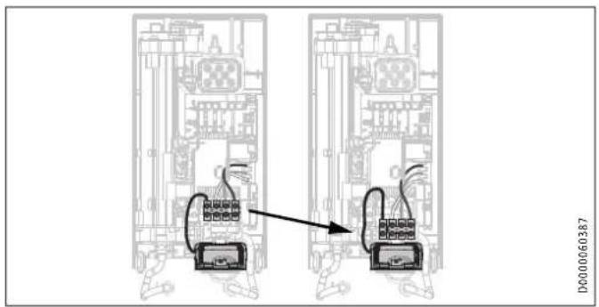
13.2 Electrical connection on unfinished walls from below with short power cable
text_image
D000060387▶ Reposition the mains terminal further downwards. To do this undo the fixing screw. Secure the mains terminal in place.
13.3 Electrical connection on finished walls

Note
This type of connection changes the IP rating of the appliance.
▶ Change the type plate. Cross out "IP 25" and mark the box "IP 24". Use a ballpoint pen to do this.
text_image
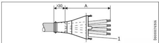
30 A 1 D00000765061 Cable grommet
Electrical connection on finished walls Dimension A
Positioned in lower section of appliance 160
Positioned in upper section of appliance 110
▶ Prepare the power cable. Fit the cable grommet.

Material losses
If you break out the wrong knock-out in the back panel/appliance cover by mistake, you must use a new back panel/appliance cover.
▶ Cleanly cut and break out the required cable entries from the back panel and appliance cover (for the positions, see chapter "Specification / Dimensions and connections"). Deburr any sharp edges with a file.
Route the power cable through the cable grommet.
▶ Connect the power cable to the mains terminal.
INSTALLATION
Installation alternatives
13.4 Connecting a load shedding relay
Install a load shedding relay in the distribution board in conjunction with other electric appliances, e.g. electric storage heaters. The relay responds when the instantaneous water heater starts.

Material losses
Connect the phase that switches the load shedding relay to the indicated terminal of the mains terminal in the appliance (see chapter "Specification / Wiring diagram").
13.5 Water installation on finished walls

Note
This type of connection changes the IP rating of the appliance.
▶ Change the type plate. Cross out "IP 25" and mark the box "IP 24". Use a ballpoint pen to do this.
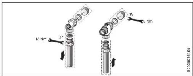
text_image
18 Nm 24 19 5 Nm D0000033104▶ Fit water plugs with gaskets to seal the concealed connections. All taps obtained as accessories are supplied with plugs and gaskets in the standard delivery. For pressure taps other than those recommended by us, plugs and gaskets can be ordered as accessories.
▶ Fit a suitable pressure tap.
▶ Push the lower back panel section under the connection pipes of the tap and push it into the back panel.
- Secure the connection pipes to the tee and the 3-way ball shut-off valve.

Note
You can break off the pipe fitting tabs on the lower back panel section if required.
INSTALLATION
Installation alternatives
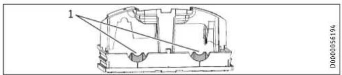
text_image
1 D00000561941 Tab
13.6 Water installation on finished walls with solder/press fittings

Note
This type of connection changes the IP rating of the appliance.
▶ Change the type plate. Cross out "IP 25" and mark the box "IP 24". Use a ballpoint pen to do this.
You can connect copper or plastic pipes with the accessories "solder fitting" or "press fitting".
With "solder fitting" with threaded fitting for 12 mm copper pipes, proceed as follows:
▶ Push the union nuts over the connection pipes.
▶ Solder the inserts to the copper pipes.
▶ Push the lower back panel section under the connection pipes of the tap and push it into the back panel.
- Secure the connection pipes to the tee and the 3-way ball shut-off valve.

Note
Observe the tap manufacturer's instructions.
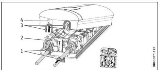
13.7 Fitting appliance cover for water installation on finished walls
text_image
1 2 3 4 D0000731701 Back panel guides
2 Screw
3 Cover guides with sealing lips on the pipe side
4 Pipe knock-out
▶ Cleanly saw and break out the pipe knock-outs in the appliance cover. If necessary, use a file.
▶ Click the cover guides into place in the knock-outs.
INSTALLATION
Installation alternatives
Only if using the "solder fitting" accessory and with precise adherence to all installation dimensions:
▶ Break the sealing lips out of the cover guides.
▶ Position the back panel guides on the pipes. Push them together. Then push the guides against the back panel as far they will go.
▶ Secure the lower back panel section with a screw.

Note
You can use the cover guides with sealing lips to compensate for a slight offset of the connection pipes and/or if using the "press fitting" accessory. In this case, the back panel guides are not fitted.
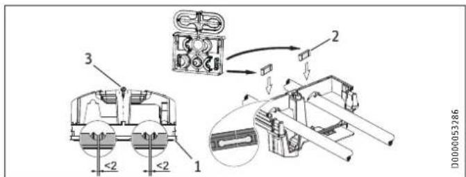
13.8 Lower back panel section installation with threaded fittings on finished walls
text_image
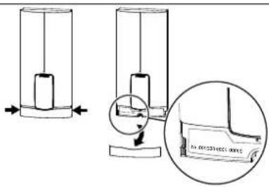
<2 1 2 3 D00000532861 Lower back panel section
2 Connection piece in the standard delivery
3 Screw
If using threaded fittings on finished walls, the lower back panel section can also be installed after fitting the taps. To do this, carry out the following steps:
▶ Cut open the lower back panel section.
▶ Fit the lower back panel section by bending it out at the sides and guiding it over the pipes.
▶ Insert the connection pieces into the lower back panel section from behind.
▶ Click the lower back panel section into place.
▶ Secure the lower back panel section with a screw.
INSTALLATION
Installation alternatives
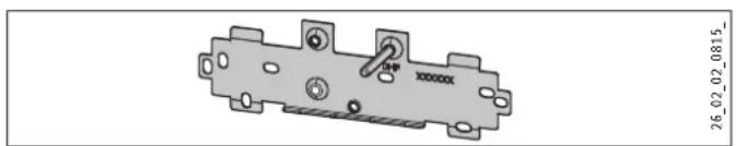
13.9 Wall mounting bracket when replacing an appliance
An existing STIEBEL ELTRON wall mounting bracket may be used when replacing appliances (except the DHF instantaneous water heater), as long as the fixing screw is in the lower right position.
Replacing a DHF instantaneous water heater
natural_image
Mechanical component diagram with mounting holes and a central shaft (no text or symbols)▶ Reposition the fixing screw on the wall mounting bracket (the Maximum tile offset
fixing screw has a self-tapping thread).
▶ Rotate the wall mounting bracket 180^ and mount it on the wall (the DHF logo is then turned towards you).
13.10 Installation with offset tiles
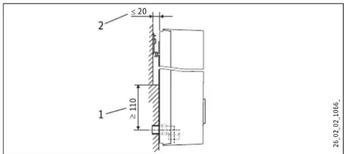
text_image
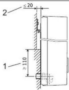
2 ≤ 20 1 ≥ 110 26_02_02_1066_1 Minimum contact area of the appliance
Maximum tile offset
▶ Adjust the wall clearance. Lock the back panel in place using the fixing toggle (turn 90° clockwise).
INSTALLATION
Installation alternatives
13.11 Rotated appliance cover
The appliance cover should be turned the other way up for undersink installation.
text_image
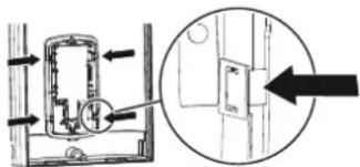
Diagram showing a door lock mechanism with directional arrows and a magnified inset view of the lock structure.
natural_image
Diagram showing two connected devices with a cable, no text or symbols presentD0000073012
▶ Remove the programming unit from the appliance cover by pressing the locking hooks and removing the programming unit.
▶ Turn the appliance cover (not the appliance) the other way up and refit the programming unit. Push the programming unit home in parallel until all locking tabs engage. When engaging the locking tabs, apply counter pressure by pushing against the appliance cover from the inside.

WARNING Electrocution
All 4 locking tabs on the programming unit must click into place. The locking tabs must be complete and undamaged. If the programming unit is not inserted correctly, user protection against contact with live components cannot be ensured.
▶ Insert the connecting cable plug of the programming unit into the PCB (see chapter "Commissioning / Initial start-up").
▶ Hook the appliance cover in at the bottom. Pivot the appliance cover up to the back panel.
▶ Secure the appliance cover.
▶ Fit the cover onto the appliance cover.
13.12 Operation with preheated water
You can limit the maximum inlet temperature by installing a central thermostatic valve.
INSTALLATION
Installation alternatives
13.13 Horizontal installation of the appliance

Note
For the horizontal installation alternative, please note the following points:
- Installation is only permissible with direct wall mounting. The universal mounting frame cannot be used.
- The installation versions "Installation with offset tiles" and "Rotated appliance cover" are not permissible.
- This type of connection changes the IP rating of the appliance. Cross out "IP 25" on the type plate and mark the box "IP 24". Use a ballpoint pen to do this.
Horizontal installation
The appliance can also be mounted horizontally on the wall (turned 90° to the left, with the water connections on the right). The installation, water and electrical connections are described in chapters "Standard installation" and "Installation alternatives".
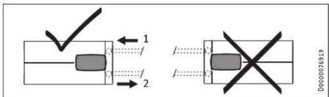
text_image
1 2 D000076919The appliance cover must be provided with a condensate drain opening of min. ∅ 5.0 mm to max. ∅ 6.0 mm at the marked position.
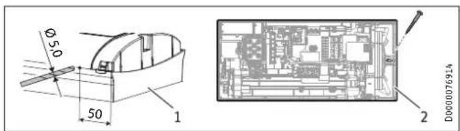
text_image
Ø50 50 1 2 D0000769141 Appliance cover with opening for condensate drain
2 Back panel with additional fixing screw
INSTALLATION
Service information
▶ Drill a hole from the outside through the dismantled appliance cover at the marked point. Alternatively, you can punch a hole in the appliance cover from the inside at the marked point. In this case, you must then enlarge the hole to the required diameter from the outside. Deburr any sharp edges with a file.
▶ Secure the appliance back panel with an additional screw.

Material losses
An appliance cover with an existing condensate drain opening must no longer be used for vertical installation of the appliance.
14. Service information
Overview of connections
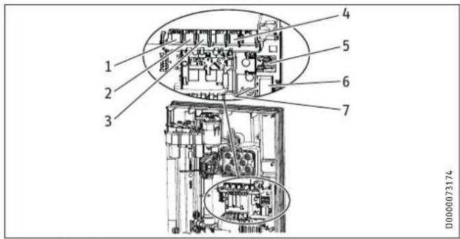
text_image
1 2 3 4 5 6 7 D0000731741 Motorised valve
2 Flow sensor
3 High limit safety cut-out, automatic reset
4 NTC sensor
5 Pin strips for connected load and anti-scalding protection
6 Programming unit plug-in position
7 Diagnostic traffic lights
INSTALLATION
Troubleshooting
Appliance cover retainer
natural_image
Architectural floor plan showing room layouts and equipment layout (no text or labels)15. Troubleshooting

WARNING Electrocution
To test the appliance, it must be connected to the power supply.

Note
When testing the appliance using the diagnostic traffic lights, water must be flowing.
Signals of the diagnostic traffic lights (LED)
| ●○○ | Red Lights up in the event of a fault | |
| ○●○ | Yellow | Illuminates in heating mode/flashes when output limit reached |
| ○○● | Green Flashing: Appliance connected to power supply | |
INSTALLATION
Troubleshooting
| Diagnostic traffic lights (draw-off mode) | Fault | Cause | Remedy |
| No LED illuminates Appliance does not heat upPCB faulty Replace the function module | One or more power supply phases are missing Check the fuses in the distribution board | ||
| Green flashing, yellow off, red off | No DHW | Appliance starting flow rate not reached; shower head/aerator scaled up | Descale/replace the shower head/aerator |
| Appliance starting flow rate not reached; strainer in cold water inlet dirty | Clean strainer | ||
| Flow meter not plugged in Check plug-in connection; correct if necessary | |||
| Flow meter faulty or dirty Replace flow meter | |||
| PCB faulty Replace the function module | |||
| Green flashing, yellow on, red off | No display | Loose connecting cable between PCB and programming unit | Check plug-in connections; correct if necessary |
| Faulty connecting cable between PCB and programming unit | Check connecting cable; replace if necessary | ||
| Programming unit faulty | Replace programming unit | ||
| PCB faulty Replace the function module | |||
| Green flashing, yellow on, red off | No DHW; outlet temperature does not match set value | Tap faulty | Replace tap |
| Outlet sensor faulty | Replace outlet sensor | ||
| Heating system faulty | Replace the function module | ||
| PCB faulty Replace the function module | |||
| Green flashes, yellow flashes, red off | No DHW; outlet temperature does not match set value | Motorised valve faulty | Replace motorised valve |
| Green flashing, yellow off, red on | No DHW | One or more power supply phases are missing Check the fuses in the distribution board | |
| Air detection has responded | Continue draw-off for >1 min | ||
INSTALLATION
Troubleshooting
15.1 Fault code display
If there is an appliance fault, the spanner flashes on the display.
▶ To call up the fault code display, press the "i" button for more
than 5 seconds.
| Diagnostic traffic lights (draw-off mode) | Display shown | Fault | Cause | Remedy |
| Green flashing, yellow off, red on | Spanner flashes (fault code display E1 and spanner) | No DHW | Safety switch not activated during "Commissioning" | Activate the safety switch by firmly pressing the reset button |
| Safety switch was triggered by high limit safety cut-out | Check high limit safety cut-out (plug-in connection, connecting cable); activate safety switch | |||
| Safety switch responds again after high limit safety cut-out has been checked; high limit safety cut-out faulty | Replace high limit safety cut-out; activate safety switch and draw-off with maximum set value >1 min | |||
| Safety switch responds again; PCB | faulty | Replace the function module | ||
| Green flashing, yellow off, red on | Spanner flashes (fault code display E2 and spanner) | No DHW PCB faulty (lead break or short circuit in inlet sensor) | Replace the function module | |
| Green flashing, yellow off, red on | Spanner flashes (fault code display E3 and spanner) | No DHW Short circuit in outlet sensor | Check outlet sensor; | replace if necessary |
INSTALLATION
Maintenance
16. Maintenance

WARNING Electrocution
Before any work on the appliance, disconnect all poles from the power supply.
This appliance contains capacitors which are discharged when disconnected from the power supply. The capacitor discharge voltage may briefly exceed 60 V DC.
Draining the appliance
The appliance can be drained for maintenance work.

WARNING Burns
Hot water may escape when you drain the appliance.
▶ Close the 3-way ball shut-off valve or the shut-off valve in the cold water inlet line.
▶ Open all draw-off valves.
▶ Undo the pipe connections from the appliance.
▶ Store the dismantled appliance free from the risk of frost, as water residues remaining inside the appliance can freeze and cause damage.
Clean strainer
If the strainer in the threaded cold water fitting is dirty, clean it. Close the 3-way ball shut-off valve or the shut-off valve in the cold water inlet line before removing, cleaning and refitting the strainer.
INSTALLATION
Specification
17. Specification
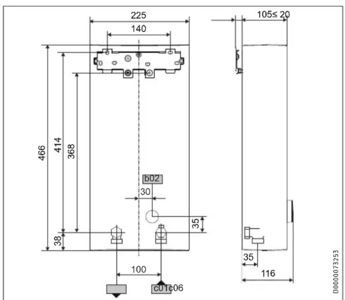
17.1 Dimensions and connections
text_image
225 140 466 414 368 b02 30 38 100 C01c06 105≤20 35 116 D0000073253| DHE | |||
| b02 | Entry for electrical cables | Unfinished walls | ||
| c01 | Cold water inlet Male thread | G 1/2 A | |
| c06 | DHW outlet | Male thread | G 1/2 A |
Alternative connection options
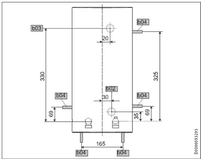
text_image
b03 330 20 b04 b02 30 b04 325 69 35 69 165 b04 b04 D0000053293| DHE | ||
| b02 | Entry for electrical cables I Unfinished walls | |
| b03 | Entry for electrical cables II Unfinished walls | |
| b04 | Entry electrical cables III Finished walls | |
INSTALLATION
Specification
17.2 Wiring diagram
3/PE \~ 380-415 V
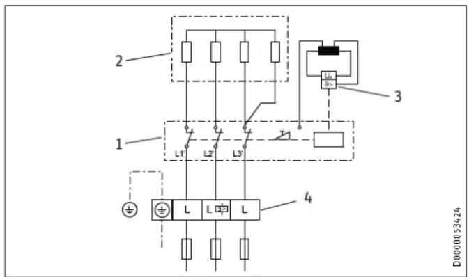
text_image
2 1 L1 L2 L3 4 3 D0000534241 Power PCB with integral safety switch
2 Bare wire heating system
3 High limit safety cut-out
4 Mains terminal
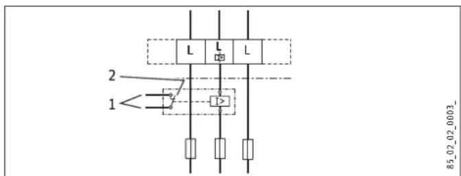
Priority control with LR 1-A
text_image
2 1 L L L 12 85_02_02_0003_1 Control cable to the contactor of the second appliance (e.g. electric storage heater)
2 Control contact drops out when switching the instantaneous water heater on.
INSTALLATION
Specification
17.3 DHW output
The DHW output is subject to the connected power supply, the appliance's connected load and the cold water inlet temperature. The rated voltage and rated output can be found on the type plate.
Connected load in kW 38 °C DHW output in L/min.
Rated voltage Cold water inlet temperature
380 V 400 V 415 V 5 °C 10 °C 15 °C 20 °C
| DHE 18/21/24 | |||||
| 16.2 | 7.0 | 8.3 | 10.1 | 12.9 | |
| 19.0 | 8.2 | 9.7 | 11.8 | 15.1 | |
| 21.7 | 9.4 | 11.1 | 13.5 | 17.2 | |
| 18.0 | 7.8 | 9.2 | 11.2 | 14.3 | |
| 21.0 | 9.1 | 10.7 | 13.0 | 16.7 | |
| 24.0 | 10.4 | 12.2 | 14.9 | 19.0 | |
| 19.4 | 8.4 | 9.9 | 12.0 | ||
| 22.6 | 9.8 | 11.5 | 14.0 | ||
| 25.8 | 11.2 | 13.2 | 16.0 | ||
| DHE 27 | |||||
| 24.4 | 10.6 | 12.4 | 15.2 | 19.4 | |
| 27.0 | 11.7 | 13.8 | 16.8 | 21.4 | |
Connected load in kW 50 °C DHW output in L/min.
Rated voltage Cold water inlet temperature
380 V 400 V 415 V 5 °C 10 °C 15 °C 20 °C
| DHE 18/21/24 | |||||
| 16.2 | 5.1 | 5.8 | 6.6 | 7.7 | |
| 19.0 | 6.0 | 6.8 | 7.8 | 9.0 | |
| 21.7 | 6.9 | 7.8 | 8.9 | 10.3 | |
| 18.0 | 5.7 | 6.4 | 7.3 | 8.6 | |
| 21.0 | 6.7 | 7.5 | 8.6 | 10.0 | |
| 24.0 | 7.6 | 8.6 | 9.8 | 11.4 | |
| 19.4 | 6.2 | 6.9 | 7.9 | ||
| 22.6 | 7.2 | 8.1 | 9.2 | ||
| 25.8 | 8.2 | 9.2 | 10.5 | ||
| DHE 27 | |||||
| 24.4 | 7.7 | 8.7 | 10.0 | 11.6 | |
| 27.0 | 8.6 | 9.6 | 11.0 | 12.9 | |
17.4 Application areas / conversion table
Electrical resistivity and electrical conductivity
| Standard specification at 15 °C | 20 °C | 25 °C | ||||||
| Resistivity ≥ | Conductivity ≤ | Resistivity ≥ | Conductivity ≤ | Resistivity ≥ | Conductivity ≤ | |||
| mS/m | μS/cm | mS/m | μS/cm | mS/m | μS/cm | |||
| 900 | 111 | 1111 | 800 | 125 | 1250 | 735 | 136 | 1361 |
INSTALLATION
Specification
17.5 Pressure drop
Fittings
| Tap pressure drop at a flow rate of 10 L/min | |
| Mono lever mixer tap, approx. MPa 0.04 - 0.08 | |
| Thermostatic valve, approx. MPa 0.03 - 0.05 | |
| Shower head, approx. MPa 0.03 - 0.15 | |
Sizing the pipework
When calculating the size of the pipework, an appliance pressure drop of 0.1 MPa is recommended.
17.6 Fault conditions
In the event of a fault, loads up to 80 °C at a pressure of 1.0 MPa can occur briefly in the installation.
17.7 Energy consumption data
Product datasheet: Conventional water heaters to regulation (EU) no. 812/2013 | 814/2013
| DHE 18/21/24 DHE 27 | |||
| 202656 | 202657 | ||
| Manufacturer | STIEBEL ELTRON | STIEBEL ELTRON | |
| Load profile | S | S | |
| Energy efficiency class | A | A | |
| Energy conversion efficiency | % | 39 | 39 |
| Annual power consumption | kWh | 476 | 475 |
| Default temperature setting | °C | 60 | 60 |
| Sound power level | dB(A) | 15 | 15 |
| Special information on measuring efficiency | Measured at ECO level with highest flow rate, maximum output and maximum set value. | Measured at ECO level with highest flow rate and maximum set value | |
| Daily power consumption | kWh | 2,184 | 2,177 |
INSTALLATION
Specification
17.8 Data table
| DHE 18/21/24 DHE 27 | ||||||
| 202656 202657 | ||||||
| Electrical data | ||||||
| Rated voltage | V | 380 | 400 | 415 | 380 | 400 |
| Rated output | kW | 16.2/19/21.7 | 18/21/24 | 19.4/22.6/25.8 | 24.4 | 27 |
| Rated current | A | 27.6/29.5/33.3 | 29/31/35 | 30.1/32.2/36.3 | 37.1 | 39 |
| Fuse protection | A | 32/32/35 | 32/32/35 | 32/32/40 | 40 | 40 |
| Frequency | Hz | 50/60 | 50/60 | 50/- | 50/- | 50/- |
| Phases | 3/PE | 3/PE | ||||
| Resistivity ρ15 ≥ | Ω cm | 900 | 900 | |||
| Conductivity σ15 ≤ | μS/cm | 1111 | 1111 | |||
| Max. mains impedance at 50 Hz | Ω | 0.248 | 0.236 | 0.227 | 0.221 | 0.210 |
| Connections | ||||||
| Water connection | G 1/2 A | G 1/2 A | ||||
| Application limits | ||||||
| Max. permissible pressure | MPa | 1 | 1 | |||
| Max. inlet temperature for reheating | °C | 55 | 55 | |||
| Values | ||||||
| Max. inlet temperature (e.g. pasteurisation) | °C | 70 | 70 | |||
| On | l/min | >2.5 | >2.5 | |||
| Flow rate at 28 K | l/min | 9.2/10.7/12.3 at 400 V | 13.8 at 400 V | |||
| Flow rate at 50 K | l/min | 5.2/6.0/6.9 at 400 V | 7.7 at 400 V | |||
| Pressure drop for flow rate at 50 K (without flow limiter) | MPa | 0.06/0.08/0.1 | 0.13 | |||
| Hydraulic data | ||||||
| Nominal capacity | l | 0.4 | 0.4 | |||
INSTALLATION
Specification
| DHE 18/21/24 DHE 27 | |||
| Versions | |||
| Adjustable connected load X - | |||
| Temperature settings °C Off, 20-60 Off, 20-60 | |||
| Protection class | 1 | 1 | |
| Insulating block | Plastic | Plastic | |
| Heating system heat generator | Bare wire | Bare wire | |
| Cover and back panel | Plastic | Plastic | |
| Colour | White | White | |
| IP rating | IP 25 | IP 25 | |
| Dimensions | |||
| Height | mm | 466 | 466 |
| Width | mm | 225 | 225 |
| Depth | mm | 116 | 116 |
| Weights | |||
| Weight | kg | 3.1 | 3.1 |

Note
The appliance conforms to IEC 61000-3-12.
GUARANTEE | ENVIRONMENT AND RECYCLING
Guarantee
The guarantee conditions of our German companies do not apply to appliances acquired outside of Germany. In countries where our subsidiaries sell our products a guarantee can only be issued by those subsidiaries. Such guarantee is only granted if the subsidiary has issued its own terms of guarantee. No other guarantee will be granted.
We shall not provide any guarantee for appliances acquired in countries where we have no subsidiary to sell our products. This will not affect warranties issued by any importers.
Environment and recycling
We would ask you to help protect the environment. After use, dispose of the various materials in accordance with national regulations.
TABLE DES MATIÈRES
REMARQUES PARTICULIÈRES
UTILISATION
text_image
Diagram illustrating a mechanical assembly or lifting process with labeled components and an inset detail view showing a component with dimension annotation.D0000053312
INSTALLATION
Sécurité
INSTALLATION
7. Sécurité
9.3 Installation hydraulique
natural_image
Three sequential diagrams showing a cylindrical object being inserted into a base, with arrows indicating the process (no text or symbols present)D0000053271
INSTALLATION
Montage
natural_image
Mechanical assembly diagram showing two views of a device with internal components and directional arrows (no text or symbols)natural_image
Technical diagram of a mechanical component with mounting holes and directional arrows on a grid background (no text or symbols)text_image
Technical diagram of a mechanical assembly with labeled components and magnified views showing internal parts.natural_image
Mechanical assembly diagram showing a component with directional arrows, no visible text or symbolsD0000053275
natural_image
Technical diagram showing a refrigerator unit and its close-up of internal components (no text or symbols visible)natural_image
Three-step diagram showing a cylindrical device being inserted into a base, with an arrow indicating the process (no text or symbols present)text_image
Diagram showing connections between electronic equipment blocks with labeled components and a magnified inset highlighting a central device.1 Câblage
natural_image
Mechanical component diagram with mounting holes and a central shaft (no text or symbols)text_image
Diagram showing a door lock mechanism with directional arrows and a magnified inset view of the lock structure.
natural_image
Diagram showing two connected devices with a cable, no text or symbols presentD0000073012

natural_image
Architectural floor plan showing room layout and equipment placement (no text or labels)text_image
2 1 L1' L2' L3' 4 3 L1 L D0000053424text_image
2 1 L L L I2 85_02_02_0003_text_image
375°C 125- 4 3 5 6 7 ① i ② 2 + 1 Made in JanuaryD0000091079
text_image
Diagram illustrating a mechanical or fluid system with labeled components and directional arrows, including an inset magnified view.D0000053312
INSTALLATIE
Veiligheid
INSTALLATIE
7. Veiligheid
text_image
Diagram showing three stages of a mechanical device with labeled parts and directional arrows indicating motion or assembly.INSTALLATIE
Montage
natural_image
Mechanical assembly diagram showing two views of a device with internal components and directional arrows (no text or symbols)natural_image
Technical diagram of a mechanical component with mounting holes and mounting points, displayed on grid background (no text or symbols)▶ Monteer de wandbevestiging.
text_image
Technical diagram showing mechanical assembly with labeled components and magnified views of partsnatural_image
Mechanical assembly diagram showing internal components and directional arrows (no text or labels)D0000053275
natural_image
Diagram showing a refrigerator with a magnified inset of a kitchen appliance (no text or symbols present)▶ Steek de verbindingskabel van de bedieningseenheid op de elektronica.

Info
natural_image
Three-step diagram showing a device with a cylindrical component being inserted into a container, then moving to a base (no text or symbols present)natural_image
Mechanical component diagram with mounting holes and a central pin (no text or symbols)text_image
Diagram showing a door lock mechanism with directional arrows and a magnified inset view of the lock structure.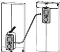
natural_image
Diagram showing two connected devices with a cable, no text or symbols presentD0000073012
natural_image
Architectural floor plan showing room layout and furniture placement (no text or labels)15. Storingen verhelpen

WAARSCHUWING verbranding
text_image
Diagram illustrating a mechanical assembly process with labeled parts and an inset magnified view showing a component detail.DOOOO5312
natural_image
Three sequential diagrams showing a cylindrical device with a base, with arrows indicating motion and a small object nearby (no text or symbols)natural_image
Mechanical assembly diagrams showing two views of a valve mechanism (no text or labels)natural_image
Technical diagram of a mechanical component with mounting holes and internal features, displayed on grid paper (no text or symbols)text_image
Technical diagram showing a mechanical assembly with three circular insets highlighting different components, including a gear and tool.natural_image
Technical diagram of a mechanical assembly with directional arrows, no visible text or symbolsD0000053275
natural_image
Diagram showing a magnified view of a mechanical component inserted into a bracket, with no visible text or symbols.D0000053278
natural_image
Diagram showing a refrigerator with a close-up view of its interior components (no text or symbols present)D0000073198
natural_image
Three sequential diagrams showing a mechanical device with a cylindrical component, connected to a base with an arrow indicating motion (no text or symbols)082500000
INSTALACE
Uvedení mimo provoz
natural_image
Diagram showing two identical electrical or mechanical components with wiring and connectors, no text or symbols present.D0000060387
natural_image
Mechanical component with mounting holes and a central switch (no text or symbols visible)text_image
Technical diagram showing electrical connection setup with labeled components and a magnified inset view of a device panel.natural_image
Architectural floor plan showing room layout and furniture placement (no text or labels)text_image
Diagram illustrating a mechanical or electrical setup with labeled components and directional arrows, including a magnified inset showing a component detail.D0000053312
INSTALACJA
Bezpieczeństwo
INSTALACJA
7. Bezpieczeństwo
text_image
Diagram showing three stages of a device with labeled parts and directional arrows indicating motion or assembly.natural_image
Mechanical assembly diagrams showing two views of a mechanical component with no visible text or symbolsnatural_image
Technical diagram of a mechanical component with mounting holes and internal features, displayed on grid paper (no text or symbols)text_image
Technical diagram showing a mechanical assembly with three circular insets highlighting different components, including a worker in a workshop.natural_image
Diagram showing a refrigerator with a close-up of its interior air conditioner unit (no text or symbols visible)D0000073198
natural_image
Three sequential diagrams showing a mechanical setup with a cylindrical component, a spring, and a base with an arrow indicating motion (no text or symbols)D0000053280
natural_image
Technical cross-section diagram of a mechanical component with labeled part 1 (no readable text or symbols beyond label)1 łącznik
text_image
Technical diagram of a mechanical assembly with labeled components and dimensional annotationsnatural_image
Mechanical component diagram with mounting holes and a central pin (no text or symbols)text_image
Diagram showing a door lock mechanism with directional arrows and a magnified inset view of the lock structure.
natural_image
Diagram showing two connected devices with a cable, no text or symbols presentD0000073012
natural_image
Architectural floor plan showing room layout and equipment placement (no text or labels)INSTALACJA
Usuwanie usterek
text_image
2 1 L L L 12 85_02_02_0003_natural_image
Floor plan diagram of a residential apartment with furniture layout (no text or labels)text_image
Diagram showing a door mechanism with directional arrows and a magnified inset highlighting the interior detail.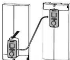
text_image
Diagram showing two connected devices with a labeled connection point, likely illustrating a measurement or control system.D0000073012
text_image
2 ≤20 1 ≥11026 02 02 1066
natural_image
Mechanical component diagram with mounting holes and a central switch (no text or symbols)natural_image
Cross-sectional diagram of a mechanical assembly with no visible text or symbolsD0000056194
1 لسان
4.33.13.14.15.16.17.18.19.20.21.22.23.24.25.26.27.28.29.30.31.32.33.34.35.36.37.38.39.40.41.42.43.44.45.46.47.48.49.50.51.52.53.54.55.56.57.58.59.60.61.62.63.64.65.66.67.68.69.70.71.72.73.74.75.76.77.78.79.80.81.82.83.84.85.86.87.88.89.90.91.92.93.94.95.96.97.98.99.100
text_image
Diagram showing two connected devices with connectors and wiring, indicating a process or system change.D0000060387
natural_image
Diagram showing a refrigerator with a magnified inset of a kitchen appliance (no text or symbols present)natural_image
Three sequential diagrams showing a device with a cylindrical component being inserted, then moving to a base (no text or symbols present)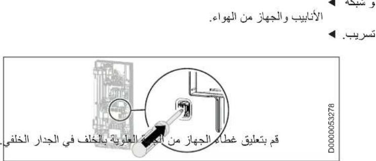
The image contains a graphical symbol (a lightning bolt inside a triangle) and no textual content. Therefore, the correct OCR output is an empty string.
The image contains a graphical symbol (a lightning bolt) inside a triangle, which is not standard alphanumeric text. According to the instructions, non-text figures/diagrams are to be ignored. Therefore, no OCR output is generated.
The image contains a graphical symbol (a lightning bolt inside a triangle) and no textual content. Therefore, the correct OCR output is an empty string.
text_image
Diagram showing mechanical assembly with labeled parts 1 and 2, including a tool and component layout291
natural_image
Technical drawing of a mechanical component with mounting holes and mounting features, set on a grid background (no text or symbols)natural_image
Mechanical assembly diagrams showing two views of a mechanical component with no visible text or symbolsnatural_image
Three sequential diagrams showing a cylindrical object being inserted into a base, with no text or symbols present.التدفق الحجمي
الجهاز.
السحب
text_image
Diagram of a bathroom sink with labeled components and directional arrows indicating flow or movement.D0000056242
294 Salmon Street | Port Melbourne
VIC 3207
Tel. 03 9645-1833 | Fax 03 9644-5091
info@stiebel-eltron.com.au
www.stiebel-eltron.com.au
Austria
STIEBEL ELTRON Ges.m.b.H.
Plant C3. XEDA International Industry City
Xiqing Economic Development Area
300085 Tianjin
Tel. 022 8396 2077 | Fax 022 8396 2075
info@stiebeleltron.cn
www.stiebeleltron.cn
Czech Republic
STIEBEL ELTRON spol. s r.o.
Urzhumskaya street 4,
building 2 | 129343 Moscow
Tel. 0495 7753889 | Fax 0495 7753887
info@stiebel-eltron.ru
www.stiebel-eltron.ru
Slovakia
STIEBEL ELTRON Slovakia, s.r.o.
Hlavná 1 | 058 01 Poprad
Tel. 052 7127-125 | Fax 052 7127-148
info@stiebel-eltron.sk
www.stiebel-eltron.sk
Switzerland
STIEBEL ELTRON AG
Industrie West
Gass 8 | 5242 Lupfig
Tel. 056 4640-500 | Fax 056 4640-501
info@stiebel-eltron.ch
www.stiebel-eltron.ch
Thailand
STIEBEL ELTRON Asia Ltd
469 Moo 2 Tambol Klong-lik
Amphur Bangpa-In | 13160 Ayutthaya
Tel. 035 220088 | Fax 035 221188
info@stiebeleltronasia.com
www.stiebeleltronasia.com
United Kingdom and Ireland
STIEBEL ELTRON UK Ltd
Unit 12 Stadium Court
Stadium Road | CH62 3RP Bromborough
Tel. 0151 346-2300 | Fax 0151 334-2913
info@stiebel-eltron.co.uk
www.stiebel-eltron.co.uk
United States of America
STIEBEL ELTRON, Inc.
17 West Street | 01088 West Hatfield MA
Tel. 0413 247-3380 | Fax 0413 247-3369
info@stiebel-eltron-usa.com
www.stiebel-eltron-usa.com
STIEBEL ELTRON
Irrtum und technische Änderungen vorbehalten! | Subject to errors and technical changes! | Sous réserve d'erreurs et de modifications techniques! | Onder voorbehoud van vergissingen en technische wijzigingen! | Salvo error o modific aciontechnica! | Excepto erro ou alteraçatécnica | Zastrzezone zmianytechniczne i ewentualne będyl | Mylya technikézmýjs ou vyhrazeny! | Amuszak iváltoztatások éstévedésej koäfte nntartjuk! | Osttvsüthie ошибokne garantiuret. Возможны технические изменения. | Chyby a techniké zmeny sú vyhradeně! Stand 9535