DEL 27 Plus - Boiler STIEBEL ELTRON - Free user manual and instructions
Find the device manual for free DEL 27 Plus STIEBEL ELTRON in PDF.
| Product type | Electronic instantaneous water heater |
| Brand | STIEBEL ELTRON |
| Model | DEL 27 Plus |
| Power supply | Three-phase 3/PE 380-415 V, 50/60 Hz, 40 A protection |
| Nominal power | 27 kW (24.4 kW at 380 V) |
| Dimensions (H x W x D) | 466 x 225 x 116 mm |
| Weight | 3.2 kg |
| Nominal capacity | 0.4 L |
| Temperature range | OFF, 20 to 60 °C |
| Maximum admissible pressure | 1 MPa (10 bar) |
| Activation flow rate | >2.5 L/min |
| Flow rate at 28 K (400 V) | 13.8 L/min |
| Flow rate at 50 K (400 V) | 7.7 L/min |
| Protection rating | IP25 (standard), IP24 (surface-mounted) |
| Protection class | I |
| Hydraulic connection | G 1/2 A male |
| Heating system | Bare wire with plastic sheath, scale-resistant |
| ECO function | 3 flow rates limiting the flow (8, 7, 6 L/min) |
| Display | Segmented display with backlight |
| Temperature memory | 2 memory keys |
| Safety | Internal anti-scald protection (adjustable 43-60 °C), Tmax limitation, air detector |
| Compliance | EU, IEC 61000-3-12 |
| Delivery contents | Mounting bracket, template, double sleeves, 3-way shut-off valve, T-connector, seals, filter, installation accessories |
| Maintenance | Cleaning with damp cloth, descaling of taps |
Frequently Asked Questions - DEL 27 Plus STIEBEL ELTRON
User questions about DEL 27 Plus STIEBEL ELTRON
0 question about this device. Answer the ones you know or ask your own.
Ask a new question about this device
Download the instructions for your Boiler in PDF format for free! Find your manual DEL 27 Plus - STIEBEL ELTRON and take your electronic device back in hand. On this page are published all the documents necessary for the use of your device. DEL 27 Plus by STIEBEL ELTRON.
USER MANUAL DEL 27 Plus STIEBEL ELTRON
natural_image
Line drawing of a portable water heater with digital display and control panel (no text or symbols)STIEBEL ELTRON
BESONDERE HINWEISE
BEDIENUNG
text_image
QR code image containing encoded data, no visible human-readable textwww.stiebel-eltron.com/registration
INSTALLATION
natural_image
Three sequential diagrams showing a cylindrical object being placed on a base, with arrows indicating motion (no text or symbols)natural_image
Mechanical assembly diagram showing two views of a vehicle chassis with directional arrows (no text or symbols)natural_image
Technical drawing of a mechanical component with mounting holes and internal features, set on a grid background (no text or symbols)text_image
Diagram showing mechanical assembly steps with labeled components 1 and 2, including a directional arrow indicating motion.D000053291
natural_image
Illustration of a vintage office interior with furniture and two circular insets showing interior views (no text or symbols)D000005327%
natural_image
Mechanical assembly diagram showing a motor or gear mechanism with directional arrows (no text or labels)D0000053275
text_image
Diagram showing a mechanical component with an arrow pointing to a pin, possibly indicating a step or insertion process.D0000053278
natural_image
Diagram showing a refrigerator interior with a close-up of its exterior wall and a hand pointing to the refrigerator (no text or symbols present)D000007319日
natural_image
Three sequential diagrams showing a mechanical or electrical component with a downward arrow indicating motion (no text or symbols)D0000053280
natural_image
Technical line drawing of a mechanical component with no visible text or symbolsD0000056194
1 Lasche
natural_image
Mechanical component with mounting holes and a central pin (no visible text or symbols)text_image
Diagram showing a device with directional arrows and an inset close-up of the internal structure, likely illustrating a mechanical or electrical component assembly.D0000073012
natural_image
Diagram showing two connected devices with a cable, no text or symbols presenttext_image
Diagram showing a checkmark and two labeled arrows pointing to a rectangular block with internal components.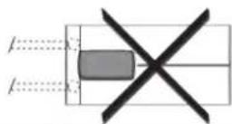
D0000076919
text_image
Architectural floor plan with labeled components and annotationsD0000076914
natural_image
Architectural floor plan showing room layouts and equipment layout (no text or labels)- General information 27
1.1 Safety instructions 27
1.2 Other symbols in this documentation 27
1.3 Units of measurement 27 - Safety 27
2.1 Intended use 27
2.2 General safety instructions 27
2.3 Test symbols 28
2.4 EU Declaration of Conformity 28 - Appliance description 28
- Settings and displays 28
4.1 User interface 28
4.2 Display symbols 29
4.3 Selecting the set temperature 29
4.4 Temperature limit via internal anti-scalding protection (qualified contractor) 29
4.5 Temperature limit Tmax (user) 29
4.6 Allocating temperature memory buttons 29
4.7 Settings menu 29
4.8 Selecting ECO level 30
4.9 Inlet temperature information 30
4.10 Recommended settings 30 - Cleaning, care and maintenance 30
- Troubleshooting 30
INSTALLATION
- Safety 31
7.1 General safety instructions 31
7.2 Shower operation 31
7.3 Instructions, standards and regulations 31 - Appliance description 31
8.1 Standard delivery 31
8.2 Accessories 31 - Preparation 32
9.1 Installation location 32
9.2 Minimum clearances 32
9.3 Water installation 32 - Installation 33
10.1 Standard installation 33 - Commissioning 35
11.1 Preparation 35
11.2 Initial start-up 35
11.3 Recommissioning 36 - Appliance shutdown 36
- Alternative installation methods 36
13.1 Electrical connection from above on unfinished walls 36
13.2 Electrical connection on unfinished walls with short power cable 37
13.3 Electrical connection on finished walls 37
13.4 Connecting a load shedding relay 37
13.5 Water installation on finished walls 37
13.6 Water installation on finished walls with solder/press-fit fittings 38
13.7 Fitting appliance cover for water installation on finished walls 38
13.8 Lower back panel section installation with threaded fittings on finished walls 38
13.9 Wall mounting bracket when replacing an appliance_38
13.10 Installation with offset tiles 38
13.11 Pivoting appliance cover 39
13.12 Horizontal installation of the appliance 39
13.13 Operation with preheated water 39
14. Service information 40
15. Troubleshooting 40
15.1 Fault code display 41
16. Maintenance 41
17. Specification 41
17.1 Dimensions and connections 41
17.2 Wiring diagram 42
17.3 DHW output 42
17.4 Application areas / Conversion table 42
17.5 Pressure drop 43
17.6 Fault conditions 43
17.7 Energy consumption data 43
17.8 Data table 43
SOFTWARE COPYRIGHT
GUARANTEE
ENVIRONMENT AND RECYCLING

Step-by-step guide
Video on installing the appli- ance

SPECIAL INFORMATION
- The appliance may be used by children aged 3 and older and persons with reduced physical, sensory or mental capabilities or a lack of experience and know-how, provided that they are supervised or they have been instructed on how to use the appliance safely and have understood the potential risks. Children must never play with the appliance. Children must never clean the appliance or perform user maintenance unless they are supervised.
- During operation, the tap can reach temperatures up to 70 °C. There is a risk of scalding at outlet temperatures in excess of 43 °C.
- The appliance is suitable for supplying a shower (shower operation). If the appliance is also or exclusively used for shower operation, the qualified contractor must adjust the temperature setting range to 55 °C or less using the internal anti-scalding protection on the appliance. When using preheated water, it must be ensured that the inlet temperature does not exceed 55 °C.
- Ensure the appliance can be separated from the power supply by an isolator that disconnects all poles with at least 3 mm contact separation.
- The specified voltage must match the power supply.
- The appliance must be connected to the earth conductor.
- The appliance must be permanently connected to fixed wiring.
- Secure the appliance as described in chapter "Installation / Installation".
-
Observe the maximum permissible pressure (see chapter "Installation / Specification / Data table").
-
The specific water resistivity of the mains water supply must not be undershot (see chapter "Installation / Specification / Data table").
- Drain the appliance as described in chapter "Installation / Maintenance / Draining the appliance".
OPERATION
1. General information
The chapters "Special information" and "Operation" are intended for both users and qualified contractors.
The chapter "Installation" is intended for qualified contractors.

Note
Read these instructions carefully before using the appliance and retain them for future reference. Pass on the instructions to a new user if required.
1.1 Safety instructions
1.1.1 Structure of safety instructions

KEYWORD Type of risk
Here, possible consequences are listed that may result from failure to observe the safety instructions.
▶ Steps to prevent the risk are listed.
1.1.2 Symbols, type of risk
| Symbol | Type of risk |
| Injury | |
| Electrocution | |
| Burns(burns, scalding) |
1.1.3 Keywords
| KEYWORD | Meaning |
| DANGER | Failure to observe this information will result in serious injury or death. |
| WARNING | Failure to observe this information may result in serious injury or death. |
| CAUTION | Failure to observe this information may result in non-serious or minor injury. |
1.2 Other symbols in this documentation

Note
General information is identified by the adjacent symbol.
▶ Read these texts carefully.
| Symbol | Meaning |
| Material losses(appliance damage, consequential losses and environmental pollution) | |
| Appliance disposal |
This symbol indicates that you have to do something. The action you need to take is described step by step.
1.3 Units of measurement

Note
All measurements are given in mm unless stated otherwise.
2. Safety
2.1 Intended use
This appliance is suitable for heating domestic hot water or for reheating preheated water. The appliance can supply one or more draw-off points.
Water will not be reheated if the maximum inlet temperature for reheating is exceeded.
The appliance is intended for domestic use. It can be used safely by untrained persons. The appliance can also be used in non-domestic environments, e.g. in small businesses, as long as it is used in the same way.
Any other use beyond that described shall be deemed inappropriate. Observation of these instructions and of the instructions for any accessories used is also part of the correct use of this appliance.
2.2 General safety instructions

CAUTION Burns
During operation, the tap can reach temperatures up to 70 °C.
There is a risk of scalding at outlet temperatures in excess of 43 °C.

CAUTION Burns
If children or persons with limited physical, sensory or mental capabilities use the appliance, set a temperature limit. Once set, check the temperature limit is working correctly.
If a permanent and unchangeable temperature limit is required, have the internal anti-scalding protection set by a qualified contractor.

CAUTION Burns
If operating with preheated water, e.g. if using a solar thermal system, observe the following information:
- The DHW temperature may exceed the set temperature or a set temperature limit.
- The dynamic anti-scalding protection between the appliance and a wireless remote control may not be effective.
▶ In such cases, limit the temperature with an upstream central thermostatic valve.

WARNING Injury
The appliance may be used by children aged 3 and older and persons with reduced physical, sensory or mental capabilities or a lack of experience and know-how, provided that they are supervised or they have been instructed on how to use the appliance safely and have understood the potential risks. Children must never play with the appliance. Children must never clean the appliance or perform user maintenance unless they are supervised.

Material losses
The user should protect the appliance and its tap against frost.
2.3 Test symbols
See type plate on the appliance.
2.4 EU Declaration of Conformity

Note
DEL Plus: STIEBEL ELTRON hereby declares that the radio equipment type complies with Directive 2014/53/EU. The full text of the EU Declaration of Conformity can be found at the following internet address: www.stiebel-eltron.de/downloads
3. Appliance description
The appliance switches on automatically as soon as you open the hot water valve on the tap. When you close the tap, the appliance switches off again automatically.
The appliance heats water as it flows through it. The set temperature is adjustable. Upwards of a certain flow rate, the control unit selects the required heating output, subject to the temperature selected and the cold water temperature.
The electronically controlled instantaneous water heater with automatic output matching maintains a consistent outlet temperature. It is irrespective of the inlet temperature, up to the maximum output of the appliance.
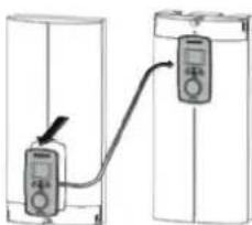
If the appliance is operated with preheated water and the inlet temperature exceeds the selected temperature, the word "hot" and the inlet temperature are displayed alternately, and the "hot" LED flashes. The water is not heated further.
You can store different set temperatures and call them up quickly. With the ECO function, the flow rate is limited to 3 preset levels. The appliance has setting options for a temperature limit (Tmax function, user) and internal anti-scalding protection (qualified contractor). The backlight switches on automatically as soon as water starts to flow through the appliance or you make a change on the user interface. The backlight switches off automatically after water stops flowing or if no action is performed.
Heating system
The bare wire heating system is enclosed within a pressure-tested plastic jacket. The heating system with its stainless steel heater spiral is suitable for hard and soft water areas and is largely in-susceptible to scale build-up. The heating system ensures rapid and efficient DHW provision.

Note
The appliance is equipped with an air detector that largely prevents damage to the heating system. If, during operation, air is drawn into the appliance, the appliance shuts down for one minute, thereby protecting the heating system.
4. Settings and displays
4.1 User interface
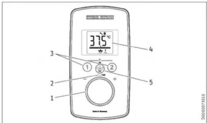
text_image
37.5°C 1 2 3 4 5 D0000792101 Temperature selector
2 "hot" scald warning LED, at temperatures higher than 43 °C
3 Temperature memory buttons 1 and 2
4 Display
5 ECO button with ECO level selection / Menu call-up
4.2 Display symbols
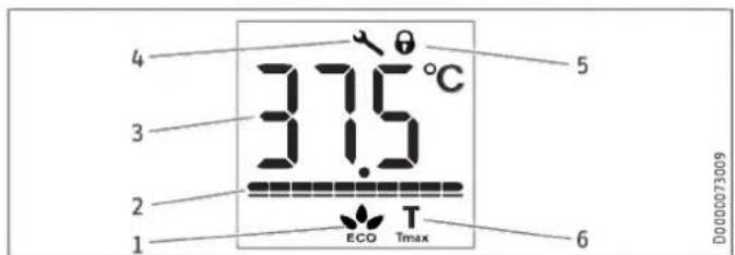
text_image
4 3 2 1 37.5°C 3 5 6 ECO Tmax D0000730091 ECO indicator [rolling, levels 1 - 3, OFF]
2 Output bar [10 - 100 %]
3 Segment display [°C/°F]
4 In the event of an appliance fault, a spanner appears
5 Operating lock [ON/OFF]
6 Tmax, displayed when temperature limit is enabled
4.3 Selecting the set temperature
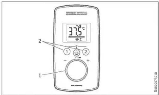
text_image
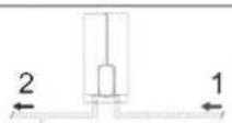
37.5°C 1 2 1 2 + - D00000730101 Set temperature settings: OFF, 20 - 60 °C
2 Call up/assign preferred temperatures
| Setting steps | |||
| Temperature range | Step | Temperature range | Step |
| 20 °C ... 35 °C | 1 °C | 68 °F ... 140 °F | 1 °F |
| 35 °C ... 43 °C | 0.5 °C | ||
| 43 °C ... 60 °C | 1 °C | ||

Note
If the outlet temperature is not high enough when the draw-off valve is fully open and the temperature selector is set to maximum, then more water is flowing through the appliance than can be heated by the heating system (appliance working at maximum output).
▶ Use the ECO button to reduce the water volume until the required temperature is achieved.
4.4 Temperature limit via internal anti-scalding protection (qualified contractor)
If required, the qualified contractor can set a permanent temperature limit, for example in nurseries, hospitals, etc.
When supplying a shower, the appliance temperature setting range must be adjusted by the qualified contractor to 55 °C or less.
If the anti-scalding protection function is enabled, "Tmax" flashes continually once the set temperature has been reached.
4.5 Temperature limit Tmax (user)
The temperature limit allows you as a user to restrict the adjustable set temperature at the appliance to a maximum value.
Your qualified contractor can set an additional temperature limit for anti-scalding protection. This temperature then dictates the upper limit of the setting range for the temperature limit function.
4.5.1 Enabling the temperature limit
▶ Press and hold buttons "1" and "2" for longer than 5 seconds, until "Tmax" and the temperature display flash.
▶ Select a temperature limit.
10 seconds after completing the setting, the menu item will disappear automatically.
If the high limit safety cut-out is enabled, "Tmax" is continuously displayed.
Check that the upper temperature limit has been correctly applied.
4.5.2 Disabling the temperature limit
▶ Disable the high limit safety cut-out by pressing and holding buttons "1" and "2" for longer than 5 seconds.
4.6 Allocating temperature memory buttons
Memory buttons "1" and "2" can each be assigned a required temperature.
▶ Select the required temperature.
▶ To store the required temperature, press and hold button "1" or "2" for longer than 3 seconds. The selected temperature flashes once to confirm.
4.7 Settings menu
| Menu | Description |
| Temperature display | Select °C or °F |
| Operating lock | Select ON or OFF. Symbol displayed |
| Fault code display | Displays E1...E3 if there is a fault on the appliance. Call qualified contractor. |
▶ To call up the menu, press and hold the ECO button for longer than 5 seconds.
▶ To select, turn the temperature selector.
▶ Press the ECO button once more.
▶ To quit the menu, press and hold the ECO button for longer than 5 seconds.
The menu switches off automatically if no operation has been performed for 30 seconds.

Note
To call up the menu when the operating lock is enabled, press and hold the ECO button for longer than 10 seconds.
4.8 Selecting ECO level
| ECO Level | Display | Flow rate limitation |
| Level 1 | 8 l/min (factory setting) | |
| Level 2 | 7 l/min | |
| Level 3 | 6 l/min | |
| OFF | No symbol | No flow rate limit |
▶ Briefly press the ECO button. Rolling selection, "Level 1 - 3/OFF".
4.9 Inlet temperature information
If the appliance is operated with preheated water and the inlet temperature exceeds the selected temperature, the word "hot" and the inlet temperature are displayed alternately, and the "hot" LED flashes.
4.10 Recommended settings
Your instantaneous water heater offers maximum precision and maximum convenience in DHW provision. Should you nonetheless be operating the appliance with a thermostatic valve, we recommend that you:
▶ Adjust the set temperature on the appliance to over 50 °C. Then set the required set temperature on the thermostatic valve.
Saving energy
The following recommended settings will result in the lowest energy consumption:
- 38 °C for hand washbasins, showers, bath
- 55 °C for kitchen sinks
Internal anti-scalding protection (qualified contractors)
If required, the qualified contractor can set a permanent temperature limit, for example in nurseries, hospitals, etc.
Limiting it in this way prevents water from flowing out of the appliance at temperatures which could cause injury.
Recommended setting for operation with a thermostatic valve and preheated water
▶ Set the temperature at the appliance to the maximum temperature.
For use in shower operation, the thermostatic valve must be set to a maximum of 55 °C.
Following an interruption to the water supply

Material losses
To ensure that the bare wire heating system is not damaged following an interruption to the water supply, the appliance must be restarted by taking the following steps.
▶ Disconnect the appliance from the power supply by removing the fuses/tripping the MCBs.
▶ Open the tap for one minute until the appliance and its upstream cold water inlet line are free of air.
▶ Switch the power back ON.
5. Cleaning, care and maintenance
▶ Never use abrasive or corrosive cleaning agents. A damp cloth is sufficient for cleaning the appliance.
▶ Check the taps regularly. Limescale deposits at the tap outlets can be removed using commercially available descaling agents.
- Troubleshooting
| Problem | Cause | Remedy |
| The appliance will not start despite the DHW valve being fully open. | There is no power. | Check the fuses/MCBs in your fuse box/distribution board. |
| The aerator in the tap or the shower head is scaled up or dirty. | Clean and/or descale the aerator or shower head. | |
| The water supply has been interrupted. | Vent the appliance and the cold water inlet line. | |
| When hot water is being drawn off, cold water flows for a short period. | The air detector detects air in the water. It switches off the heating output briefly. | The appliance restarts automatically after 1 minute. |
| The required temperature cannot be set. | The high limit safety cut-out and/or internal anti-scalding protection are enabled. | Disable temperature limiting. The internal anti-scalding protection can only be adjusted by the qualified contractor. |
| The flow rate is too low. | ECO function is enabled. | Select a different ECO level or disable the ECO function. |
| No settings can be made on the programming unit. | The operating lock is enabled. | Press and hold the ECO button for more than 10 seconds to disable the operating lock. |

Note
Programming unit displays and selected settings are retained following a power failure.
If you cannot remedy the fault, contact your qualified contractor. To facilitate and speed up your request, provide the number from the type plate (000000-0000-000000).
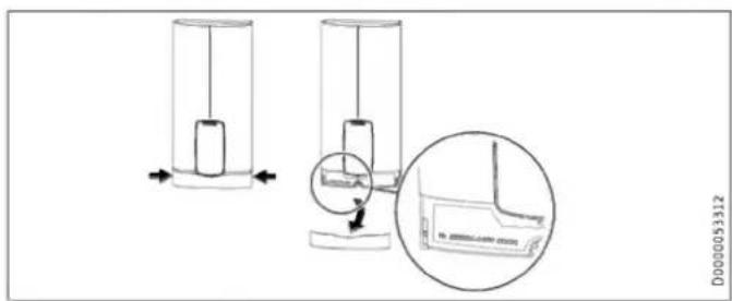
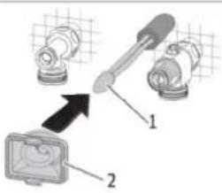
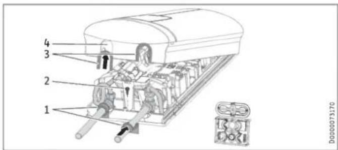
text_image
Technical diagram showing two cylindrical devices with internal components and a magnified inset highlighting a component detail.INSTALLATION

Step-by-step guide
Preparing for installation

7. Safety
Only a qualified contractor should carry out installation, commissioning, maintenance and repair of the appliance.
7.1 General safety instructions
We guarantee trouble-free function and operational reliability only if original accessories and spare parts intended for the appliance are used.

Material losses
Observe the maximum inlet temperature. Higher temperatures may damage the appliance. You can limit the maximum inlet temperature by installing a central thermostatic valve.

WARNING Electrocution
This appliance contains capacitors which are discharged when disconnected from the power supply. The capacitor discharge voltage may briefly exceed 60 V DC.
7.2 Shower operation

CAUTION Burns
- When supplying a shower, set the internal anti-scalding protection to 55 °C or less; see chapter "Commissioning / Preparations".

CAUTION Burns
If operating with preheated water, e.g. if using a solar thermal system, observe the following information:
- The DHW temperature may exceed the set temperature or a set temperature limit.
- The dynamic anti-scalding protection between the appliance and a wireless remote control may not be effective.
▶ In such cases, limit the temperature with an upstream central thermostatic valve.
7.3 Instructions, standards and regulations

Note
Observe all applicable national and regional regulations and instructions.
- The IP 24 / IP 25 protection rating can only be ensured with a correctly fitted cable grommet.
- The specific electrical resistivity of the water must not fall below that stated on the type plate. In a linked water network, factor in the lowest electrical resistivity of the water. Your water supply utility will advise you of the specific electrical water resistivity or conductivity.
8. Appliance description
8.1 Standard delivery
The following are delivered with the appliance:
- Wall mounting bracket
- Installation template
- 2 twin connectors
- 3-way ball shut-off valve for cold water
- Tee for domestic hot water
- Flat gaskets
- Strainer
- Plastic profile washer
- Plastic connection pieces/installation aid
- Cover and back panel guides
- Jumper for internal anti-scalding protection
- Jumper for output changeover (only on DEL 18/21/24 Plus)
8.2 Accessories
Wireless remote control
- FFB 4 Set EU
Taps
- MEKD mono lever kitchen pressure tap
- MEBD mono lever bath pressure tap
Plugs G 12 A
If you use taps other than the recommended pressure taps on finished walls, please use the plugs.
Installation set for finished walls
- Solder fitting - copper pipe for soldered connection ∅ 12 mm
- Press-fit fitting - copper pipe
- Press-fit fitting - plastic pipe (suitable for Viega: Sanfix-Plus or Sanfix-Fosta)
Universal mounting frame
- Mounting frame with electrical connections
Pipe assembly for undersink appliances
You will need the undersink installation set if you make the water connections (G 38 A) at the top of the appliance.
Pipe assembly for offset installation
Use this pipe assembly if you intend to offset the appliance by up to 90 mm downwards from the water connection.
Pipe assembly for replacing a gas water heater
You will need this pipe assembly set if the existing installation has gas water heater connections (cold water connection on the left-hand side, DHW connection on the right-hand side).
Pipe assembly for DHB water plug-in couplings
Use the water plug-in couplings if the existing installation contains water plug-in connections from a DHB water heater.
Load shedding relay (LR 1-A)
The load shedding relay for installation in the distribution board provides priority control for the instantaneous water heater when other appliances, such as electric storage heaters, are being operated simultaneously.
9. Preparation
9.1 Installation location

Material losses
Install the appliance in a room free from the risk of frost.
▶ Always install the appliance vertically and near the draw-off point. For horizontal installation, see chapter "Alternative installation methods / Horizontal installation of the appliance".
The appliance is suitable for undersink and oversink installation.
Undersink installation
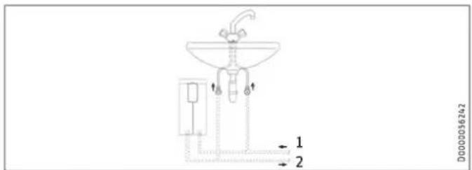
text_image
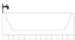
1 2 D0000056242Oversink installation
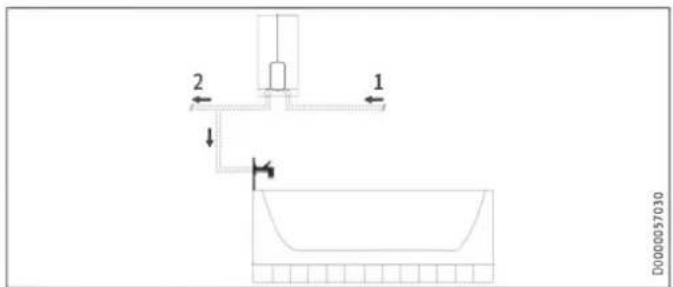
text_image
2 1 D000057030▶ Mount the appliance on the wall. The wall must have sufficient load bearing capacity.
9.2 Minimum clearances
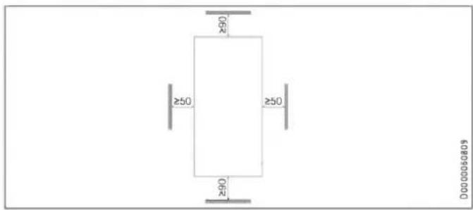
text_image
Ø92 ≥50 ≥50 Ø92 D0000060809- Maintain the minimum clearances to ensure trouble-free operation of the appliance and facilitate maintenance work.
9.3 Water installation
▶ Flush the water line thoroughly.
Taps
Use appropriate pressure taps. Open vented taps are not permissible.

Note
Never use the 3-way ball shut-off valve in the cold water inlet to reduce the flow rate. The 3-way ball shut-off valve is intended only to shut off the cold water inlet.
Permissible water line materials
- Cold water inlet line:
Pipes made from galvanised steel, stainless steel, copper or plastic
- DHW outlet line:
Pipes made from stainless steel, copper or plastic

Material losses
If plastic pipework systems are used, take into account the maximum inlet temperature and the maximum permissible pressure.
Flow rate
▶ Ensure that the flow rate for switching on the appliance is achieved.
▶ Increase the water line pressure if the required flow rate is not achieved when the draw-off valve is fully open.
10. Installation
| Factory settings | DEL 18/21/24 Plus | DEL 27 Plus | |
| Internal anti-scalding protection | °C | 60 | 60 |
| Connected load | kW | 21 | 27 |
| Adjustable connected load | x | - |
| Standard installation | DEL 18/21/24 Plus | DEL 27 Plus |
| Electrical connection from below on unfinished walls | x | x |
| Water connection on unfinished walls | x | x |
For further installation options, see chapter "Alternative installation methods".
10.1 Standard installation
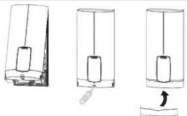
Opening the appliance
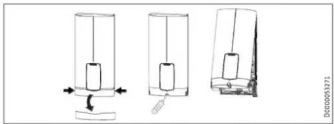
natural_image
Three sequential diagrams showing a cylindrical object being inserted into a base, with arrows indicating the process (no text or symbols present)▶ Open the appliance by holding the fascia at the side and pulling forwards away from the appliance cover. Undo the screw. Pivot open the appliance cover.

natural_image
Mechanical assembly diagrams showing two views of a device with internal components and directional arrows (no text or labels)▶ Remove the back panel by pressing the two locking tabs and pulling the lower back panel section forwards.
Preparing the power cable on unfinished walls, for connection from below
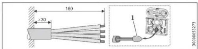
text_image
160 ≥30 1 D00000532731 Cable entry installation aid
▶ Prepare the power cable.
Fitting the wall mounting bracket
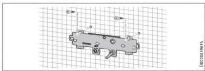
natural_image
Technical drawing of a mechanical component with mounting holes and a grid background (no text or symbols)▶ Mark out the holes for drilling using the installation template. If the appliance is to be installed on finished walls, also mark out the fixing hole in the lower section of the template.
▶ Drill the holes and secure the wall mounting bracket at 2 points using suitable fixing materials (screws and rawl plugs are not part of the standard delivery).
▶ Fit the wall mounting bracket.
Installing the twin connectors

Material losses
Carry out all water connection and installation work in accordance with regulations.
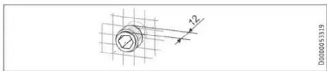
text_image
D0000053319▶ Seal and insert the twin connectors.
Making the water connection
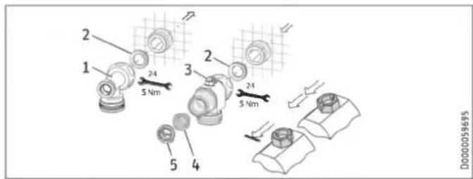
text_image
1 2 3 4 5 D00000596951 DHW with tee
2 Gasket
3 Cold water with 3-way ball shut-off valve
4 Strainer
5 Plastic profile washer
- Secure the tee and 3-way ball shut-off valve, each with a flat gasket, to the twin connector.

Material losses
The strainer must be fitted for the appliance to function.
▶ When replacing an appliance, check whether the strainer is installed.
Installing the appliance

Step-by-step guide
Installation


Note
If you are installing the appliance with flexible pipe connections, also secure the back panel with a screw.
text_image
Diagram showing mechanical assembly with labeled parts 1 and 2, including a tool and component illustrations.D0000053291
1 Cable entry installation aid
2 Cable grommet
Use the installation aid for easier wiring access through the cable grommet (see plastic parts set supplied).
▶ Remove the cable grommet from the back panel.
▶ Pull the cable grommet over the cable sheath of the power cable. For large cable cross-sections, enlarge the hole in the cable grommet if necessary.
text_image
Technical diagram showing mechanical assembly with labeled components and magnified views of a device▶ Remove the transport protection plugs from the appliance pipe connections.
▶ Bend the power cable 45^ upwards.
▶ Route the power cable and cable grommet through the back panel from the rear.
▶ Install the appliance on the threaded studs of the wall mounting bracket.
▶ Press the back panel firmly into place, aligning it correctly.
▶ Lock the fixing toggle by turning it 90° clockwise.
▶ Pull the cable grommets into the back panel until both locking tabs engage.
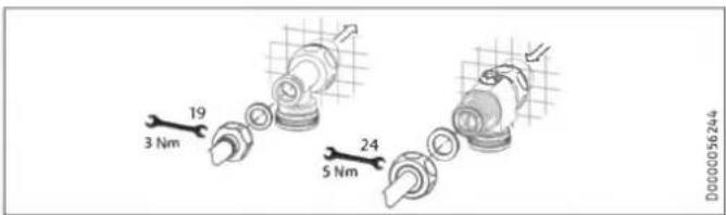
text_image
19 3 Nm 24 5 Nm D0000056244▶ Fit the pipe connections with flat gaskets onto the water connections.
▶ Open the 3-way ball shut-off valve or the shut-off valve in the cold water inlet line.
Making the electrical connection

WARNING Electrocution
Carry out all electrical connection and installation work in accordance with relevant regulations.

WARNING Electrocution
The connection to the power supply must be in the form of a permanent connection in conjunction with the removable cable grommet. Ensure the appliance can be separated from the power supply by an isolator that disconnects all poles with at least 3 mm contact separation.

WARNING Electrocution
Ensure that the appliance is earthed.

Material losses
Observe the type plate. The specified rated voltage must match the mains voltage.
▶ Connect the power cable to the mains terminal.
Fitting the lower back panel section
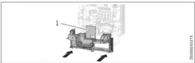
natural_image
Technical diagram of a mechanical assembly with labeled component '1' and directional arrows (no readable text or symbols)1 Diffuser on lower back panel
▶ Fit the lower back panel section into the back panel. Check that both locking tabs are engaged.
▶ Align the mounted appliance by undoing the fixing toggle, aligning the power supply and back panel, and then re-tightening the fixing toggle. If the back panel does not sit flush against the wall, you can secure the appliance at the bottom with an additional screw.

Material losses
The cover plate of the lower back panel section must not bend when installed.
11. Commissioning

Step-by-step guide
Commissioning

11.1 Preparation
Internal anti-scalding protection via jumper slot
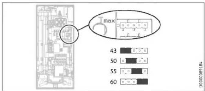
text_image
max 43 50 55 60 D000089184▶ Install the anti-scalding protection setting jumper in the required position (= temperature in °C) on the pin strip.
| Jumper position | Description |
| 43 | For example in nurseries, hospitals, etc. |
| 50 | |
| 55 | Max. for shower operation |
| 60 | Factory setting |
| No jumper | Limited to 43 °C |

CAUTION Burns
If operating with preheated water, e.g. if using a solar thermal system, the internal anti-scalding protection and the temperature limit Tmax, which can be set by the user, may be exceeded.
▶ In this case, limit the temperature with an upstream central thermostatic valve.
Changing connected load via jumper slot, DEL 18/21/24 Plus only
If you select a connected load other than the 21 kW factory setting for appliances with selectable connected load, you will need to reposition the jumper.
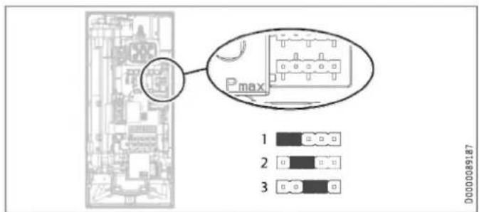
text_image
Pmax 1 2 3 D0000089187▶ Install the jumper in the required position on the pin strip.
| Jumper position | Connected load |
| 1 | 18 kW |
| 2 | 21 kW |
| 3 | 24 kW |
| No jumper | 18 kW |
11.2 Initial start-up

≥ 60 s
D0000053277
▶ Open and close all connected draw-off valves several times, until all air has been purged from the pipework and the appliance.
▶ Carry out a tightness check.
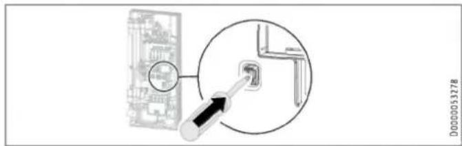
text_image
D0000053278▶ Activate the safety switch by firmly pressing the reset button (the appliance is delivered with the safety switch disabled).
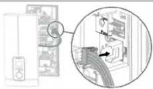
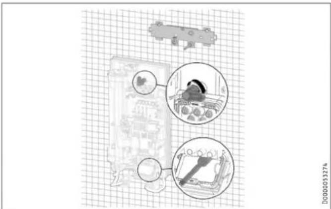
natural_image
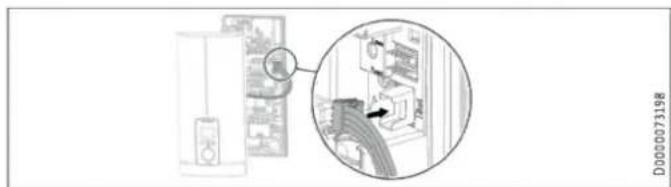
Diagram showing a refrigerator with a close-up view of the interior wall and a magnified inset of the refrigerator (no text or symbols present)D000073198
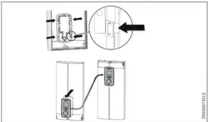
▶ Connect the programming unit connecting cable to the PCB.

Note
For undersink installation, the appliance cover should be turned round for easier operation; see chapter "Alternative installation methods / Pivoting appliance cover".
natural_image
Three sequential diagrams showing a mechanical or electrical setup with a cylindrical component and a base, no text or symbols present.D0000053280
▶ Hook the appliance cover at the top rear into the back panel. Pivot the appliance cover downwards. Check that the appliance cover is securely seated at both top and bottom.
Tick the selected connected load and rated voltage on the appliance cover type plate (on both sides). Use a ballpoint pen to do this.
▶ Secure the appliance cover with the screw.
▶ Fit the fascia to the appliance cover.
▶ Remove the protective film from the user interface.
on
D0000053281
▶ Switch on the power supply.
11.2.1 Appliance handover
Explain the appliance function to users and familiarise them with how it works.
▶ Make the user aware of potential dangers, especially the risk of scalding.
▶ Hand over the instructions.
11.3 Recommissioning

Material losses
To ensure that the bare wire heating system is not damaged following an interruption to the water supply, the appliance must be restarted by taking the following steps.
▶ Disconnect the appliance from the power supply by removing the fuses/tripping the MCBs.
▶ Open the tap for a minimum of one minute until the appliance and its upstream cold water inlet line are free of air.
▶ Switch the power back ON.
12. Appliance shutdown
▶ Isolate all poles of the appliance from the power supply.
Drain the appliance (see chapter "Installation / Maintenance / Draining the appliance").
13. Alternative installation methods
Overview of the alternative types of installation
| Electrical connection | IP rating |
| On unfinished walls, connected from above | IP 25 |
| On unfinished walls, connected from below, short power cable | IP 25 |
| On finished walls | IP 24 |
| Water connection | IP rating |
| On finished walls | IP 24 |
| Other | IP rating |
| Installation with offset tiles | IP 25 |
| Pivoting appliance cover | IP 25 |
| Horizontal installation of the appliance | IP 24 |

WARNING Electrocution
Before any work on the appliance, disconnect all poles from the power supply.
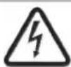
13.1 Electrical connection from above on unfinished walls
text_image
140 ≥30 1 D00000765071 Cable entry installation aid
▶ Prepare the power cable.
flowchart
graph TD
    A["Device 1"] --> B["Server"]
    C["Device 2"] --> B
    D["Device 3"] --> B
    E["Device 4"] --> B
    F["Device 5"] --> B
    G["Device 6"] --> B
    H["Device 7"] --> B
    I["Device 8"] --> B
    J["Device 9"] --> B
    K["Device 10"] --> B
    L["Central Server"] --> M["Data Packet"]
    M --> N["Data Packet"]
    N --> O["Data Packet"]
    O --> P["Data Packet"]
    P --> Q["Data Packet"]
    Q --> R["Data Packet"]
    R --> S["Data Packet"]
    S --> T["Data Packet"]
    T --> U["Data Packet"]
    U --> V["Data Packet"]
    V --> W["Data Packet"]
    W --> X["Data Packet"]
    X --> Y["Data Packet"]
    Y --> Z["Data Packet"]
    Z --> AA["Data Packet"]
    AA --> AB["Data Packet"]
    AB --> AC["Data Packet"]
    AC --> AD["Data Packet"]
    AD --> AE["Data Packet"]
    AE --> AF["Data Packet"]
    AF --> AG["Data Packet"]
    AG --> AH["Data Packet"]
    AH --> AI["Data Packet"]
    AI --> AJ["Data Packet"]
    AJ --> AK["Data Packet"]
    AK --> AL["Data Packet"]
    AL --> AM["Data Packet"]
    AM --> AN["Data Packet"]
    AN --> AO["Data Packet"]
    AO --> AP["Data Packet"]
    AP --> AQ["Data Packet"]
    AQ --> AR["Data Packet"]
    AR --> AS["Data Packet"]
    AS --> AT["Data Packet"]
    AT --> AU["Data Packet"]
    AU --> AV["Data Packet"]
    AV --> AW["Data Packet"]
    AW --> AX["Data Packet"]
    AX --> AY["Data Packet"]
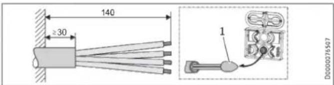
1 Cable routing
▶ Reposition the mains terminal from the bottom to the top. To do this, undo the fixing screw. Turn the mains terminal with connecting cables 180^ clockwise. Route the cable around the cable guide when doing so. Secure the mains terminal in place.
▶ Replace the cable grommets.
▶ Install the cable grommet from the top at the bottom.
▶ Pull the cable grommet over the cable sheath of the power cable.
▶ Install the appliance on the threaded studs of the wall mounting bracket.
▶ Push the back panel firmly against the wall. Lock the fixing toggle by turning it 90° clockwise.
▶ Pull the cable grommets into the back panel until both locking tabs engage.
▶ Connect the power cable to the mains terminal.

WARNING Electrocution
The connecting wires must not protrude beyond the level of the mains terminal.
13.2 Electrical connection on unfinished walls with short power cable
text_image
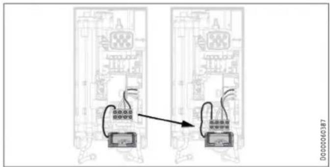
Diagram showing two electrical circuit boards connected via wires, with a directional arrow indicating connection or transformation.▶ Reposition the mains terminal further downwards. To do this, undo the fixing screw. Secure the mains terminal in place.
13.3 Electrical connection on finished walls

Note
This type of connection changes the IP rating of the appliance.
▶ Change the type plate. Cross out "IP 25" and mark the box "IP 24". Use a ballpoint pen to do this.
text_image
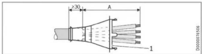
≥30 A 1 D0000765061 Cable grommet
| Electrical connection on finished walls | Dimension A |
| Positioned in lower section of appliance | 160 |
| Positioned in upper section of appliance | 110 |
▶ Prepare the power cable. Fit the cable grommet.

Material losses
If you break out the wrong knock-out in the back panel/appliance cover by mistake, you must use a new back panel/appliance cover.
▶ Cleanly cut and break out the required cable entries from the back panel and appliance cover (for the positions, see chapter "Specification / Dimensions and connections"). Deburr any sharp edges with a file.
▶ Route the power cable through the cable grommet.
▶ Connect the power cable to the mains terminal.
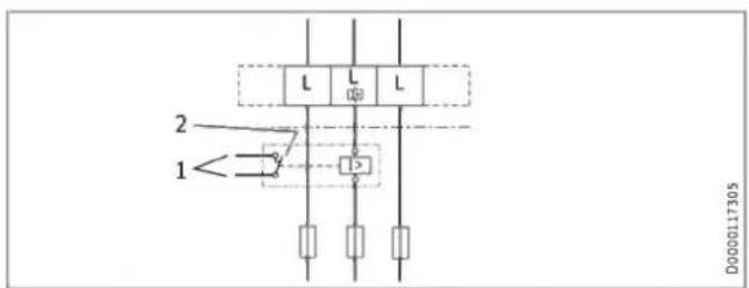
13.4 Connecting a load shedding relay
Install a load shedding relay in the distribution board in conjunction with other electric appliances, e.g. electric storage heaters. The relay responds when the instantaneous water heater starts.

Material losses
Connect the phase that switches the load shedding relay to the indicated terminal of the mains terminal in the appliance (see chapter "Specification / Wiring diagram").
13.5 Water installation on finished walls

Note
This type of connection changes the IP rating of the appliance.
▶ Change the type plate. Cross out "IP 25" and mark the box "IP 24". Use a ballpoint pen to do this.
text_image
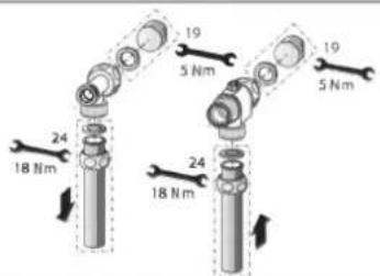
19 5 Nm 19 5 Nm 24 18 Nm 24 18 NmD000033104
▶ Fit water plugs with gaskets to seal the concealed connections. All taps obtained as accessories are supplied with plugs and gaskets as standard. For pressure taps other than those recommended by us, plugs and gaskets can be ordered as accessories.
▶ Fit a suitable pressure tap.
▶ Push the lower back panel section under the connection pipes of the tap and push it into the back panel.
- Secure the connection pipes to the tee and the 3-way ball shut-off valve.

Note
You can break off the pipe fitting tabs on the lower back panel section if required.
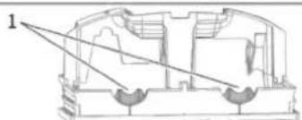
natural_image
Cross-sectional diagram of a mechanical component with labeled part 1 (no text or symbols present)D000056194
1 Tab
13.6 Water installation on finished walls with solder/press-fit fittings

Note
This type of connection changes the IP rating of the appliance.
▶ Change the type plate. Cross out "IP 25" and mark the box "IP 24". Use a ballpoint pen to do this.
You can connect copper or plastic pipes using the accessories "solder fitting" or "press-fit fitting".
With "solder fitting" with threaded fitting for 12 mm copper pipes, proceed as follows:
▶ Push the union nuts over the connection pipes.
▶ Solder the inserts to the copper pipes.
▶ Push the lower back panel section under the connection pipes of the tap and push it into the back panel.
- Secure the connection pipes to the tee and the 3-way ball shut-off valve.

Note
Observe the tap manufacturer's instructions.
13.7 Fitting appliance cover for water installation on finished walls
text_image
1 2 3 4 D0000731701 Back panel guides
2 Screw
3 Cover guides with sealing lips on the pipe side
4 Pipe knock-out
▶ Cleanly saw and break out the pipe knock-outs in the appliance cover. If necessary, use a file.
▶ Click the cover guides into place in the knock-outs.
Only if using the "solder fitting" accessory and with precise adherence to all installation dimensions:
▶ Break the sealing lips out of the cover guides.
▶ Position the back panel guides on the pipes. Push them together. Then push the guides against the back panel as far they will go.
▶ Secure the lower back panel section with a screw.

Note
You can use the cover guides with sealing lips to compensate for a slight offset of the connection pipes and/or if using the "press fitting" accessory. In this case, the back panel guides are not fitted.
13.8 Lower back panel section installation with threaded fittings on finished walls
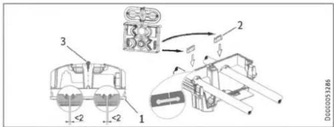
text_image
<2><2>1 Lower back panel section
2 Connection piece in the standard delivery
3 Screw
If using threaded fittings on finished walls, the lower back panel section can also be installed after fitting the taps. To do this, carry out the following steps:
▶ Cut open the lower back panel section.
▶ Fit the lower back panel section by bending it out at the sides and guiding it over the pipes.
▶ Insert the connection pieces into the lower back panel section from behind.
▶ Click the lower back panel section into place.
▶ Secure the lower back panel section with a screw.
13.9 Wall mounting bracket when replacing an appliance
An existing STIEBEL ELTRON wall mounting bracket may be used when replacing appliances (except the DHF instantaneous water heater), as long as the fixing screw is in the lower right position.
Replacing a DHF instantaneous water heater
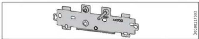
natural_image
Metallic electrical component with mounting holes and a central switch (no visible text or symbols)▶ Reposition the fixing screw on the wall mounting bracket (the fixing screw has a self-tapping thread).
▶ Rotate the wall mounting bracket 180^ and mount it on the wall (the DHF logo is then turned towards you).
13.10 Installation with offset tiles
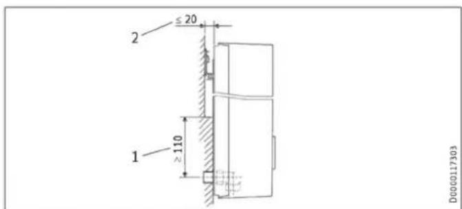
text_image
≤ 20 2 ≥ 110 1 D00001173031 Minimum contact area of the appliance
2 Maximum tile offset
▶ Adjust the wall clearance. Lock the back panel in place using the fixing toggle (turn 90° clockwise).
13.11 Pivoting appliance cover
The appliance cover should be turned round for undersink installation.
text_image
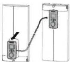
Diagram showing electrical switch installation with labeled components and connection arrowsRemove the programming unit from the appliance cover by pressing the locking hooks and removing the programming unit.
▶ Turn the appliance cover (not the appliance) the other way up and refit the programming unit. Push the programming unit home in parallel until all locking tabs engage. When engaging the locking tabs, apply counter pressure by pushing against the appliance cover from the inside.

WARNING Electrocution
All 4 locking tabs on the programming unit must click into place. The locking tabs must be complete and undamaged. If the programming unit is not inserted correctly, user protection against contact with live components cannot be ensured.
▶ Insert the connecting cable plug of the programming unit into the PCB (see chapter "Commissioning / Initial start-up").
▶ Hook the appliance cover in at the bottom. Pivot the appliance cover up to the back panel.
▶ Secure the appliance cover.
▶ Fit the cover onto the appliance cover.
13.12 Horizontal installation of the appliance

Note
For the horizontal installation alternative, please note the following points:
- Installation is only permissible with direct wall mounting. The universal mounting frame cannot be used.
- The installation versions "Installation with offset tiles" and "Rotated appliance cover" are not permissible.
- This type of connection changes the IP rating of the appliance. Cross out "IP 25" on the type plate and mark the box "IP 24". Use a ballpoint pen to do this.
Horizontal installation
The appliance can also be mounted horizontally on the wall (turned 90° to the left, with the water connections on the right). The installation, water and electrical connections are described in chapters "Standard installation" and "Alternative installation methods".
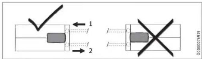
text_image
1 2 D000076919The appliance cover must be provided with a condensate drain opening of min. ∅ 5.0 mm to max. ∅ 6.0 mm at the marked position.
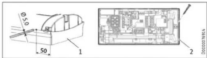
text_image
Ø5.0 50 1 2 DOC000769141 Appliance cover with opening for condensate drain
2 Back panel with additional fixing screw
▶ Drill a hole from the outside through the dismantled appliance cover at the marked point. Alternatively, you can punch a hole in the appliance cover from the inside at the marked point. In this case, you must then enlarge the hole to the required diameter from the outside. Deburr any sharp edges with a file.
▶ Secure the appliance back panel with an additional screw.

Material losses
An appliance cover with an existing condensate drain opening must no longer be used for vertical installation of the appliance.
13.13 Operation with preheated water
You can restrict the maximum inlet temperature by installing a central thermostatic valve.
14. Service information
Overview of connections
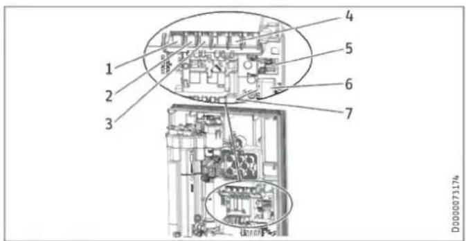
text_image
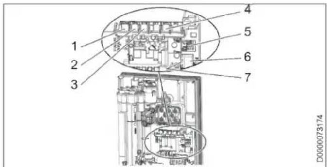
1 2 3 4 5 6 7 D00000731741 Flow limiter
2 Flow sensor
3 High limit safety cut-out, automatic reset
4 NTC sensor
5 Pin strips for connected load and anti-scalding protection
6 Programming unit plug-in position
7 Diagnostic traffic light
15. Troubleshooting

WARNING Electrocution
To test the appliance, it must be connected to the power supply.

Note
When testing the appliance using the diagnostic traffic lights, water must be flowing.
Appliance cover retainer
text_image
A 4TV 72 0 D0000056216Indicator options for diagnostic traffic light (LED)
| ●○○ | Red | Illuminates in the event of a fault |
| ○●○ | Yellow | Illuminates in heating mode/flashes when output limit reached |
| ○○● | Green | Flashing: Appliance connected to power supply |
| Diagnostic traffic Lights (draw-off mode) | Fault | Cause | Remedy |
| No LED illuminates | Appliance does not heat up | One or more mains power phases missing | Check fuses/MCBs in distribution board |
| Faulty PCB | Replacing the function module | ||
| Green flashing, yellow off, red off | No DHW | Appliance starting flow rate not reached; shower head/aerator scaled up | Descale/replace the shower head/aerator |
| Appliance starting flow rate not reached; strainer in cold water inlet dirty | Cleaning the strainer | ||
| Flow meter not attached | Check plug-in connection; correct if necessary | ||
| Flow meter faulty or dirty | Replacing the flow meter | ||
| Faulty PCB | Replacing the function module | ||
| Green flashing, yellow on, red off | No display | Loose connecting cable between PCB and programming unit | Check plug-in connections; correct if necessary |
| Faulty connecting cable between PCB and programming unit | Check connecting cable; replace if necessary | ||
| Programming unit faulty | Replacing the programming unit | ||
| Faulty PCB | Replacing the function module | ||
| Green flashing, yellow on, red off | No DHW; outlet temperature does not match set value | Tap faulty | Replace tap |
| Faulty outlet sensor | Replace the outlet sensor | ||
| Heating system faulty | Replacing the function module | ||
| Faulty PCB | Replacing the function module | ||
| Green flashing, yellow flashing, red off | No DHW; outlet temperature does not match set value | Appliance is operating at its output limit | Reduce flow rate; select one of the ECO levels |
| Appliance is operating at its output limit | Check jumper position for connected load | ||
| Heating system faulty | Replacing the function module | ||
| Green flashing, yellow off, red on | No DHW; outlet temperature does not match set value | One or more mains power phases missing | Check fuses/MCBs in distribution board |
| Air detection has responded | Continue draw-off for >1 min |
15.1 Fault code display
If there is an appliance fault, the spanner flashes on the display.
▶ To call up the fault code display, press the ECO button for more than 5 seconds.
| Diagnostic traffic lights (draw-off mode) | Display shown | Fault | Cause | Remedy |
| Green flashing, yellow off, red on | Spanner flashes (display E1 and spanner in menu "Fault code display") | No DHW; outlet temperature does not match set value | Safety switch not activated during "Commissioning" | Activate safety switch by pressing the reset button firmly |
| Safety switch triggered by high limit safety cut-out | Check high limit safety cut-out (plug-in connection, connecting cable); activate safety switch | |||
| Safety switch responds again after high limit safety cut-out has been checked; high limit safety cut-out faulty | Replace high limit safety cut-out; activate safety switch and draw off water at the maximum set value for >1 min | |||
| Safety switch responds again; PCB faulty | Replacing the function module | |||
| Green flashing, yellow off, red on | Spanner flashes (display E2 and spanner in menu "Fault code display") | No DHW | PCB faulty (lead break or short circuit in inlet sensor) | Replacing the function module |
| Green flashing, yellow off, red on | Spanner flashes (display E3 and spanner in menu "Fault code display") | No DHW | Short circuit in outlet sensor | Check outlet sensor; replace if necessary |
16. Maintenance

WARNING Electrocution
Before any work on the appliance, disconnect all poles from the power supply.
This appliance contains capacitors which are discharged when disconnected from the power supply. The capacitor discharge voltage may briefly exceed 60 V DC.
Draining the appliance
The appliance can be drained for maintenance work.

WARNING Burns
Hot water may escape when you drain the appliance.
▶ Close the 3-way ball shut-off valve or the shut-off valve in the cold water inlet line.
▶ Open all draw-off valves.
▶ Undo the pipe connections from the appliance.
▶ Store the dismantled appliance in a room free from the risk of frost, as water residues remaining inside the appliance can freeze and cause damage.
Cleaning the strainer
If dirty, clean the strainer in the threaded cold water fitting. Close the 3-way ball shut-off valve or the shut-off valve in the cold water inlet line before removing, cleaning and refitting the strainer.
17. Specification
17.1 Dimensions and connections
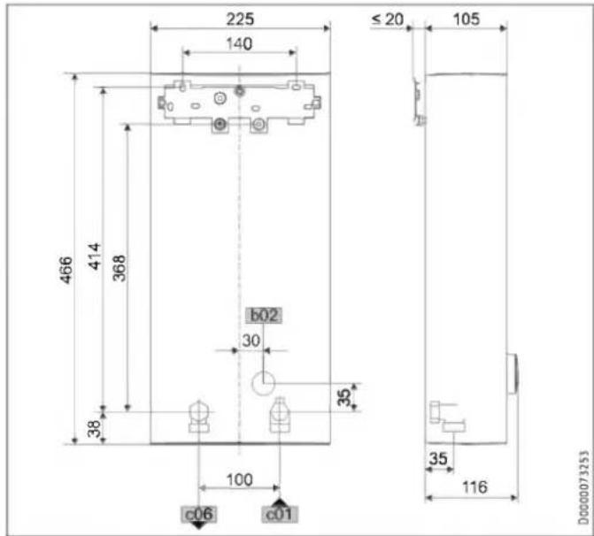
text_image
225 140 ≤ 20 105 466 414 368 b02 30 38 35 100 c06 c01 35 116 D0000073253| DEL Plus | |||
| b02 | Entry electrical cables I | On unfinished walls | |
| c01 | Cold water inlet | Male thread | G 1/2 A |
| c06 | DHW outlet | Male thread | G 1/2 A |
Alternative connection options
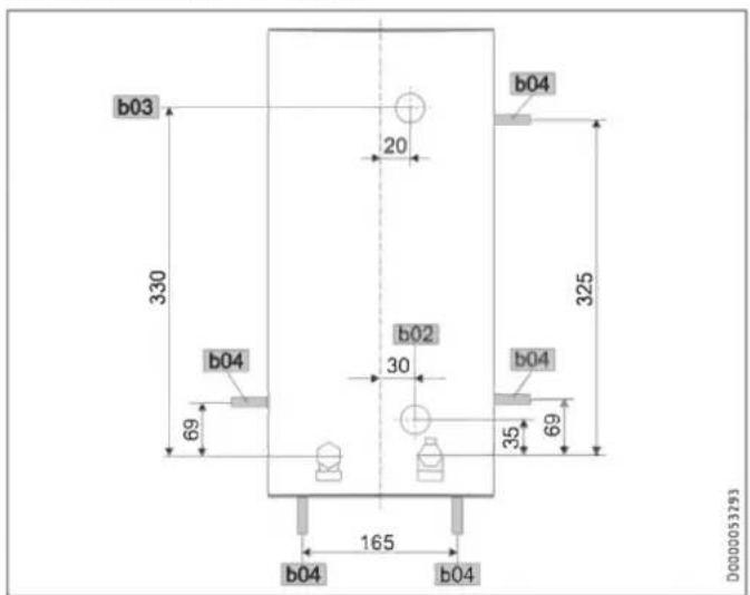
text_image
b03 330 b04 69 b02 30 b04 325 35 69 b04 165 b04 b04 D0000053793| DEL Plus | |||
| b02 | Entry electrical cables I | On unfinished walls | |
| b03 | Entry electrical cables II | On unfinished walls | |
| b04 | Entry electrical cables III | On finished walls | |
17.2 Wiring diagram
3/PE \~ 380-415 V
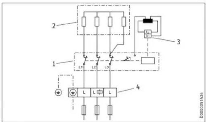
text_image
2 1 L1 L2 L3 4 D00000514241 Power PCB with integral safety switch
2 Bare wire heating system
3 High limit safety cut-out
4 Mains terminal
Priority control with load shedding relay LR 1-A
text_image
2 11 Control cable to the contactor of the second appliance (e.g. electric storage heater)
2 Control contact drops out when switching the instantaneous water heater on.
Material losses
If the appliance is replaced, also replace the load shedding relay and contactor of the 2nd appliance.
17.3 DHW output
The DHW output is subject to the connected power supply, the appliance's connected load and the cold water inlet temperature. The rated voltage and rated output can be found on the type plate.
| Connected load in kW | 38 °C DHW output in L/min | |||||
| Rated voltage | Cold water inlet temperature | |||||
| 380 V | 400 V | 415 V | 5 °C | 10 °C | 15 °C | 20 °C |
| DEL 18/21/24 Plus | ||||||
| 16.2 | 7.0 | 8.3 | 10.1 | 12.9 | ||
| 19 | 8.2 | 9.7 | 11.8 | 15.1 | ||
| 21.7 | 9.4 | 11.1 | 13.5 | 17.2 | ||
| 18 | 7.8 | 9.2 | 11.2 | 14.3 | ||
| 21 | 9.1 | 10.7 | 13.0 | 16.7 | ||
| 24 | 10.4 | 12.2 | 14.9 | 19.0 | ||
| 19.4 | 8.4 | 9.9 | 12.0 | 15.4 | ||
| 22.6 | 9.8 | 11.5 | 14.0 | 17.9 | ||
| 25.8 | 11.2 | 13.2 | 16.0 | 20.5 | ||
| DEL 27 Plus | ||||||
| 24.4 | 10.6 | 12.4 | 15.2 | 19.4 | ||
| 27 | 11.7 | 13.8 | 16.8 | 21.4 | ||
| Connected load in kW | 50 °C DHW output in L/min | |||||
| Rated voltage | Cold water inlet temperature | |||||
| 380 V | 400 V | 415 V | 5 °C | 10 °C | 15 °C | 20 °C |
| DEL 18/21/24 Plus | ||||||
| 16.2 | 5.1 | 5.8 | 6.6 | 7.7 | ||
| 19 | 6.0 | 6.8 | 7.8 | 9.0 | ||
| 21.7 | 6.9 | 7.8 | 8.9 | 10.3 | ||
| 18 | 5.7 | 6.4 | 7.3 | 8.6 | ||
| 21 | 6.7 | 7.5 | 8.6 | 10.0 | ||
| 24 | 7.6 | 8.6 | 9.8 | 11.4 | ||
| 19.4 | 6.2 | 6.9 | 7.9 | 9.2 | ||
| 22.6 | 7.2 | 8.1 | 9.2 | 10.8 | ||
| 25.8 | 8.2 | 9.2 | 10.5 | 12.3 | ||
| DEL 27 Plus | ||||||
| 24.4 | 7.7 | 8.7 | 10.0 | 11.6 | ||
| 27 | 8.6 | 9.6 | 11.0 | 12.9 | ||
17.4 Application areas / Conversion table
Specific electrical resistance and specific electrical conductivity
| Standard specification at 15 °C | 20 °C | 25 °C | ||||||
| Resistivity ≥ | Conductivity ≤ | Resistivity ≥ | Conductivity ≤ | Resistivity ≥ | Conductivity ≤ | |||
| mS/m | μS/cm | mS/m | μS/cm | mS/m | μS/cm | |||
| 900 | 111 | 1111 | 800 | 125 | 1250 | 735 | 136 | 1361 |
17.5 Pressure drop
Taps
| Tap pressure drop at a flow rate of 10 L/min | ||
| Mono lever mixer tap, approx. | MPa | 0.04 - 0.08 |
| Thermostatic valve, approx. | MPa | 0.03 - 0.05 |
| Shower head, approx. | MPa | 0.03 - 0.15 |
Sizing the pipework
When calculating the size of the pipework, an appliance pressure drop of 0.1 MPa is recommended.
17.6 Fault conditions
In the event of a fault, loads up to 80 °C at a pressure of 1.0 MPa can occur briefly in the installation.
17.7 Energy consumption data
Product datasheet: Conventional water heaters to regulation (EU) no. 812/2013 and 814/2013 / (S.I. 2019 No. 539 / Schedule 2)
| DEL 18/21/24 Plus | DEL 27 Plus | ||
| 236739 | 236740 | ||
| Manufacturer | STIEBEL ELTRON | STIEBEL ELTRON | |
| Load profile | S | S | |
| Energy efficiency class | A | A | |
| Energy conversion efficiency | % | 39 | 39 |
| Annual power consumption | kWh | 476 | 475 |
| Default temperature setting | °C | 60 | 60 |
| Sound power level | dB(A) | 15 | 15 |
| Special information on measuring efficiency | Measured at ECO level at highest flow rate, maximum output and maximum set value. | Measured at ECO level at highest flow rate and maximum set value | |
| Daily power consumption | kWh | 2.184 | 2.177 |
17.8 Data table
| DEL 18/21/24 Plus | DEL 27 Plus | |||||
| 236739 | 236740 | |||||
| Electrical data | ||||||
| Rated voltage | V | 380 | 400 | 415 | 380 | 400 |
| Rated output | kW | 16.2/19/21.7 | 18/21/24 | 19.4/22.6/25.8 | 24.4 | 27 |
| Rated current | A | 27.6/29.5/33.3 | 29/31/35 | 30.1/32.2/36.3 | 37.1 | 39 |
| Fuse protection | A | 32/32/35 | 32/32/35 | 32/32/40 | 40 | 40 |
| Frequency | Hz | 50/60 | 50/60 | 50/- | 50/- | 50/- |
| Phases | 3/PE | 3/PE | ||||
| Specific resistivity 15 ≥ | Ω cm | 900 | 900 | |||
| Specific conductivity 15 ≤ | μS/cm | 1111 | 1111 | |||
| Max. mains impedance | Ω | 0.247 | 0.235 | 0.226 | 0.220 | 0.209 |
| Versions | ||||||
| Heating system heat generator | Bare wire | Bare wire | ||||
| Adjustable connected load | X | - | ||||
| Temperature settings | °C | Off, 20-60 | Off, 20-60 | |||
| Protection class | 1 | 1 | ||||
| Insulating block | Plastic | Plastic | ||||
| Cover and back panel | Plastic | Plastic | ||||
| IP rating | IP25 | IP25 | ||||
| Colour | White | White | ||||
| Connections | ||||||
| Water connection | G 1/2 A | G 1/2 A | ||||
| Application limits | ||||||
| Max. permissible pressure | MPa | 1 | 1 | |||
| Max. inlet temperature for reheating | °C | 55 | 55 | |||
| DEL 18/21/24 Plus | DEL 27 Plus | ||
| Values | |||
| Max. inlet temperature (e.g. pasteurisation) | °C | 70 | 70 |
| ON | l/min | >2.5 | >2.5 |
| Flow rate at 28 K | l/min | 9.2/10.7/12.3 at 400 V | 13.8 at 400 V |
| Flow rate at 50 K | l/min | 5.2/6.0/6.9 at 400 V | 7.7 at 400 V |
| Pressure drop for flow rate at 50 K (without flow limiter) | MPa | 0.06/0.08/0.1 | 0.13 |
| Hydraulic data | |||
| Nominal capacity | l | 0.4 | 0.4 |
| Dimensions | |||
| Height | mm | 466 | 466 |
| Width | mm | 225 | 225 |
| Depth | mm | 116 | 116 |
| Weights | |||
| Weight | kg | 3.2 | 3.2 |

Note
The appliance conforms to IEC 61000-3-12.
Information on the appliance software
Stiebel Eltron appliances may contain software of external suppliers (third party suppliers) which may be partly also be subject to an Open Source license. Some Open Source licenses are subject to the obligation to state the software, its authors as well as the licenses that apply to the software and to additionally provide the software as a source code or to offer to provide the source code. Stiebel Eltron therefore provides further information regarding third supplier software that it uses under the link https://www.stiebel-eltron.com/en/info/Licenses.html and also offers the source code there, if applicable. The software is provided only for compliance with the obligations under the Open Source licenses.
Guarantee
The guarantee conditions of our German companies do not apply to appliances acquired outside of Germany. In countries where our subsidiaries sell our products a guarantee can only be issued by those subsidiaries. Such guarantee is only granted if the subsidiary has issued its own terms of guarantee. No other guarantee will be granted.
We shall not provide any guarantee for appliances acquired in countries where we have no subsidiary to sell our products. This will not affect warranties issued by any importers.
Environment and recycling
▶ Dispose of the appliances and materials after use in accordance with national regulations.

If a crossed-out waste bin is pictured on the appliance, take the appliance to your local waste and recycling centre or nearest retail take-back point for reuse and recycling.
This document is made of recyclable paper. ▶ Dispose of the document at the end of the appliance's life cycle in accordance with national regulations.
REMARQUES PARTICULIÈRES
UTILISATION
9.3 Installation hydraulique
natural_image
Three technical diagrams showing a cylindrical object being inserted into a container, with arrows indicating direction (no text or symbols present)natural_image
Technical line drawing of two mechanical components with directional arrows indicating motion (no text or symbols)natural_image
Technical drawing of a mechanical component with mounting holes and directional arrows, displayed on grid background (no readable text or symbols)text_image
Diagram showing three labeled mechanical components with arrows indicating direction, likely illustrating a assembly or manufacturing process.D000053291
natural_image
Illustration of a computer monitor with two circular insets showing close-ups of the screen and a keyboard (no text or symbols present)D000005327%
natural_image
Mechanical assembly diagram showing a bracket with directional arrows indicating motion (no text or labels)D0000053275
text_image
Diagram showing a magnified view of a component being inserted into a wall, with an arrow indicating the insertion direction.D0000053278
natural_image
Diagram showing a server rack connected to an electrical cabinet with a magnified inset highlighting internal components (no text or symbols present)text_image
Diagram showing two electrical or circuitry setups with labeled components and wiring connections, including a directional arrow indicating connection.natural_image
Cross-sectional diagram of a mechanical component with labeled part 1 (no text or symbols present)D0000056194
1 Languette
natural_image
Mechanical component with mounting holes and a central shaft (no visible text or symbols)text_image
Diagram showing a device with directional arrows and an inset close-up of the internal structure, likely illustrating a mechanical or electrical component assembly.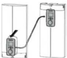
text_image
Diagram showing two connected devices with a labeled connection point, likely illustrating a measurement or system setup.D0000073012
text_image
Diagram showing a checkmark inside a rectangular box with arrows labeled 1 and 2 pointing to internal components.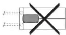
00000076919
text_image
Ø 5.0 50 1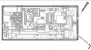
natural_image
Architectural floor plan diagram with labeled components (no text or symbols)0000076914
natural_image
Architectural floor plan showing room layouts and equipment layout (no text or labels)natural_image
Three sequential diagrams showing a cylindrical object being placed on a base, with arrows indicating motion (no text or symbols)natural_image
Mechanical assembly diagram showing two views of a vehicle or engine component with no visible text or symbolsnatural_image
Technical diagram of a mechanical component with mounting holes and internal features, displayed on grid paper (no text or symbols)text_image
Diagram showing mechanical assembly steps with labeled components 1 and 2, including a tool and component layout.D0000053291
text_image
Technical diagram showing a mechanical assembly with three circular insets highlighting different components, likely for engineering or manufacturing documentation.natural_image
Diagram showing a device with an inset close-up of internal components, no visible text or symbols▶ Steek de verbindingskabel van de bedieningseenheid op de elektronica.

Aanwijzing
natural_image
Three sequential diagrams showing a cylindrical object being inserted into a container, with an arrow indicating the process (no text or symbols present)natural_image
Metal mechanical component with mounting holes and a central knob (no text or symbols visible)text_image
Technical diagram showing a mechanical assembly with directional arrows and a magnified detail view highlighting a specific component.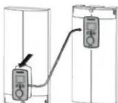
natural_image
Diagram showing two connected devices with a cable, no text or symbols presentD0000073012
text_image
Diagram showing a checkmark inside a rectangular box with arrows labeled 1 and 2 pointing to internal dotted lines.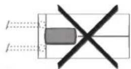
D0000076919
1 Koudwatertoevoer
2 Warmwateruitloop
Voorbereiding
text_image
Technical diagram of an electronic device floor plan with labeled components and annotationsD0000076914
natural_image
Floor plan diagram of a residential area with furniture layout and a central device (no text or labels visible)15. Storingen verhelpen

WAARSCHUWING elektrische schok
text_image
Technical diagram of an electronic device with numbered components, highlighting internal circuitry and wiring layout.D0000073174
1 محدد كمية الدفق
2 مستشر كمية الدفق
6Market making, a 100% market making
7 إشارة التخillis
natural_image
Architectural floor plan showing room layouts and a cylindrical device (no text or labels)D0000056216
text_image
1 2 3 4 5 6 7 D0000073174
text_image
Diagram showing a checkmark and two arrows labeled 1 and 2 pointing to a rectangular object with dashed lines indicating alignment or flow.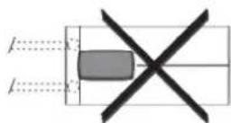
D0000076919
1 مدخل الماء البارد
2 مخرج الماء الساخن
الإعداد
natural_image
Architectural floor plan diagram showing room layouts and structural elements (no text or labels)D0000076914
text_image
Technical diagram showing a mechanical assembly with directional arrows and a magnified detail view highlighting a component with diameter 4.4.D0000073012
natural_image
Diagram showing two connected devices with a cable and a pointer, no text or symbols presenttext_image
Technical diagram of a vehicle's internal components with numbered parts and directional arrows indicating assembly or movement.D0000053286
natural_image
Technical line drawing of a mechanical component with no visible text or symbolsD0000056194
1 LAN
text_image
Diagram showing connections between electrical connectors and a central device, with labeled components and wiring paths.D0000053282
1 تمير الكتاب
natural_image
Diagram showing a server rack connected to an electrical cabinet with a magnified inset highlighting internal components (no text or symbols present)natural_image
Three sequential diagrams showing a container with internal components, one being inserted and the other being added to a base (no text or symbols)natural_image
Mechanical assembly diagram showing a component with directional arrows, no readable text or symbols presentD0000053275
text_image
Diagram showing mechanical assembly steps with labeled components 1 and 2D0000053291
natural_image
Diagram of a mechanical device with two circular insets showing internal components (no text or labels)D0000053274
natural_image
Technical drawing of a mechanical component with mounting holes and mounting points, displayed on grid paper (no text or symbols)natural_image
Three technical diagrams showing a cylindrical device with internal components, arranged in a row (no text or symbols present)natural_image
Technical illustration of two mechanical components with directional arrows, no visible text or symbolstext_image
Technical diagram of a bathroom sink with labeled components and directional arrows indicating flow or movement.
1 مدخل الماء الارد
2 مخرج الماء الساخن
التركيب المعلق
1 مدخل الماء البارد
2 مخرج الماء الساخن
ملحوظة

natural_image
Technical line drawing of a mechanical device with an inset showing a close-up view of a component (no text or symbols present)D0000053312
ECO--acctير وضع 4.8