
AXXIO 36230 Q - Grinder EINHELL - Free user manual and instructions
Find the device manual for free AXXIO 36230 Q EINHELL in PDF.
| Product type | Cordless angle grinder |
| Brand | Einhell |
| Model | AXXIO 36230 Q |
| Supply voltage | 36 V DC |
| Spindle thread | M14 |
| Weight | 4.2 kg |
| Battery type | Lithium-ion (Power-X-Change) |
| Recommended battery capacity | 4.0 Ah (ref. 45.113.96) |
| Max wheel diameter | Not specified, but compatible with wheels up to 125 mm (estimate) |
| No-load speed | Approx. 8,500 rpm (estimate) |
| Main functions | Grinding, cutting, roughing |
| Guard | Tool-free adjustable, for grinding and cutting |
| Auxiliary handle | 3 positions (left, right, top) |
| Rotating handle | Rotation ±90° |
| Spindle lock | Yes, for disc change |
| Safety switch | Yes, anti-restart |
| Battery charge indicator | 3 LEDs |
| Sound pressure level (LpA) | 88.35 dB(A) |
| Sound power level (LwA) | 99.35 dB(A) |
| Vibration (main handle) | 5.490 m/s² (K=1.5 m/s²) |
| Vibration (auxiliary handle) | 9.636 m/s² (K=1.5 m/s²) |
| Maintenance | Regular cleaning of ventilation slots; no internal maintenance |
| Included accessories | Auxiliary handle, quick-release nut, flange nut wrench, guard |
| Warranty | 24 months |
Frequently Asked Questions - AXXIO 36230 Q EINHELL
User questions about AXXIO 36230 Q EINHELL
0 question about this device. Answer the ones you know or ask your own.
Ask a new question about this device
Download the instructions for your Grinder in PDF format for free! Find your manual AXXIO 36230 Q - EINHELL and take your electronic device back in hand. On this page are published all the documents necessary for the use of your device. AXXIO 36230 Q by EINHELL.
USER MANUAL AXXIO 36230 Q EINHELL
GB Original operating instructions Cordless Angle Grinding
When using the equipment, a few safety precautions must be observed to avoid injuries and damage. Please read the complete operating instructions and safety regulations with due care. Keep this manual in a safe place, so that the information is available at all times. If you give the equipment to any other person, hand over these operating instructions and safety regulations as well. We cannot accept any liability for damage or accidents which arise due to a failure to follow these instructions and the safety instructions.
Explanation of the symbols used (see Fig. 17)
- Danger! - Read the operating instructions to reduce the risk of injury.
- Caution! Wear ear-muffs. The impact of noise can cause damage to hearing.
- Caution! Wear a breathing mask. Dust which is injurious to health can be generated when working on wood and other materials. Never use the device to work on any materials containing asbestos!
- Caution! Wear safety goggles. Sparks generated during working or splinters, chips and dust emitted by the device can cause loss of sight.
- Store the batteries only in dry rooms with an ambient temperature of +10^ to +40^ . Place only fully charged batteries in storage (charged at least 40% ).
- This safety guard is designed for sand- ding/grinding.
- This safety guard is designed for cutting and grinding/sanding.
1. Safety regulations
The corresponding safety information can be found in the enclosed booklet.
Warning!
Read all the safety information, instructions, illustrations and technical data provided on or with this power tool. Failure to adhere to the following instructions may result in electric shock, fire and/or serious injury.
Keep all the safety information and instructions in a safe place for future use.
2. Layout and items supplied
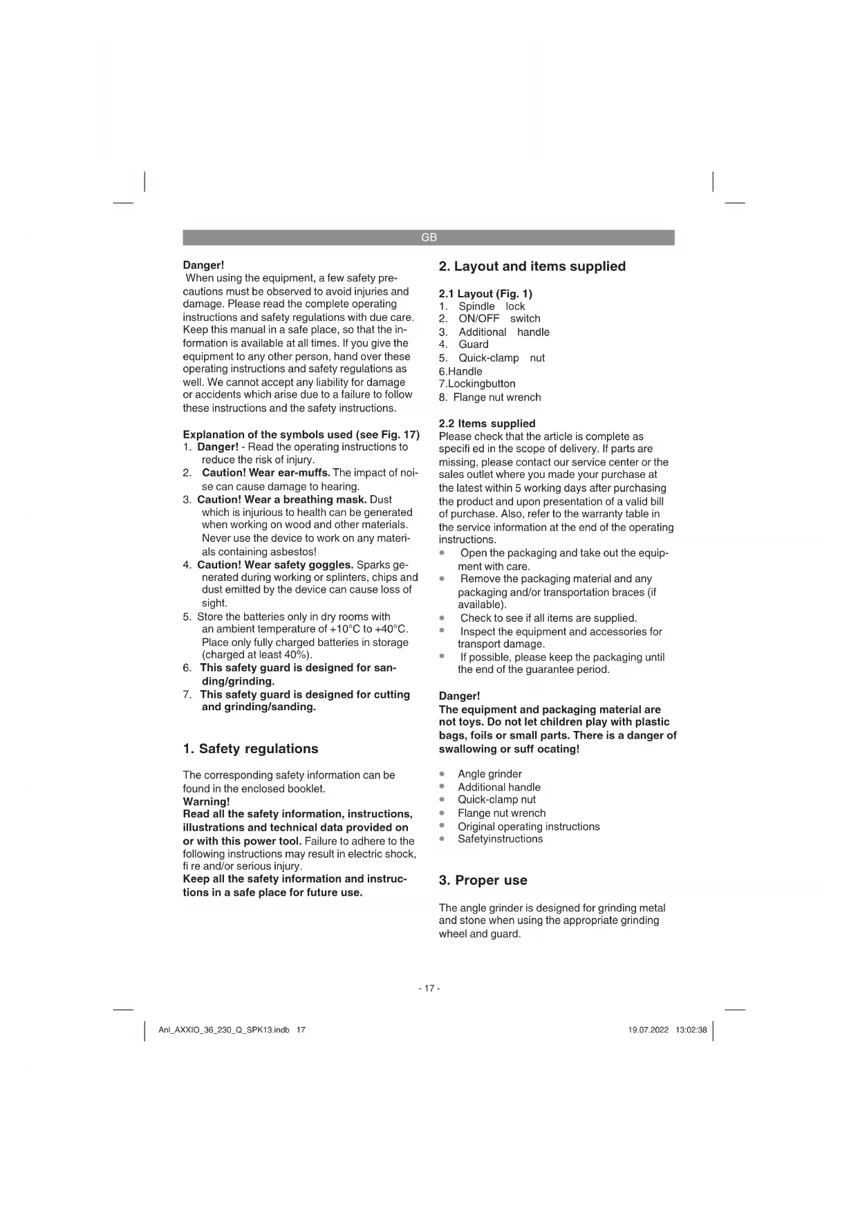
2.1 Layout (Fig. 1)
- Spindle lock
- ON/OFF switch
- Additional handle
- Guard
- Quick-clamp nut 6.Handle
7.Lockingbutton - Flange nut wrench
2.2 Items supplied
Please check that the article is complete as specified in the scope of delivery. If parts are missing, please contact our service center or the sales outlet where you made your purchase at the latest within 5 working days after purchasing the product and upon presentation of a valid bill of purchase. Also, refer to the warranty table in the service information at the end of the operating instructions.
- Open the packaging and take out the equipment with care.
- Remove the packaging material and any packaging and/or transportation braces (if available).
- Check to see if all items are supplied.
- Inspect the equipment and accessories for transport damage.
If possible, please keep the packaging until the end of the guarantee period.
Danger!
The equipment and packaging material are not toys. Do not let children play with plastic bags, foils or small parts. There is a danger of swallowing or suffocating!
Angle grinder
Additional handle
Quick-clamp nut
Flange nut wrench
Original operating instructions
- Safetyinstructions
3. Proper use
The angle grinder is designed for grinding metal and stone when using the appropriate grinding wheel and guard.
GB
Warning! To cut metal and stone the grinder/san-der may only be used when the guard (available as an accessory) is mounted.
The equipment is to be used only for its prescribed purpose. Any other use is deemed to be a case of misuse. The user / operator and not the manufacturer will be liable for any damage or injuries of any kind caused as a result of this.
Please note that our equipment has not been designed for use in commercial, trade or industrial applications. Our warranty will be voided if the machine is used in commercial, trade or industrial businesses or for equivalent purposes.
4. Technical data
Motor power supply: 36 V DC
Rated speed: 6600 min-1
Max.wheel diameter: 230 mm
Mounting spindle thread: M14
Weight: 4.2 kg
Danger!
Sound and vibration
Sound and vibration values were measured in accordance with EN 60745.
LpA sound pressure level 88.35 dB(A)
K_DA uncertainty 3 dB
L_WA sound power level 99.35 dB(A)
K_WA uncertainty 3 dB
Wear ear-muff s.
The impact of noise can cause damage to hearing.
Total vibration values (vector sum of three directions) determined in accordance with EN 60745.
Handle
Vibration emission value a_hAg = 5.490 m/s^2
K uncertainty = 1.5m / s^2
Additional handle
Vibration emission value a_hAG = 9.636 m/s^2
Kuncertainty = 1.5m / s^2
The stated vibration emission levels and stated noise emission values were measured in accordance with a set of standardized criteria and
can be used to compare one power tool with another.
The stated vibration emission levels and stated noise emission values can also be used to make an initial assessment of exposure.
Warning:
The vibration and noise emission levels may vary from the level specified during actual use, depending on the way in which the power tool is used, especially the type of workpiece it is used for.
Keep the noise emissions and vibrations to a minimum.
- Only use appliances which are in perfect working order.
Service and clean the appliance regularly.
Adapt your working style to suit the appliance.
Do not overload the appliance. - Have the appliance serviced whenever necessary.
- Switch the appliance off when it is not in use.
Caution!
Residual risks
Even if you use this electric power tool in accordance with instructions, certain residual risks cannot be rules out. The following hazards may arise in connection with the equipment's construction and layout:
- Lung damage if no suitable protective dust mask is used.
- Damage to hearing if no suitable ear protection is used.
- Health damage caused by hand-arm vibrations if the equipment is used over a prolonged period or is not properly guided and maintained.
5. Before starting the equipment
Warning!
Always remove the battery pack before making adjustments to the equipment.
5.1 Fitting the additional handle (Fig. 2)
The angle grinder must not be used without the additional handle (3).
The additional handle can be secured in any of three positions (A, B, C).
GB
| Tool side Suitable for | |
| Left (position A / as shown) | Right-handedusers |
| Right(positionB)Left-handedusers | |
| Top (position C) Using | cutting wheels |
5.2 Replacing and adjusting the guard (Fig. 3)
Replacing:
- Remove the quick-clamp nut (5)/ flange nut (a) and the clamping flange underneath.
- Open the clamp lever (a) on the guard (4).
- Turn the guard (4) through 180^ in clockwise direction so that the guard points upwards.
- Remove the guard (4).
To mount, proceed in the reverse order.
Adjusting:
- Adjust the guard (4) to protect your hands so that the material being ground is directed away from your body.
The position of the guard (4) can be adjusted to any specific working conditions. Undo the clamp handle (a) and turn the cover (4) into the required position. - Ensure that the guard (4) correctly covers the gear wheel casing.
- Secure the clamp handle (a) again.
Ensure that the guard (4) is secure.
Warning!
Make sure that the guard is perfectly secure.
Warning!
Never use the angle grinder without the guard.
5.3 Swivel handle (Fig. 4)
The handle can be swiveled a maximum 90^ to the left and right. To do so, press the locking plate (7) and swivel the handle 90^ to the left or right. Important. When the locking plate (7) engages correctly it makes an audible click.
6. Operation
6.1 Charging the Li battery pack (Fig. 5-6)
- Remove the battery pack (b) from the handle, pressing the pushlock button (c) downwards to do so.
- Check that your mains voltage is the same as that marked on the rating plate of the battery charger. Insert the power plug of the charger (d) into the mains socket outlet. The green LED will then begin to flash.
- Push the battery pack onto the battery charger.
In section 10 (Charger indicator) you will find a table with an explanation of the LED indicator on the charger.
If the battery pack fails to charge, check for the following:
- voltage at the power socket
whether there is good contact at the charging contacts of the charging unit
If the battery pack still fails to charge, send
the charger and charging adapter
and the battery pack
to our customer service center.
To ensure that items are properly packaged and delivered when you send them to us, please contact our customer service or the point of sale at which the equipment was purchased.
When shipping or disposing of batteries and cordless tools, always ensure that they are packed individually in plastic bags to prevent short circuits and fi res.
To ensure that the battery pack provides long service, you should take care to recharge it promptly. You must recharge the battery pack when you notice that the performance of the device drops. Never allow the battery pack to become fully discharged. This will cause it to develop a defect.
6.2 Switch (Fig. 7)
The angle grinder comes with a safety switch which is designed to prevent accidents. To start the equipment push the locking lever (a) forwards, then press the ON/OFF switch (3).
GB
Important!
Following a stoppage (due to overloading), the cordless equipment starts up again automatically.
Important!
Wait until the machine has reached its top speed. You can then position the angle grinder on the workpiece and machine it.
6.3 Battery capacity indicator (Fig. 8)
Press the battery capacity indicator switch (f). The battery capacity indicator (e) shows the charge status of the battery using 3 LEDs.
All 3 LEDs are lit:
The battery is fully charged.
2 or 1 LED(s) are lit:
The battery has an adequate remaining charge.
1 LED fl ashes:
The battery is empty, recharge the battery.
All LEDs blink:
The battery temperature is too low. Remove the battery from the equipment, keep it at room temperature for one day. If the fault reoccurs, this means that the rechargeable battery has undergone exhaustive discharge and is defective. Remove the battery from the equipment. Never use or charge a defective battery.
6.4 Changing the grinding wheels (Fig. 9-14)
The angle grinder is supplied with a quick-clamp nut as well as with a conventional flange nut and face spanner.
Quick-clamp nut
Danger! For safety reasons the quick-clamp nut is allowed to be used only for roughing wheels.
The wheel is easy to change using the spindle lock and quick-clamp nut.
- Press the spindle lock and allow the grinding wheel to engage.
- Undo the quick-clamp nut by turning it counterclockwise by hand (see Fig. 9).
- Change the grinding wheel or cutting wheel and tighten the quick-clamp nut by turning it clockwise by hand.
Warning!
The quick-clamp nut must be well tightened in order to prevent it from working itself loose during
use! This can be done by turning the grinding wheel clockwise with a strong tug while keeping the spindle lock pressed! While you are doing this, wear gloves to prevent injury.
Warning!
For safety reasons the quick-clamp nut (5) may only be used for this angle grinder.
Notice!
Only ever press the spindle lock when the motor and grinding spindle are at a standstill! You must keep the spindle lock pressed while you change the wheel!
Flange nut
The flange nut is allowed to be used with grinding and cutting wheels.
Use the supplied face spanner (8) to change the grinding wheels.
Danger!
For safety reasons, the angle grinder must not be operated with the face spanner (8) inserted in it.
Simple wheel change by spindle lock:
- Press the spindle lock and allow the grinding wheel to latch in place.
- Open the flange nut with the face spanner. (Fig. 10)
- Change the grinding or cutting wheel and tighten the flange nut with the face spanner.
6.5 Flange arrangements when using grinding wheels and cutting wheels (Fig. 11-14)
- Flange arrangement when using a depressed-centre or straight grinding wheel (Fig. 12)
a) Clamping flange
b) Flange nut
- Flange arrangement when using a depressed-centre cutting wheel (Fig. 13)
a) Clamping flange
b) Flange nut
- Flange arrangement when using a straight cutting wheel (Fig. 14)
a) Clamping flange
b) Flange nut
6.6 Test run for new grinding Wheels
Allow the right-angle grinder to run in idle for at least 1 minute with the grinding or cutting wheel fitted in place. Vibrating wheels are to be replaced immediately.
GB
6.7 Grinding Wheels
- Never use a grinding or cutting wheel bigger than the specified diameter.
Before using a grinding or cutting wheel, check its rated speed.
The maximum speed of the grinding or cutting wheel used must be higher than the idle speed of the angle grinder.
Use only grinding and cutting wheels that are approved for a minimum speed of 6,600 rpm and a peripheral speed of 80m / sec - Check the direction of rotation when you use diamond cutting wheels. The directional arrow on the diamond cutting wheel must point in the direction in which the tool rotates.
Warning!
Take special care that the grinding/sanding wheels are properly stored and transported. Ensure that the grinding/sanding wheels are never exposed to shock, jolts or sharp edges (for example during transport or storage in a toolbox). This could cause damage (such as cracks) to the grinding/sanding wheels and place the user in serious danger.
Warning!
6.8 Operating Modes
6.8.1 Rough grinding (Fig. 15)
Caution: Use the safety device for sanding/ grinding
For the best rough grinding results, hold the grinding wheel at an angle of between 30^ and 40^ to the workpiece surface and guide back and forth over the workpiece in steady movements.
6.8.2 Cutting (Fig. 16)
Caution: Use the safety device for abrasive cutting (available as accessory, see 7.3)
Important! Use only with the fl ange nut! When you use the right-angle grinder for cutting purposes, avoid tilting it in the cutting plane. The cutting wheel must have a clean cutting edge. A diamond cutting wheel is best used to cut hard stone.
6.9 Motor
It is vital for the motor to be well ventilated during operation. Be sure, therefore, to keep the ventilation holes clean at all times.
Warning!
Take special care that the grinding/sanding wheels are properly stored and transported.
Ensure that the grinding/sanding wheels are never exposed to shock, jolts or sharp edges (for example during transport or storage in a toolbox). This could cause damage (such as cracks) to the grinding/sanding wheels and place the user in serious danger.
Warning!
It is prohibited to use the machine on asbestos materials!
Warning!
Never use a cutting wheel for rough grinding.
Note:
To increase the power and running time of the cordless equipment, we recommend using our 4.0 Ah Power-X-Change.
(Art.No.:45.113.96)
7. Cleaning, maintenance and ordering of spare parts
Danger!
Always pull out the battery pack before starting any cleaning work.
7.1 Cleaning
- Keep all safety devices, air vents and the motor housing free of dirt and dust as far as possible. Wipe the equipment with a clean cloth or blow it with compressed air at low pressure.
We recommend that you clean the device immediately each time you have finished using it.
Clean the equipment regularly with a moist cloth and some soft soap. Do not use cleaning agents or solvents; these could attack the plastic parts of the equipment. Ensure that no water can seep into the device. The ingress of water into an electric tool increases the risk of an electric shock.
7.2 Maintenance
There are no parts inside the equipment which require additional maintenance.
GB
7.3 Ordering replacement parts:
Please quote the following data when ordering replacement parts:
Type of machine
Article number of the machine
- Identification number of the machine
- Replacement part number of the part required
For our latest prices and information please go to www.Einhell-Service.com
Safety guard for cutting (Art. No.: 44.500.56)
8. Disposal and recycling
The equipment is supplied in packaging to prevent it from being damaged in transit. The raw materials in this packaging can be reused or recycled. The equipment and its accessories are made of various types of material, such as metal and plastic. Never place defective equipment in your household refuse. The equipment should be taken to a suitable collection center for proper disposal. If you do not know the whereabouts of such a collection point, you should ask in your local council offices.
9. Storage
Store the equipment and accessories in a dark and dry place at above freezing temperature. The ideal storage temperature is between 5 and 30^ . Store the electric tool in its original packaging.
10. Charger indicator
| Indicator status | Explanations and actions | |
| Red LED Green LED | ||
| Off | Flashing | Ready for use The charger is connected to the mains and is ready for use; there is no battery pack in the charger |
| On Off Charging | The charger is charging the battery pack in quick charge mode. The charging times are shown directly on the charger. Important! The actual charging times may vary slightly from the stated charging times depending on the existing battery charge. | |
| Off | On | The battery is charged and ready for use. (READY TO GO) The unit then changes over to gentle charging mode until the battery is fully charged. To do this, leave the rechargeable battery on the charger for approx. 15 minutes longer. Action: Take the battery pack out of the charger. Disconnect the charger from the mains supply. |
| Flashing Off | Adapted charging | |
| The charger is in gentle charging mode. For safety reasons the charging is performed less quickly and takes more time. The reasons can be: - The rechargeable battery has not been used for a very long time. - The battery temperature is outside the ideal range. Action: Wait for the charging to be completed; you can still continue to charge the battery pack. | ||
| Flashing Flashing Fault | Charging is no longer possible. The battery pack is defective. Action: Never charge a defective battery pack. Take the battery pack out of the charger. | |
| On On Temperature fault | The battery pack is too hot (e.g. due to direct sunshine) or too cold (below 0°C). Action: Remove the battery pack and keep it at room temperature (approx. 20°C) for one day. | |
GB

For EU countries only
Never place any electric power tools in your household refuse.
To comply with European Directive 2012/19/EC concerning old electric and electronic equipment and its implementation in national laws, old electric power tools have to be separated from other waste and disposed of in an environment-friendly fashion, e.g. by taking to a recycling depot.
Recycling alternative to the return request:
As an alternative to returning the equipment to the manufacturer, the owner of the electrical equipment must make sure that the equipment is properly disposed of if he no longer wants to keep the equipment. The old equipment can be returned to a suitable collection point that will dispose of the equipment in accordance with the national recycling and waste disposal regulations. This does not apply to any accessories or aids without electrical components supplied with the old equipment.
Please note that batteries and lamps (e.g. light bulbs) must be removed from the tool before it is disposed of.
The reprinting or reproduction by any other means, in whole or in part, of documentation and papers accompanying products is permitted only with the express consent of the Einhell Germany AG.
Subject to technical changes
GB
Service information
We have competent service partners in all countries named on the guarantee certificate whose contact details can also be found on the guarantee certificate. These partners will help you with all service requests such as repairs, spare and wearing part orders or the purchase of consumables.
Please note that the following parts of this product are subject to normal or natural wear and that the following parts are therefore also required for use as consumables.
| Category Example | |
| Wear parts* Carbon brushes, Battery | |
| Consumables* Cutting wheels, grinding wheels | |
| Missing parts |
- Not necessarily included in the scope of delivery!
In the effect of defects or faults, please register the problem on the internet at www.Einhell-Service.com. Please ensure that you provide a precise description of the problem and answer the following questions in all cases:
Did the equipment work at all or was it defective from the beginning?
Did you notice anything (symptom or defect) prior to the failure?
What malfunction does the equipment have in your opinion (main symptom)?
Describe this malfunction.
GB
Warranty certificate
Dear Customer,
All of our products undergo strict quality checks to ensure that they reach you in perfect condition. In the unlikely event that your device develops a fault, please contact our service department at the address shown on this guarantee card. You can also contact us by telephone using the service number shown. Please note the following terms under which guarantee claims can be made:
- These guarantee terms apply to consumers only, i.e. natural persons intending to use this product neither for their commercial activities nor for any other self-employed activities. These warranty terms regulate additional warranty services, which the manufacturer mentioned below promises to buyers of its new products in addition to their statutory rights of guarantee. Your statutory guarantee claims are not affected by this guarantee. Our guarantee is free of charge to you.
- The warranty services cover only defects due to material or manufacturing faults on a product which you have bought from the manufacturer mentioned below and are limited to either the rectification of said defects on the product or the replacement of the product, whichever we prefer. Please note that our devices are not designed for use in commercial, trade or professional applications. A guarantee contract will not be created if the device has been used by commercial, trade or industrial business or has been exposed to similar stresses during the guarantee period.
-
The following are not covered by our guarantee:
-
Damage to the device caused by a failure to follow the assembly instructions or due to incorrect installation, a failure to follow the operating instructions (for example connecting it to an incorrect mains voltage or current type) or a failure to follow the maintenance and safety instructions or by exposing the device to abnormal environmental conditions or by lack of care and maintenance.
- Damage to the device caused by abuse or incorrect use (for example overloading the device or the use or unapproved tools or accessories), ingress of foreign bodies into the device (such as sand, stones or dust, transport damage), the use of force or damage caused by external forces (for example by dropping it).
-
Damage to the device or parts of the device caused by normal or natural wear or tear or by normal use of the device.
-
The guarantee is valid for a period of 24 months starting from the purchase date of the device. Guarantee claims should be submitted before the end of the guarantee period within two weeks of the defect being noticed. No guarantee claims will be accepted after the end of the guarantee period. The original guarantee period remains applicable to the device even if repairs are carried out or parts are replaced. In such cases, the work performed or parts fitted will not result in an extension of the guarantee period, and no new guarantee will become active for the work performed or parts fitted. This also applies if an on-site service is used.
-
To make a claim under the guarantee, please register the defective device at: www.Einhell-Service.com. Please keep your bill of purchase or other proof of purchase for the new device. Devices that are returned without proof of purchase or without a rating plate shall not be covered by the guarantee, because appropriate identification will not be possible. If the defect is covered by our guarantee, then the item in question will either be repaired immediately and returned to you or we will send you a new replacement.
Of course, we are also happy offer a chargeable repair service for any defects which are not covered by the scope of this guarantee or for units which are no longer covered. To take advantage of this service, please send the device to our service address.
Also refer to the restrictions of this warranty concerning wear parts, consumables and missing parts as set out in the service information in these operating instructions.
F
Danger!
Chere cliente, cher client,
6.2 Zapnuti (obr. 7)
Akumulator je uplnne nability.
Voeding motor: 36 V DC
Svetita 2 ali 1 lucka LED
Stimata clienta, stimate client,
produsele noastre sunt supuse unui control de calitate riguros. Daca totusi vredata acest aparat nu va fonctiona ireprosabil, ne pare foarte rau si va rugam sa va adresa t centrului nostru service, la adresa indica la finalul acestui certificat de garantie. Bineinteles ca va stam si la Telefon cu placere la disposizie, la numeroile de service mentionate. Pentru revendicarea pretentior de garantie trebuie tinut cont de urmatoarele:
Eiva avaepva kai 3 LED:
O ouoowpuutnc exei opotiTei npwc.
Avabouv/ει 2 n1 LED:
H natapia eiva akoun apketa opnpoev.
AvaBooBriEvEvaLED:
O ouoowpeutic evai adieoc, optiote tov.
Avaβoβhνouv oλa ta LED:
Ynepbaon Tnc 0epokpaoiaac nnc mnatapiac. Aphiote tov ouoawpeun ano tn ouakeun kai afoote tov eni ma npepa oe 0epukpaia deltaou. Eav enavaatapouaataei to ofaama tote o ouoawpeunc exei ekfopiotei ek baouc kai eivai eaattwauikoc. Aphiote tn mntapatia ano tn oukeun. Mia eaattwauikn mntapatia dev ivai duwatov va enavaxpoiontoenthei na enavaofoptiote!
6.4 Alambda'twv siokwv leiavoc (Eik.9-14)
O ywviakoc avtnpacnapabiEetai naiabi tauxuovphiIc aAkaiekoivo naiabi kai kLeidi twnikncn.
NaEmuabi tauxuaofoEn
Kivvoc! Ia loyouc aoaaieac to naiai tauxuovphiicn va xnpaonoiiteau mvo yia diokous ekxovspianc.
Aπλn aλλayn δiokwν μe αoφáλion atpáktou.ka nαεμáδi taxuσoσΦξηc.
Piote Tm aopaiion tnc atpaktou ia va koupiwoe i o diaokos laivoc.
AvoiTe To paEmuadi TaxuouophiEnc apioTepoOToPoa με To xépi (βλeπε εικ.9).
Aaale Teov diko aeavon n konkna Koi oei Te deIootpoa to naEmuabi taouophi
Pnpoetdoonno
Tia va anofoexei autovoo laokapioja Tou naEuaiou taxouofoiEnkata n diapkeia Tnc xponc, npentoe to naEuaiova ex
GR
phiTei kala. Tia tov oko auto otpiyte duvata deioopao tov diaoko laivans e iueveo ouotma aaoaianc ts atpaktou. Ipoc anofuyn tpaumaiuow va opate npootateutkayvta.
Pnoetdoonoinon!
Tia oyouc aocpaaleiac to naEmuabi taxuovooEnc (5) va xpnouoioeita mvo ia autov tov yomega kao Eaivnpa.
Ynto86E1n!
Piote TnV aphiaiion nC atpaktou mOvo otav elvaikvntoiouEvoc o kNtnpac kai npaktoc aeivanc! H aphiaiion ts atpaktou npenv va npaevel iueoevn kaO'oln Tn diapkeia TnC aalaync twv biokwv!
Naεμáδi φλáντζας
To naMuabi fAdVzac emtpenetai va xpoaonoeiatae biokouc leiaovnc kau konic.
TnV aalayntou bokou xpeiaeote to ertiouvantroevko1e1d1eTwnkncn8.
Kivδuvoc!
Tia loyouc aoa paaleia c6ev einnpertetai n
aetoupvia tou ywiaokou laivthpa uE
tonoetnveo klaedi metwnikns onic (8).
Aπλn aλλayn διακων με ασφάλιοι atpáktou.
Piote Tyn aophiaiion tnc atpaktou yia va koumuwoi o diaKoc leavons.
AvoTeTo naEmuDi e To KLeidi eTomegaKns onc. (BAnE 10
Aaale Toovdoiko aeavocn konnc kal ofe To naEmuadu e To kaeidi eTwnikc onns.
6.5 1aataen tnc phavtcac kata tn xponon biokwv leiaovc kal konnc (Eik.11-14)
- DiataEn TnC PhAvTcAc ME xPhon Ioiou n Kekamevou biokou Aiaovnc (Eik.12). a) PhAvTcA OoAphiN c b) PLaMabi FAvTcAs
- Diatae davrtacac Kekamévo dioko Konnc (EK.13).
a)Φλαντισασωσφιεηςb) Παεμαδι φλαντισας - DtataE n PhavTac Iio 6ko kon (EK.14).
a)Φλαντισοσμεξης b) Παεμαδι φλαντισας
6.6okuaotikn λειοργia vωv δικων
AfoTe Tov yviak oiaavtnpa e ToTOBETnueo Iako oIeIavon n KOTnV a IeIOUpynoEiToulaXIOv 1 EITIO Oe AIEOUPyia KEOU. AvIKATAOTNEaEOUs Tou DIokouc OE pInTTOWdovsoewv.
6.7 Aikoi Iaivon
Odeltaoclambda nkomds dev eintepentata notevaivalyaleyalutepos ano tv npodaiayeypaueyn diapepto.
Piv T xpon Tou biakou leiaovnc n konvva exyteT ov apiOo oToPOwV tou.
O o c a p i c 0rpofoovoudiokounpei va eivai yeaalutepoc ano tv apioo0rpofoovelavtriou wviakou laivantpa.
Na xpnauonoeite movdoiaokouc aeavoc kai konncnou evai kataaannec yia elambdaio apiogoc otpoov 6.600 min' kai yia taxutnta nepmuetpu 80 m/s.
KaTaNpOsiiauavToiokwv
diaxwoou npooEETNtKATEuBuvon
nepiTpoHc. To baoKateuBuvoc
nepiTpoHc oTo diauavToioko npTeiV a
oumuvei e To bao cOn uokun.
PnoeI@oioin!
Na npoexTe e1iKaTMy KaN eDpaon kai metaopa Taw aeavtikow oWmuTov. Mny ekTeTe Ta aeavtika oWata OE KPOoueic n aixunpe c ywivc (n.x. kata tn metaopa kai anotheuon e Kouti epyaieuv). Tmny tepimwn autn deMupov va atokleioTouv Znuec, otnc n.x. pwyue c nou anoteliov kivduvo yia tov xhoTn.
Ppoetogonoin!
6.8 YnOSeIeic yia Tnv Epyaioia
6.8.1 Tpiu (EK. 15)
Ppoooxn! Na xpnoumonoeite to ootma aospaiaac yia th aeivon.
Tn eyalutepn etiruixia 0e exet evkpatnoet to biok laivoc o ywvia 30^ ec40 npoc nTv eniapavia ou tha tripe kai tov metakivnoete ooiopopa nepa-dwhe.
6.8.2 Kom (EK. 16)
Ppoox! Na xpnouoioiTe to
npootateutko kauumu (npooepetoeav
eisiko eApntma, Bne Edeltaio 7.3).
Ppooox! Na xpnouoioiTai movo uE
naEmu di pAvtzac!
Evnpwon yia to epbic
5. Pre puštanja u pigeon
Upozorenje!
Pre nego sto pocnete da podesavate uredaj uvek izvadite akumulator.
5.1 Montaža dodatne drške (slika 2)
- Ugaona brusilica ne sme da se upotrebljava bez dodatne drske (3).
- Dodatna drška moze da se pričvrsti u tri položaja (A, B, C).
RS
| Strana urežaja Podesno za |
| levo (poz. A / kao na slici) dešnjake |
| desno (poz. B) levake |
| Gore (poz. C) Korišćenje reznih ploča |
5.2 Podesavanje i zamena zašitne naprav (slika 3)
Zamena:
- Uklonite navrtku za brzo stezanje (5) / navrtku sa prirubnicom (a) i steznu prirubnicu koja se nalazi ispod.
- Otvorite steznu polugu (a) na zašitnoj napraví (4).
- Okrenite zaštitnu napravu (4) za 180^ u smeru kazaljke na chasovniku takao da zašitaPokazuje prema gore.
- Uklonite zašitnu napravu (4).
Montaza se vrsi obrutim redom.
Umetanje:
- Podesite zašitnu napravu (4) koja štiti Vase ruke takdo skrece delice ostataka brusenja od Vaseg tela.
- Pozicija zašitne naprave (4) moze da se pri-lagodi dotichim radnim uslovima: Olabavite steznu polugu (a), okrenitePoklopac (4) u zejienu poziciju.
- Obratite pažnju na to da zašitna naprava (4) pravilno prekrijne kucište zupčanika.
- Ponovo prčvrstite steznu polugu (a).
Proverite da li je zašitna naprava (4) dobro učvršćena.
Subject to change without notice
a GB Cordless Angio Grider f Muaeia dengs e 1 - Senerlglie angoe a betra KxN Akei Amnolster - B Fchdtrivn vwht - C Akumatorovotova hovu bsk. - SK Akumatorovotov uho hovu bsk. - SK Akumatorovotov uho hovu bsk. - SK Akumatorovotov uho hovu bsk. - SK Akumatorovotov uho hovu bsk. - SK Akumatorovotov uho hovu bsk. - SK Akumatorovotov uho hovu bsk. - SK Akumatorovotov uho hovu

Declaration of conformity
We, Einhell UK Ltd
Champions Business Park, First Floor Unit 10, Arrowe Brook Rd, Upton, Wirral CH49 0AB, United Kingdom
declare the conformity to UK standards and legislation was assessed for:
Cordless Angle Grinding AXXIO 36/230 Q (Einhell)
UK legislation
Simple Pressure Vessels (Safety) Regulation
Electrical Equipment (Safety) Regulation
Radio Equipment Regulation
Personal Protective Equipment Regulation
The Ecodesign for Energy-Related Products and Energy Information Regulation
The Restriction of the Use of Certain Hazardous Substances in Electrical and Electronic Equipment Regulation
Nolse Emisslon in the Environment by Equipment for use Outdoors Regulation
Annex V
Annex VI
Noise:measuredL = dB A):guaranteed L_w = dB A
P = kW; L/0 = cm
UK Approved Body:
Supply of Machinery (Safety) Regulation
Annex IV
UK Approved Body:
UKTE Certificate No.:
Standards: BS 60745-1; BS 62841 60745-2-3; BS 55014-1; BS 55014-2

Tom Chambers, Managing Director Einhall UK Ltd
Wirral, 2022.03.23
Archive-File/Record: NAPR028196
Article Number: 44.311.60 I-No.:21010
Subject to change without notice Wiesenweg 22, 94405 Landau/Isar, Germany
Documents registrar: Georg Riedel
EH 07/2022 (03)