
WPD 50 Ws - Water dispenser Kärcher - Free user manual and instructions
Find the device manual for free WPD 50 Ws Kärcher in PDF.



| Product type | Chilled and sparkling water dispenser |
| Brand | Kärcher |
| Model | WPD 50 Ws |
| Dimensions (W x D x H) | 300 x 440 x 395 mm |
| Weight | 19 kg |
| Power supply | 220-240 V ~ 50 Hz |
| Main fuse | 6 A (slow-blow) |
| Max. power consumption | 200 W |
| Water inlet pressure | 1.5 - 6 bar (0.15 - 0.6 MPa) |
| Water inlet temperature | 5 - 30 °C |
| Ambient temperature | 5 - 32 °C |
| CO2 adjustment pressure range | 3.8 - 4.2 bar (0.38 - 0.42 MPa) |
| Chilled water flow rate | 120 l/h |
| Sparkling water flow rate | 80 l/h |
| Minimum chilled water temperature | 6 °C |
| Combined filter | Hy-Pure-Plus (activated carbon + ultra) |
| Refrigerant | R290 (propane, flammable) |
| Maintenance | Chemical cleaning every 6 months; filter replacement annually or as needed |
| Safety | 30 mA residual-current circuit breaker; CO2 leakage protection; Aquastop (optional) |
| Supplied accessories | Water inlet hose, CO2 connection kit, service cup |
Frequently Asked Questions - WPD 50 Ws Kärcher
User questions about WPD 50 Ws Kärcher
0 question about this device. Answer the ones you know or ask your own.
Ask a new question about this device
Download the instructions for your Water dispenser in PDF format for free! Find your manual WPD 50 Ws - Kärcher and take your electronic device back in hand. On this page are published all the documents necessary for the use of your device. WPD 50 Ws by Kärcher.
USER MANUAL WPD 50 Ws Kärcher
Safety instructions 11
Safety instructions 11
Symbols on the device. 11
Intended use 11
General instructions for handling CO2 bottles.... 12
Environmental protection 12
Accessories and spare parts. 12
Consumables 12
Scope of delivery 12
Description of the device. 13
Installation 13
Initial Start-Up 13
Handling the CO2 bottle 13
Handling the CO2 cylinder 13
Operation 14
Transport 14
Storage 14
Care and maintenance 14
Troubleshooting guide 15
Warranty 15
Technical data 15
Maintenance plan 15
Maintenance sheet WPD 50 Ws 16
General notes
Read the original instructions before using the device for the first time and act in accordance with them. Keep the original instructions for future reference or for future owners.
strictions for future reference or for future owners.
Only drinking water from a public water supply may be used to guarantee the water quality. The quality must at least correspond to the guidelines of the World Health Organization (WHO). - If intervention in the drinking water network is necessary in order to install the device, this must be done by a trained expert who is authorised to do this according to the locally applicable laws and regulations. The work must be commissioned by the customer if required. - To protect against water damage caused by a burst water hose, we recommend installing a shut-off device and an aqua stop (optionally available) in the water supply line. - Maintenance work inside the device may only be carried out by the operator of the device who has read these operating instructions. - When using a CO2 bottle, the locally applicable rules for labelling the installation room must be observed. - Do not clean the device using a water jet. - Plastic surfaces must not be cleaned with alcoholic, aggressive or abrasive cleaning agents. The surface cleaner CA 30 R (6.295-686.0) is recommended.
Hazard levels
DANGER
△DANGER
- Indication of an imminent threat of danger that will lead to severe injuries or even death.
△WARNING
- Indication of a potentially dangerous situation that may lead to severe injuries or even death.
CAUTION
- Indication of a potentially dangerous situation that may lead to minor injuries.
ATTENTION
- Indication of a potentially dangerous situation that may lead to damage to property.
Safety instructions
DANGER: Risk of electric shock. Always pull out the mains
Plug before working on the device. The socket must be protected with a 30 mA fault current protection switch. Danger of death due to bursting CO2 gas vessel. Place the pressure tank vertically and fasten it. Always connect the compressed gas tank with a pressure reducer approved for the device type and with a safety valve. Protect the gas bottle from excessive heating and never expose it to direct sunlight. Danger of explosion. Never connect a CO2 bottle with a riser. For example, riser bottles are marked with a red warning sticker. Danger of suffocation due to escaping carbon dioxide. Ensure that the installation room is adequately ventilated or install a gas warning system. Observe the country-specific legal requirements regarding the prescribed minimum room size, warning systems and ventilation during the emptying of compressed gas tank. Do not store explosive substances such as aerosol cans with a flammable propellant in this appliance.
WARNING: When positioning the appliance, ensure the supply cord is not trapped or damaged. Do not locate multiple portable socket-outlets or portable power supplies at the rear of the appliance. Risk of injury from bursting bottles. Carbonated water may only be filled into pressure-stable bottles (10 bar). Keep ventilation openings, in the appliance enclosure or in the built-in structure, clear of obstruction. Do not use mechanical devices or other means to accelerate the defrosting process, other than those recommended by the manufacturer.
- Do not damage the refrigerant circuit. - Health risk from germs. Pay attention to hygiene and cleanliness when replacing the
Do not damage the refrigerant circuit. - Health risk from germs. Pay attention to hygiene and cleanliness when replacing the filter cartridge. Wear sterile disposable gloves when changing the filter. Clean the drip tray and the surfaces regularly. Never touch the water dispenser with your fingers or a cleaning cloth. Perform a chemical cleaning of the device at least every 6 months. If your drinking water supplier has warned you of microbiological contamination, you must carry out a chemical cleaning of the device after the all-clear. · Health risk due to increased bacterial concentration in the water. If you have not used the device for more than 4 days, you must switch the device on, open the water supply inlet and carry out a chemical cleaning, see chapter Chemical cleaning. · Health risk due to improperly repaired device. The device may only be repaired by trained specialist personnel.
- Risk of injury from the cleaning agent. Follow the safety instructions for the cleaning agent and wear safety goggles and protective gloves when handling cleaning agents.
ATTENTION: Damage to the device cooling unit. If the device has been stored or transported lying down, you must wait at least 24 hours before starting it up.
Symbols on the device
WARNING
Risk of fire, flammable materials
This device uses a flammable cooling agent.
Keep ignition sources away if cooling agent leaks from the unit.
Intended use
WARNING
This appliance is not intended for use by persons (including children) with reduced physical, sensory or mental capabilities, or lack of experience and knowledge, unless they have been given supervision or instruction concerning use of the appliance by a person responsible for their safety.
WARNING
Children should be supervised to ensure that they do not play with the appliance.
WARNING
If the supply cord is damaged, it must be replaced by the manufacturer, its service agent or similarly qualified persons in order to avoid a hazard.
- The device is intended for dispensing chilled water with and without the addition of carbon dioxide (CO2) in foodstuff quality in self-service mode.
- The device can be used in the following areas:
- In the household and similar applications
- In staff kitchen areas of shops, offices and other work areas
In agriculture
In hotels, motels, bed and breakfasts and other accommodation facilities
In catering and similar wholesale use
The device is equipped with a combination filter. The device must be installed in a frost-free room. The device may not be used or stored outdoors. - Do not lay, store or transport the device.
Foreseeable misuse
Any type of improper use is prohibited.
The operating personnel are liable for damage resulting from incorrect use.
General instructions for handling CO2 bottles
When replacing CO2 bottles, the safety instructions of the gas supplier and any legal requirements must be observed.
- The CO2 bottle must be equipped with the pressure reducer approved by KARCHER so that the carbonic acid content of the water can be adjusted. The carbon dioxide E 290 must comply with the purity requirements of Directive 96/77/EC (food quality) and be labelled in accordance with Article 7 of Directive 89/107/EEC.
- Before using a gas bottle, make sure that the correct type of gas has been provided. Reliable information about the type of gas is provided solely by the hazardous goods label that must be present on every gas bottle. The colour of the gas bottle does not always give clear information about the type of gas. A gas bottle of which there is any doubt about the contents or which is conspicuous in any other way (damage, exposure to fire, traces of mechanical processing) must not be used.
The country-specific regulations must be observed.
DANGER
Risk of explosion
Never connect a CO2 bottle with a riser. For example, riser bottles are marked with a red warning sticker.
WARNING
Danger of death from a possibly bursting CO2 gas container
Place the pressure tank vertically and fasten it. Never open the compressed gas tank without a pressure reducer and without a safety valve. The pressure reducer with safety valve must be approved for the type of device.
DANGER
Danger of suffocation due to escaping carbon dioxide
Ensure sufficient ventilation of the installation room or install a gas warning system.
Do not expose the CO2 bottle to direct sunlight. Protect the CO2 bottle from excessive heat.
Apply a visible marking indicating the possible presence of gaseous carbon dioxide.
Environmental protection

The packing materials can be recycled. Please dispose of packaging in accordance with the environmental regulations.

Electrical and electronic devices contain valuable, recyclable materials and often components such as batteries, rechargeable batteries, or oil, which - if handled or disposed of incorrectly - can be a potential danger to human health and the environment. However, these components are required for the correct operation of the device. Devices marked by the symbol are not allowed to be disposed of together with household rubbish.
R-290 Contains greenhouse gas R290 - hermetically sealed device
Notes on the content materials (REACH)
Current information on content materials can be found at: www.kaercher.de/REACH
Accessories and spare parts
Only use original accessories and original spare parts. They ensure that the appliance will run fault-free and safely.
Information on accessories and spare parts can be found at www.kaercher.com.
Attachment kits
| Description Order no. | |
| Attachment kit for CO2cylinder 2.644- | 217.0 |
| Attachment kit for CO2bottle, commercially available (2 kg, 6 kg, 10 kg content) | 2.644-218.0 |
| Premium stand 2.644- | 134.0 |
| Basic stand 2.644- | 221.0 |
Jugs Rinsing cups
| Description Order no. | ||
| Water jug, 1 l, glass, with plas-tic lid and KARCHER logo, dishwasher safe | 6.640-431.0 | |
| Carafe, Eva Solo, 1 l, dishwasher safe | 0.017-575.0 |
| Description Order no. | |
| Rinsing cup 4 | 6.640-341.0 |
Consumables
Filter
| Description | Description | Order no. |
| Hy-Pure-Plus filter | Combination filter made of active carbon and ultra filter. Retains chlorine, heavy metals and residues from the pipe, retains bacteria and viruses and ensures good taste. All minerals remain in the water. | 2.644-200.0 |
Cleaning agent for chemical cleaning
| Description | Description | Order no. |
| Cleaning set | For containing the chemical cleaning agent (Bevi Tabs alkaline), reusable | 2.643-941.0 |
| Bevi Tabs alkaline | Chemical cleaning agent for the six-monthly internal cleaning of the WPD, packaging unit 1 x 10 tablets | 6.295-891.0 |
Cleaning agent for cleaning the exterior of the device
| Description | Description | Order no. |
| CA 30 R | Ready-to-use surface cleaner, 0.5 l bottle | 6.295-686.0 |
| Spray head for surface cleaners | When you order CA 30 R for the first time, this reusable spray head is required for the spray bottle. | 6.295-723.0 |
Scope of delivery
When unpacking the device, check the contents of the box for completeness using the operating instructions. If any accessories are missing or in the event of any shipping damage, please notify your dealer.
Bottles
| Description Order | no. | |
| Bottle 0.5 l, made of Tritan, dishwasher safe | 6.640-430.0 | |
| Bottle 0.75 l, made of Tritan, dishwasher safe | 6.640-512.0 | |
| Bottle 0.6 l, with mouthpiece and lid made of Tritan, dishwasher safe | 6.640-469.0 | |
| High-quality borosilicate glass bottle 0.75 l, heat-resistant, clear, Ø 7 cm, height 26 cm with stainless steel lid and neoprene protective cover | 6.642-186.0 |
Cups. Supplementary installation material.
| Description Order no. | |
| Hard paper cup, also for hot drinks, 180 ml, without logo, 2500 pieces | 6.640-455.0 |
| Hard paper cup, also for hot drinks, 180 ml, with KÄRCHER logo, 2500 pieces | 6.640-460.0 |
| Plastic cup, 200 ml, without logo, 3000 pieces | 6.640-454.0 |
| Plastic cup, 200 ml, with KÄRCHER logo, 3000 pieces | 6.640-453.0 |
| Description Order no. | |
| Error current circuit breaker 30 mA, 230 V, 50 Hz | 6.640-427.0 |
| Aqua stop, leakage water detector with so-lenoid valve and brass screw connection G 3/4" | 6.640-291.0 |
| Pressure reducer 1.5 - 6 bar - 1/2 | 6.640-625.0 |
| Water Block, flood protection | 6.640-338.0 |
| Backflow preventer, approved | 6.640-463.0 |
Description of the device
For the illustrations, refer to the graphics page, Illustration A.
1 Locking filter cover, 2 Filter cover, 3 Power switch, 4 CO2 connection, 5 Water connection, 6 Power supply, 7 Fuse holder cover with 6 A fuse, 8 Type plate, 9 Air vents, 10 Combined filter, 11 Filter holder, 12 Button for "CO2 chilled water", 13 Button for "Chilled water", 14 Water dispenser opening, 15 Drip tray.
Installation
Connecting the device
During initial installation and any repairs that involve the replacement of accessory parts, make sure only parts approved by KARCHER (connection kit, CO2 pressure regulator) are used. These components have been tested and certified to ensure compliance with KARCHER Quality Standards. No other components may be used.
The power connection and water input pressure must correspond to the values in the technical data (see chapter "Technical data"). - Depending on local regulations, an approved backflow preventer must be installed. - Set up the device on a level surface. - Mains plug and socket must always be freely accessible. - The trigger, the fuse and the gas and water connection (rear of the device) must be freely accessible. The minimum distance to the wall is 100 mm. - In the interest of reducing power consumption, the power supply can be switched off when the device is not in use (e.g. using a timer clock). - Connect the device only with the hose lines provided. - Do not use used hose lines.
Connection diagram:
Illustration B
1 Socket (fused with 30 mA error-current circuit breaker), 2 Mains cable, 3 Water dispenser, 4 Water supply hose (connection kit), 5 Pressure reducer with pressure gauge (only necessary with water inlet pressure above 6 bar (0.6 MPa)), 6 Water tap of the building installation, 7 Drinking water line of the building installation, 8 Aqua stop (optional), 9 Backflow preventer (optional).
Connections
Illustration C
1 Water connection, 2 CO2 connection, 3 Power supply, 4 Fuse holder cover with 6 A fuse, 5 Illuminated trigger.
- Remove the plug from the water dispensing opening and dispose of it. Illustration D
- Remove the plugs from the water connection and the CO2 connection and dispose of them. Illustration E
- Connect the water supply hose to the water connection "H2O".
- Connect the water supply hose to the tap of the building installation (if necessary, connect additional components).
- Connect the mains cable to the power supply.
- Connect the CO2 connection hose to the CO2 connection.
Inserting the filter
WARNING
Health risk through the entry of germs. When installing the filter cartridge, take special care to ensure hygiene and cleanliness. Always wear sterile disposable gloves when installing the filter.
- Open the filter cover latch. Illustration F
- Remove the side filter cover.
- Remove the service cup that was installed at the factory.
Illustration G
a Pivot out the filter holder by max. 45°.
b Turn the service cup anticlockwise.
c Remove the service cup.
- Insert the filter (Illustration H): a Pivot out the filter holder by max. 45°. b Insert the filter into the filter holder from above. c Turn the filter as far as it will go. The filter is locked. d Pivot the filter with the filter holder into the device.
- Fit the side filter cover.
- Close the filter cover latch.
Initial Start-Up
Note
In order to maintain the perfect hygienic condition of the device, the water-carrying components were filled with nitrogen at the factory.
Before the device can be rinsed with water, the nitrogen filling of the CO₂ mixing container must first be rinsed out. This should be done with CO₂ gas.
Rinsing the CO₂ mixing container
- Connect a CO₂ bottle or a new CO₂ cylinder (see chapter "Connect the new CO₂ bottle" or "Connecting a new CO₂ cylinder").
- Set the CO₂ pressure:
a CO₂ bottle: Open the main valve and set the rotary control so that the pressure gauge shows 4 bar.
b CO₂ cylinder: Turn the adjustment wheel of the rotary control to position "4".
- Switch the device on.
- Keep the water inlet closed.
- Place a container under the water dispensing opening.
- Press the "CO₂ chilled water" button for 10 seconds. Some gas will escape that might be mixed with drops of water. This brief escape of gas is not dangerous.
- Turn the rotary control to 0 bar or position "0".
- Press the "CO₂ chilled water" button until no more gas can be heard.
Rinsing the device and filter
Note
Now the entire device and the filter are rinsed with water.
- Open the water inlet.
- Place a container under the water dispensing opening.
- Press the "chilled water" button repeatedly until the rinsing time is 5 minutes (approx. 10 - 15 litres).
- Press the "CO₂ chilled water" button repeatedly until the rinsing time is another 4 minutes (approx. 4 - 5 litres).
Note
After every 60 seconds of uninterrupted water delivery, the device automatically interrupts the delivery. 5. Perform chemical cleaning (see chapter "Chemical cleaning"). 6. Set the CO₂ pressure:
a CO2 bottle: Open the main valve and set the rotary control so that the pressure gauge shows 4 bar.
b CO2 cylinder: Turn the adjustment wheel of the rotary control to position "4".
The appliance is ready for operation.
Handling the CO2 bottle
Note
Please also note the general information on handling CO2 bottles, see chapter General instructions for handling CO2 bottles. When connecting a new, or removing an old CO2 bottle, follow the steps below.
Removing an empty CO2 bottle
Illustration I
① Rotary control
(2) Pressure reducer
(3) Union nut
(4) Main tap
(5) Control pressure gauge
⑥ CO2 hose
- Close the gas bottle at the main tap.
- Turn the pressure regulator to "0".
Note
If the pressure reducer is separated from the CO2 bottle when sufficient pressure is still present, the O-ring between the bottle and the pressure reducer will be deformed and must be replaced. 3. Release the strap securing the CO2 bottle. 4. Remove the empty gas bottle. 5. Unscrew the pressure reducer from the empty gas bottle.
Connect the new CO2 bottle
Illustration I
①Rotary control (2)Pressure reducer (3) Union nut 4Main tap Control pressure gauge ⑥CO2 hose
- Remove the protective cap from the new gas bottle.
- Open the main tap briefly so that any liquid CO2 can escape.
- Screw the pressure reducer onto the new gas bottle. Ensure that the sealing ring is seated properly.
- Tighten the union nut hand-tight.
- Fit the new CO2 bottle and fasten it with a tension belt.
- Connect the CO2 hose to the pressure reducer.
- Slowly open the main tap on the gas bottle
- Set the pressure reducer to 4 bar using the rotary regulator.
- Close the main tap on the gas bottle.
- Read off the displayed value on the control pressure gauge. The displayed value must remain constant for at least 5 minutes. If there is a noticeable drop in pressure:
- Eliminate the pressure drop.
a Check that the O-ring between the compressed gas tank and the pressure reducer is present and undamaged. b If necessary, replace a defective O-ring. c Check the pressure reducer for correct sealing. d Tighten the union nut more firmly e Check the hose coupling on the pressure reducer and the CO-hose for visible damage.
If the pressure drop cannot be remedied by the measures mentioned, the pressure reducer is defective and must be replaced.
After passing the leak test, open the main tap. Set the operating pressure on the pressure reducer using the rotary control. The default setting is 4 bar and can be readjusted if necessary. After each renewal of the CO2 bottle, dispense one litre of CO2 carbonated water so that the CO2 mixer fills again.
Handling the CO2 cylinder
Note
Please also note the general information on handling CO2 bottles, see chapter General instructions for handling CO2 bottles.
Note
CO2 Cylinders are available in pharmacies, electronics stores and supermarkets. When connecting a new or removing an empty CO2 cylinder the following steps are to be carried out.
Removing an empty CO2 cylinder
Illustration J
(1) Pressure regulator scale, (2) Adjustment wheel, (3) Pressure regulator, (4) Screw connection, (5) CO2 hose

CO2 cylinder
- Turn the pressure regulator to the "OFF" position.
- Release the fastener of the CO2 cylinder.
- If necessary, disconnect the CO2 hose from the CO2 connection.
- Unscrew the empty CO2 cylinder anticlockwise out of the screw connection.
Connecting a new CO2 cylinder
Illustration J
(1) Pressure regulator scale, (2) Adjustment wheel, (3) Pressure regulator, (4) Screw connection, (5) CO2 hose, (6) CO2 cylinder
- Remove the cover from the CO2 cylinder.
- Screw the CO2 cylinder onto the screw connection of the pressure regulator. Once you detect a slight resistance, turn the CO2 cylinder a little further until it is firmly seated.
A short hiss may be heard.
- If necessary, reconnect the CO2 hose back onto the CO2 connection.
- Fasten the CO2 cylinder in a vertical position again.
- Preset the pressure regulator to position "4".
- After each renewal of the CO2 cylinder, dispense one litre of "CO2 carbonated water" so that the CO2 mixer fills again.
Operation
Function
The water initially flows from the water inlet through the combination filter (for a filter description, see the Consumables chapter). Depending on the button pressed, the water then flows through the cooling module, or additionally via the CO2 mixer to the water dispenser. The entire water system must be chemically cleaned at regular intervals.
Operation
Note
The illuminated sensor buttons are activated by a light touch.
Illustration K
1Button for "CO2 chilled water" (2)Button for "Chilled water"
- Place a container in the middle of the drip tray. Illustration L
- Press the button for the desired water type until the container is filled. The pressed button lights up during this process.
Shutting down
If the device is not used for more than 4 days: 1. Close the water supply inlet. 2. Switch off the device. 3. Close the main tap of the CO2 bottle or turn the pressure regulator of the CO2 cylinder to position "0".
Initial startup after decommissioning
WARNING
Health risk due to increased germ concentration. Perform chemical cleaning after decommissioning. 1. Switch the device on. 2. Open the water inlet. 3. Dispense at least 2 litres of each type of water and discard the water. 4. Carry out chemical cleaning (see chapter Chemical cleaning).
Transport
CAUTION
Failure to observe the weight
Risk of injury and damage. Be aware of the weight of the device during transportation. - Do not transport the device in a horizontal position. - When transporting the device in vehicles, secure it to prevent it from slipping or overturning in accordance with the respective valid guidelines.
Equipment shipping
The device must not be transported in a horizontal position. - Select suitable packaging for transport and mark it on the outside with a conspicuous marking for vertical transport.
- If possible, place a small wooden pallet under the shipping box.
- Alternatively, take the device directly to a Kärcher service centre.
Storage
CAUTION
Failure to observe the weight. Risk of injury and damage. Be aware of the weight of the device during storage. 1. Store the device in a frost-protected place.
Care and maintenance
△WARNING
Health risk due to improperly repaired device
Have the device repaired only by trained specialist personnel.
Before performing any work on the device: 1. Device pressure relief.
a. Close the water inlet. b. Place a container under the water dispensing opening. c. Press the "chilled water" button until no more water is dispensed.
- Switch off the device.
- Pull out the mains plug.
- Close the main valve of the CO2 bottle and turn the pressure regulator of the CO2 cylinder back to 0.
- If necessary, unscrew the CO2 cylinder from the pressure regulator.
Replacing the filter
△WARNING
Health risk through the entry of germs
When installing the filter cartridge, take special care to ensure hygiene and cleanliness.
Always wear sterile disposable gloves when installing the filter.
- Close the water supply inlet.
- Press the "Chilled water" button until no more water is dispensed.
- Open the filter cover latch.
- Remove the side filter cover.
- Remove the filter to be replaced.
Illustration M
a Pivot out the filter with the filter holder by max.
45°
b Unscrew and remove the filter.
- Unpack the new filter.
- Insert the new filter.
Illustration N
a Fit the filter into the filter holder and turn it as far as it will go. The filter is locked.
b Pivot the filter with the filter holder into the device.
- Fit the side filter cover.
- Close the filter cover latch.
- Plug the mains plug into the socket.
- Place a container under the water dispenser.
- Open the water inlet.
- Press the "Chilled water" button repeatedly until a rinsing time of 5 minutes has been reached (approx. 10 - 15 litres).
Note
The device automatically stops dispensing after 60 seconds of continuous water dispensing.
- Carry out chemical cleaning (see chapter Chemical cleaning).
Chemical cleaning
CAUTION
The outlet water is cleaning water
The dispensed cleaning water is not suitable for consumption.
Chemical cleaning must be carried out after the initial start-up and generally at least every 6 months. The same applies after a shutdown for more than 4 days or an extraordinary filter change. The cleaning set is required for chemical cleaning (see chapter Consumables).
Note
The chemical cleaning process takes approx. 45 minutes.
- Close the water supply inlet.
- Close the main tap of the CO2 bottle or turn the pressure regulator of the CO2 cylinder back to "0".
- Press the button for "CO₂ chilled water" until no more water is dispensed.
- Switch off the device.
- Remove the combination filter (see chapter Replacing the filter).
- Insert the service cup.
Illustration 0
a Pivot out the filter holder by max. 45°
b Insert the service cup.
c Turn the service cup clockwise.
d Pivot the filter holder into the device.
- Remove the water inlet line. 8. Prepare the cleaning set.
Illustration P
1 Water inlet (2) injector screw connection ③ Sealing ring ④ injector housing ⑤ Water outlet (connection on appliance)
a Unscrew the cleaning set apart.
b Insert the 4 cleaning tablets into the cleaning set.
c Screw the cleaning set together, ensuring correct seating of the sealing ring.
- Connect the cleaning kit to the device water inlet.
- Connect the water inlet line to the cleaning kit.
- If possible, bring the cleaning set into a vertical position.
Illustration Q
- Remove the drip tray
- Place a suitable container with a capacity of at least 1 litre under the water dispenser.
- Plug the mains plug into the socket.
- Open the water inlet.
- Switch the device on.
Note
Carry out the following steps extremely carefully to ensure the greatest possible effectiveness of the chemical cleaning.
Note
The cleaning agent used for chemical cleaning is equipped with a blue colour indicator. The colouration of the water that is output indicates the concentration and effectiveness of the cleaning agent.
Note
A small amount of foam is created during the cleaning process. This is caused by the system and is normal.
- Perform cleaning
a Press the "CO 2 chilled water" button until the device stops dispensing water after 60 seconds. b Wait 60 seconds for the cleaning agent to dis
solve
c Repeat this procedure (rinse for 60 seconds and wait for 60 seconds) a total of 2 times. d Empty the collection receptacle after each rinsing
procedure.
e Press the "Chilled water" button for 30 seconds. The rinsing process is now complete. The cleaning agent begins to work. The working period should be at least 15 minutes and can be extended as desired.
f Wait at least 15 minutes for the detergent to act. 18. Close the water supply inlet.
- Press any button until no more water is dispensed.
- Switch off the device.
- Remove the cleaning set
- Reconnect the water supply hose to the device.
- Remove the service cup and reinsert the filter.
Rinsing after chemical cleaning
Note
You can briefly interrupt the rinsing process at any time, e.g. to empty the rinsing cup. 1. Place a suitable container with a capacity of at least 1 litre under the water dispenser. 2. Open the water inlet. 3. Switch the device on. 4. Press the "Chilled Water" button repeatedly until no blue colouration is visible. Then rinse at least another 4 litres. 5. Press the "CO2 chilled water" button repeatedly until no blue colouration is visible.
Then rinse at least another 2 litres.
- Open the main tap on the CO2 bottle and check the set gas pressure or set the pressure regulator of the CO2 cylinder to position "4".
- Dispense one litre of CO2 carbonated water so that the CO2 mixer fills again.
The device is ready for operation.
Sampling
To be able to test the effectiveness of the chemical cleaning, samples should be collected immediately after completion of chemical cleaning under observance of the rules for microbiological water analysis and these should be evaluated by an accredited laboratory.
Emptying the drip tray
The float signals that the drip tray is full. A red marking ring on the float becomes visible when the maximum filling level has been reached.
Illustration R
- Carefully remove and empty the full drip tray.
- Check the drip tray daily for soiling, clean if necessary.
- Reinstall the drip tray.
Troubleshooting guide
| Fault Cause Rectification | ||
| The device shows "Ready for use" but does not dispense water. All buttons are illuminated. | The water supply is interrupted. 1. Ensure a correct water supply. 2. Check the shut-off devices. 3. If the fault persists, contact the service department. | |
| The device is not working. The buttons do not light up. | The power supply is faulty. Check the power supply. | |
| The fuse is defective. | Remove the cover of the fuse next to the device switch, replace the fuse. If the fuse blows again, switch off the device, contact the service department. | |
| The dispensed water is not cooled, even though the "Chilled water" but- ton was pressed | The cooling module has not reached its nominal temperature. | 1. Wait 20 to 40 minutes and check it again. If the cooling function exhibits permanent failure: 2. Switch off the device. 3. Contact the service department. |
| The carbonated water and cold water buttons light up alternately and a sig- nal tone can be heard. | Temperature regulation fault. | Contact the service department. |
| The carbonated water button no longer lights up after 60 seconds and the dispensing of carbonated water is blocked. | Refilling of the carbonator tank failed. 1. Switch off the device. | device. 2. Check the water supply inlet. 3. Check the gas pressure. 4. Switch the device off and back on again. 5. If the fault persists, contact the service department. |
| Internal pump starts when dispensing "CO2 chilled water" with different de- lays. | This is a normal function, not an error. | No fix necessary |
| Internal pump starts up briefly at reg- ular intervals | This is a normal function for the function of the carbon- ator tank. | No fix necessary |
| No carbonation in the water. CO | 2gas pressure too low. Correct the CO | 2gas pressure. |
| CO2bottle or CO2cylinder empty. | 1. Replace the CO2bottle or the CO2cylinder. 2. If the fault persists, contact the service department. | |
| Too little carbonation in the water | The cold water tank has not reached its nominal tem- perature. | Check the carbonation in the water again after waiting 20 minutes. |
| The filter is dirty and reduces the necessary water flow. | 1. Check the flow of the filter and replace the filter if necessary. 2. If the fault persists, contact the service department. | |
| CO2bottle or CO2cylinder almost empty. | Replace the CO2bottle or the CO2cylinder. | |
| Splashing delivery of carbonated wa- ter for larger quantities | Refilling of the carbonator tank is impaired. | Check the flow of the filter and replace the filter if necessary. |
| The gas pressure setting is too high. | 1. Correct the CO2gas pressure. 2. If the fault persists, contact the service department. | |
Warranty
The warranty conditions issued by our sales company responsible apply in all countries. We shall remedy possible malfunctions on your device within the warranty period free of cost, provided that a material or manufacturing defect is the cause. In a warranty case, please contact your dealer (with the purchase receipt) or the next authorized customer service site.
(See overleaf for the address)
Technical data
| WPD 50 Ws | ||
| Device performance data | ||
| Working voltage of the battery | V | 220-240 |
| Power frequency | Hz | 50 |
| Power protection (slow-blowing) | A | 6 |
| Max. power input | W | 200 |
| Water supply pressure | MPa(bar) | 0,15 -0,6 (1,5-6) |
| Water supply temperature | °C | 5-30 |
| Pressure adjustment range for CO2 | MPa(bar) | 0,38...0,42 (3,8...4,2) |
| Ambient temperature | °C | 5 - 32 |
| Water dispenser (depending on supply pressure and filter status) | ||
| Chilled water | I/h | 120 |
| CO2Carbonated water | I/h | 80 |
| Min. temperature of chilled water | °C | 6 |
| Dimensions and weights | ||
| Width | mm | 300 |
| Depth | mm | 440 |
| Height | mm | 395 |
| Weight | kg | 19 |
Subject to technical modifications.
Maintenance plan
| Time & date | Performed | ||||||
| Daily | Remove and clean the drip tray. | ||||||
| After an overnight device standstill, dispense 0.5 l of each type of water and dispose of it. | |||||||
| Weekly, more often if neces-sary | Clean the outside of the device, clean the drip tray with hot water or in a dishwasher.Do not use cleaning agents containing alcohol, acidic components or scouring agents for cleaning plastic surfaces. | ||||||
| Half-yearly | If the water quality is bad, replace the Hy-Pure-Plus filter. | ||||||
| Perform chemical cleaning, see chapter Chemical cleaning. | |||||||
| Annually | Replace Hy-Pure-Plus filter. | ||||||
| The decisive factor for the filter change interval is the amount of water dispensed and the water quality of the inlet water. | |||||||
| Maintenance sheet WPD 50 Ws | |||||||
| Device / serial number: Installation location: | |||||||
| Unit type: WPD 50 Ws Installation date: | |||||||
| Installed by: | |||||||
| Date | Technician | Operating hours | Filter change | Other parts | Chemical Cleaning | Remarks | Signature Technician |
| Signature Technician | |||||||
| Other parts | |||||||
| Filter change | |||||||
Contents
General remarks. 17
(4) Main tap
Technical data. 86
Maintenance plan 86
Maintenance sheet WPD 50 Ws 87
General instructions
Read the original operating instructions
Read the device operating instructions.
Keep children away from the device.
To avoid hazards, the device must be connected by a qualified specialist using a suitable socket.
The device is intended for dispensing carbonated water (CO2) that meets the quality requirements for drinking water, with a short service life. The device can be used in similar household conditions; in kitchen areas for store personnel, office workers, and other work objects; in agriculture; in hotels, motels, boarding houses, and establishments providing bed and breakfast; in catering enterprises and similar enterprises in the wholesale trade sector. The device is equipped with a combined device that must be connected to the water supply and equipped with a water brake. Do not use or install the device outdoors. It is forbidden to install, store, or transport the device in a horizontal position.
Intended use
Any use other than intended is not permitted. The operator is responsible for damage caused by use not in accordance with the intended purpose.
General instructions for handling CO2 cylinders
When handling CO2, it is necessary to follow the safety instructions from the gas supplier, as well as all legal regulations.
The device is equipped with a pressure reducer from KARCHER to allow adjustment of the CO2 content in the water. The CO2 must comply with the purity standards in accordance with Directive 96/77/EC (quality of food products) and must be labeled in accordance with Article 7 of Directive 89/107/EEC. Before using a gas cylinder, it must be checked that it is filled with the correct type of gas. The type of gas is indicated only on the label with the hazard symbol, which must be present on each gas cylinder. The color of the cylinder does not always provide clear information about the type of gas. Gas cylinders that raise doubts regarding the contents or other signs (damage, corrosion, traces of mechanical processing) must not be used. The regulations in force in the specific country must be observed.
DANGER
Explosion hazard
Never place the CO2 cylinder near a heat source. The cylinder must not be exposed to heat, for example, from a hot air gun or a flame.
Danger of injury or damage due to possible bursting of the CO2 cylinder. The pressure reducer must be installed vertically and secured.
The appliance must be installed without a reducer and safety valve. The reducer with safety valve must be obtained for use with the corresponding type of device.
DANGER
Danger of suffocation as a result of escaping refrigerant gas
Ensure adequate ventilation of the installation site or install a gas detector.
Do not expose the CO2 cylinder to direct sunlight.
Protect the CO2 cylinder from excessive heat. Install the identification plate indicating the possible presence of carbon dioxide in gaseous form. CO
Environmental protection

The packaging materials can be recycled. Please dispose of packaging in an environmentally responsible manner.
environment.
Electrical and electronic devices often contain valuable materials that are suitable for recycling, and
batteries, which, if handled incorrectly, can pose a potential hazard to health and the environment. However, they are valuable components when properly recycled. Devices marked with this symbol must not be
disposed of with household waste. R-290 contains gas that contributes to the greenhouse effect. R290 - Hermetically sealed device
Information on components (REACH)
For current information on components, visit www.kaercher.de/REACH
Spare parts
Use only original spare parts. Only they guarantee reliable and safe operation of the device.
①Rotary regulator (2) Reducer ③Inclined washer
④Main valve (5) Pressure control gauge (6) CO2 hose
- Close the CO2 cylinder using the main valve.
- Turn the pressure regulator to the “0” position. Note
If the reducer is disconnected from the CO2 cylinder, even if there is still residual pressure, the sealing ring between the cylinder and the reducer will deform, resulting in the need for replacement.
3. Release the CO2 cylinder mounting clamp. 4. Remove the empty gas cylinder. 5. Disconnect the reducer from the empty gas cylinder.
Connecting a new CO2 cylinder
Figure 1
①Rotary regulator (2) Reducer ③Inclined washer
④Main valve
(5) Pressure control gauge (6) CO2 hose
- Remove the protective cap from the new gas cylinder.
- Slightly open the main valve to blow out any possible dirt from the CO2 connection. 3. Screw the reducer onto the new gas cylinder. When doing this, make sure the sealing ring is in the correct position.
- Tighten the union nut by hand.
- Tighten the new CO2 cylinder with a wrench.
- Connect the CO2 hose to the reducer.
- Slowly open the main valve of the gas cylinder. 8. Using the rotary regulator, set the pressure to 4 bar.
- Close the main valve on the gas cylinder. 10. Read the indicated value on the pressure control gauge. The indicated value should remain constant for at least 5 minutes.
If a noticeable pressure drop occurs:
11. Eliminate the pressure drop.
a) Check the presence and condition of the O-ring between the pressure reducer and the cylinder. b) If necessary, replace the defective O-ring. c) Check the correct position of the reducer. d) Tighten the nut more firmly.
e) Check the hose connection on the reducer and the CO2 hose for any damage.
If the pressure drop cannot be eliminated by the mentioned methods, the reducer must be replaced, as it is faulty.
- After completing the leak test, open the main valve. 13. Using the rotary regulator, adjust the working pressure on the reducer. Preliminary adjustment - 4 bar, if necessary, the preliminary adjustment can be corrected.
- After the CO2 cylinder is empty, disconnect it from the CO2 system to ensure the filling of the CO2 mixture.
Working with a CO2 cylinder
Note
Also observe the instructions for handling CO2 cylinders, see the section General instructions for handling CO2 cylinders.
Note
Dispose of it in accordance with local regulations for electronic waste and supermarkets.
Before disconnecting or replacing the CO2 cylinder, the following steps must be performed.
Remove the CO2 cylinder
Figure J
Pressure regulator
①Pressure regulator ②Adjusting knob ③Pressure regulator ④Threaded connection of the cylinder ⑤CO2 hose ⑥CO2 cylinder
- Turn the pressure regulator to the “OFF” position. 2. Loosen the fastening of the CO2 cylinder.
- If necessary, disconnect the CO2 hose from the connection.
- Unscrew the CO2 cylinder from the threaded connection of the regulator.
Connecting a new CO2 cylinder
Figure J
①Pressure regulator ②Adjusting knob ③Pressure regulator ④Threaded connection of the cylinder ⑤CO2 hose ⑥CO2 cylinder
- Remove the cap from the CO2 cylinder.
- Screw the CO2 cylinder onto the threaded connection of the pressure regulator and tighten it. After tightening, turn the CO2 cylinder a little further to secure it firmly.
A brief hissing sound may be heard.
- If necessary, connect the CO2 cylinder in the vertical position.
- Secure the CO2 cylinder again in the vertical position.
- First, set the pressure regulator to position "4".
- After connecting the CO2 cylinder, open the CO2 valve to ensure the system is filled with CO2.
Operation
Functioning
Inlet water first passes through a combined filter (see filter description in the Consumables section). Then, depending on which button is pressed, the water flows through the cooling module or additionally through the CO2 mixer for dispensing water and soda. It is necessary to regularly perform chemical cleaning of the entire water system.
Control
Note
The sensor buttons are activated by light touch.
Figure K
① Button "Chilled water with CO2" (2) Button "Chilled water"
- Have a container ready to collect drips.
Figure L
- Keep the lower water button pressed until the container is filled. During this process, the pressed button lights up.
Suspension of operation
If the device is not used for more than 4 days:
- Close the water supply line
- Turn off the device
- Close the main valve of the CO2 cylinder and turn the CO2 pressure regulator to the «0» position
Resuming operation after suspension
WARNING
Danger of injury due to increased concentration of carbon dioxide
After suspension of operation, perform chemical cleaning. 1. Turn on the device 2. Open the water supply line 3. Let at least 2 liters of water flow through each type and drain. 4. Perform chemical cleaning (see chapter Chemical cleaning)
Transportation
CAUTION
Non-compliance with weight
Danger of injury and damage during transport. Use appropriate devices.
Do not transport the device in a tilted position. - When transporting the device in vehicles, secure it against sliding and tipping in accordance with applicable regulations.
Shipping the device
THE DEVICE MUST NOT BE TRANSPORTED IN A HORIZONTAL POSITION.
Choose a suitable transport packaging, apply the appropriate transport marking to it. If possible, place the device in a wooden crate for transport. As an alternative, bring the device directly to the Karcher service center.
Storage
CAUTION
Non-observance of weight
Danger of injury and damage during storage. Observe the weight of the device.
- The device must be stored in a place protected from frost.
Care and maintenance
WARNING
Danger of electric shock from improper maintenance of the device.
Repairs to the device must only be carried out by trained personnel.
Before any work on the device:
1. Release the pressure of the device. a. Close the water supply line. b. Open the outlet for the water. c. Press the trigger of the spray gun until the water stops flowing. 2. Switch off the device. 3. Pull the mains plug out of the socket. 4. Close the CO2 cylinder valve and turn the pressure regulator to position "0". 5. If necessary, unscrew the CO2 cylinder from the pressure regulator.
Replacing the filter
WARNING
When replacing the filter cartridge, special
attention should be paid to the gasket and cleanliness.
When installing the filter, use
sterile disposable gloves.
- Close the water supply valve.
- Press and hold the "Cold water" button until the water flow stops.
- Open the filter cover flap. 4. Turn the filter cover counterclockwise. 5. Remove the filter that is to be replaced. Figures
a Remove the filter with the filter mount max. at 45°
b Unscrew and pull out the filter.
- Unpack the new filter
7. Install the new filter. Figures
a Insert the filter into the filter mount and turn it until it stops. The filter will lock into place.
Secure the filter with the filter mount in the device.
- Install the side cover of the filter.
- 3. Open the tap. 10. Insert the plug into the socket.
- Place the container under the water outlet.
- Open the water supply line. 13. Press the cooling button several times until the rinse time of 5 minutes is reached (window 10-15 minutes).
Note
After 60 seconds of continuous water supply,
the device automatically stops the supply.
- Perform chemical cleaning (see chapter Chemical cleaning).
Chemical cleaning
CAUTION
The dispensed water is not suitable for drinking.
Chemical cleaning must be carried out after the first commissioning and, as a rule, no more than once every 6 months. This also applies to the case of prolonged shutdown. For chemical cleaning, a cleaning kit is required (see spare parts and materials).
Note
Chemical cleaning takes approx. 45 minutes.
- Close the water supply line. 2. Close the main CO2 valve and turn the pressure regulator to position 0.
- Press the cooling button until the water stops flowing.
- Connect the device. 5. Remove the combined filter (see chapter Filter replacement).
- Install the service cap.
Figure O
a Turn the filter head max. 45° and install the service cap with the service cap groove clockwise.
d Push the filter into the device.
- Connect the water supply pipe.
- Prepare the cleaning kit.
Figure P
1 Inlet ② Threaded connection of the injector 3 Sealing ring 4 Injector housing ⑤ Water outlet (connection to the device)
a Unpack the cleaning kit. Insert 4 cleaning tablets into the cleaning kit. c Screw in the cleaning kit, taking into account the correct seating of the sealing rings.
- Connect the cleaning kit to the device inlet.
- Connect the water supply hose to the cleaning kit. 11. If possible, install the cleaning kit in a vertical position. Figure Q
- Remove the drip tray for collecting drops.
- Set the water flow to at least 1 liter per minute. 14. Insert the plug into the socket. 15. Open the water supply valve.
- Turn on the device.
Note
Use only special detergents with high efficiency and chemical purity.
Note
The detergent for chemical cleaning is supplied with an indicator that indicates the concentration and activity of the cleaning agent.
Note
During the cleaning process, a small amount of foam is always formed, which
is due to the normal operation of the device.
- Perform cleaning.
a Press and hold the "Cold water with CO2" button until the device emits water after 60 seconds. b Continue for 60 seconds until the detergent dissolves. c Repeat the rinse cycle (rinsing for 60 seconds, then 60 seconds of cold water) for a total of 2 times. After each rinse cycle, empty the container. d Press and hold the "Cold water" button for 30 seconds. The rinse process is complete. The action time of the detergent starts. It must be at least 15 minutes and can be extended as needed.
The minimum action time of the detergent is 15 minutes.
18. Connect the water supply line. 19. Press the button until the flushing stops. 20. Turn off the device. 21. Remove the cleaning kit. 22. Reconnect the water supply line to the device. 23. Remove the service cover and reinstall the filter.
Rinse after chemical cleaning
Note
You can skip the rinsing process, for example, when washing the vegetable washing machine.
1. Install a suitable container with a capacity of at least 1 liter. 2. Open the water supply line. 3. Turn on the device. 4. Press the cooling button several times until the coloring disappears in the spiral light. Then rinse for at least 4 liters. 5. Press the cooling button with CO2 several times until the coloring disappears in the spiral light. Then rinse for at least 2 liters. 6. Open the main valve for the CO2 cylinder and check the set gas pressure, or set the CO2 pressure regulator to position "4". 7. Drain the CO2 cylinder to ensure the CO2 device is ready for operation.
Sampling
To be able to check the effect of chemical cleaning, it is necessary to take samples immediately after completion of chemical cleaning, following
microbiological analysis, and perform an assessment of the cleaning agent.
Drip tray
The float signals when the drip tray is full. When the maximum fill level is reached, the float shows a red marking.
FIGURE R
- Carefully remove the drip tray and empty it.
2. Turn the drip tray over and clean it if necessary. 3. Reinstall the drip tray.
Help in case of malfunctions
Protection class 168
Appendix A Safety Data 168
Material Data 169
Supply Set 169
Device Description 169
Assembly 169
First Commissioning 169
Operation with CO2 170
Operation with N2O 170
Operation 170
Transport 170
Storage 170
Maintenance 170
Troubleshooting 171
Warranty 172
Technical Specifications 172
Maintenance 172
Maintenance of WPD 50Ws 173
General instructions
Before using
the device, familiarize yourself with
the original instructions for
operation and use it accordingly. Keep the original operating instructions for future use by the next owner.
For safe operation, use only drinking water from the municipal water supply, the quality of which must meet the basic recommendations of the World Health Organization (WHO). If installation of the device requires connection to the drinking water network, this must be done by qualified personnel who have the appropriate permits in accordance with local laws and regulations. If necessary, this work should be performed under the supervision of a specialist. For protection against backflow, we recommend installing a backflow preventer and a filter (optional). Maintenance work inside the device may only be carried out by operating personnel who have read this operating manual. During operation, it is necessary to follow the rules for marking and labeling established by the manufacturer. Do not wash the device with a stream of water. Do not wash plastic surfaces with solvents, aggressive or abrasive agents for cleaning. It is recommended to clean the surface with a soft cloth (6.295-686.0).
Safety instructions
Safety steps
SAFETY
Instruction regarding safety, which directly threatens with serious injury or death.
WARNING
Instruction regarding a potentially dangerous situation that may lead to serious injury or death.
CAUTION
Indication of a potentially dangerous situation, which
may cause serious injuries.
WARNING
Indication of a potentially dangerous situation, which may cause material damage.
Safety instructions
DANGER Danger of electric shock. Before carrying out any work on the device, disconnect the device from the power supply. The socket must be equipped with an automatic circuit breaker that trips with a residual current of 30 mA.
Danger to life from escaping CO2 gas. Place the cylinder vertically and close the valve. When connecting the cylinder, use the pressure reducer that matches the device type and the filling hose. Protect the cylinder from excessive heating and do not expose it to direct sunlight. Danger of leakage. Never connect a CO2 cylinder with a pressure hose.
Cylinders with pressure hose are intended, for example, for pre-installed adhesive. Danger of injury through escaping gas. Ensure proper ventilation of the room where the cylinder is installed, or install a gas alarm system. Consult local regulations regarding the minimum installation dimensions, alarm systems, and ventilation during emptying of gas cylinders. Danger of explosion. Do not store in the device any explosive objects such as
aerosol cans with flammable gas.
WARNING During installation of the device, make sure that the mains cable is not damaged and is not pinched. Do not operate the device with a damaged cable or plug. Danger of injury from bursting gas cylinders. The gas cylinder may only be filled up to the pressure indicated on the cylinder (10 bar).
Danger of overpressure. Do not close the ventilation openings on the device. Danger of damage. Do not use mechanical or other aids, except those recommended by the manufacturer, to accelerate the defrosting process. Do not
damage the cooling circuit. Danger to health from microorganisms. When replacing the filter cartridge, follow the instructions for hygiene and cleanliness. When replacing the filter, use sterile disposable gloves.
Regularly clean the surfaces of the device to remove dirt. Do not use abrasive cleaners or sharp objects for cleaning. Perform chemical cleaning of the device at least every 6 months. If the drinking water operator reports microbiological contamination, chemical cleaning of the device must be carried out immediately after the situation is resolved.
Danger to health from increased concentration of microorganisms in the water. If the device is not
used for 4 days, it is necessary to rinse the device, open the drain valve, and perform chemical cleaning. See chapter Chemical cleaning. Danger to health from improper repair of the device. Repairs may only be carried out by trained personnel. Danger of injury from cleaning agents. Follow the safety instructions for the cleaning agent, and when working with cleaning agents, wear protective gloves.
The unit is designed for cooling the device. The unit is stored for 60 days in a horizontal position; before starting operation, it must be kept for 24 hours.
Symbols on the device

WARNING
Risk of damage, injury
material
The device uses
flammable refrigerant.
In case of leakage, remove the device from any ignition sources.
Intended use
WARNING
This device is not intended for use by persons (including children) with reduced physical, sensory or mental capabilities, unless they are supervised by a person responsible for their safety or have been instructed in the use of the device.
WARNING
Keep an eye on children to ensure they do not play with the device. WARNING
To avoid hazards, the damaged power cord must be replaced by the manufacturer, its service agent, or a similarly qualified person.
- The device is intended for cooling water using environmentally friendly gas (CO2), which is released into the atmosphere during operation.
- in private households, etc.; in commercial areas of shops, offices and other working areas; in agricultural farms; in hotels, motels, boarding houses and other places of residence;
- For public use and for proper use in the wholesale trade sector.
- The device is equipped with a combined filter.
- The device must be installed in an unblocked room.
Do not use or install the device outdoors. Do not place, store or transport the device in a horizontal position.
Possible unintended use
Any unintended use is unacceptable. The operator bears responsibility for damages caused by incorrect use.
General instructions for handling CO2 cylinders
When handling CO2 cylinders, it is necessary
to obtain instructions from the safety data sheet and follow them strictly.
Gas cylinders must comply with the pressure equipment directive, as amended by KARCHER, and must be filled with the gas specified on the cylinder. Cylinders must be filled with the gas specified in the directive 96/77/EC (dangerous products) and must be marked in accordance with directive 89/107/EEC. Before using gas cylinders, it is necessary to ensure that the correct gas is in them. Information about the gas is given on the cylinder label, which must be affixed to each gas cylinder. A gas cylinder without a label does not provide information about the gas. It is forbidden to use gas cylinders whose contents are damaged or have been subjected to mechanical or chemical treatment. It is necessary to follow the regulations of the country of use.
DANGER
Danger of injury
Never use CO2 cylinders with a hand wheel. Cylinders with a hand wheel are intended, for example, for pre-regulating the filling.
WARNING
Danger of injury from escaping gas from CO2 cylinders
Place the cylinder vertically and secure it. Do not open the cylinder valve without a pressure reducer and a shut-off valve. The pressure reducer with shut-off valve must be approved for use with this type of gas.
DANGER
Danger of injury from escaping gas. Ensure adequate ventilation in the room where the device is used, or use a gas detection system. Do not place the cylinder near heat sources. Protect CO2 cylinders from direct sunlight. Follow the instructions for use of the gas.
Environmental protection

Packaging materials are suitable for recycling. Dispose of packaging in an environmentally friendly manner.

Electrical and electronic devices contain materials that are suitable for

recycling, and components such as batteries, capacitors, and metals, which must be
handled properly or disposed of correctly to avoid potential hazards to health and the environment. However, the manufacturer is not responsible for the disposal of the device. This symbol indicates that the device must not be disposed of with household waste. R-290 contains the greenhouse gas R290 - a hermetically sealed device.
Declaration of components (REACH)
AKTyAynBHI BIDOMOCTI npo KOMNOHEHTN HABeDEHHa KaTIi: www.kaercher.de/REACH
PpnaT Ta 3anacHi detani
CnID BIKOPINCTOVBATN NmE opriHAnbHe npnAdT Ta opriHAnbHI 3anaChi YacTHi, TOMy IIO CAME BOHr rapaHTyIb 6e3neHy Ta 6e3nepe6iHy eKcnIpyaTauIO npICrTOPO.
HOPMADJIAI IOIO pnpiaJIAI Ta 3aapanachINX TACINH MICTTbca H naCNI www.kaercher.com/
MOHTAXHI KOMNKeTKI
| Опис №干线 | Замонын НЯ |
| МоNTахни кOMПлелк удилидра CO2 | 2.644-217.0 |
| МоNTахни кOMПлелк зВичайно валонаCO2(BMICT 2 К, 6 К, 10 К) | 2.644-218.0 |
| ПIDставka Premium 2.644- | 134.0 |
| ПIDставka Basic 2.644- | 221.0 |
Tnekn PpOMNBHnCTaKaH
PpOMnBaHHn iicnXiIMiHOrO ouHHeHH
Bka3ieKa
Ipouec npomuaaHMOxHa nepepeamu y oy-baUMoHeH, HnpuKnaD, uo6 cnopoxHmu npomueu cmaKaH.
- NoctabITn NiD Do3aTOp BOIN BiINOBiHy EMHICTb MICTKICTHO He MeHwe 1 nIpa.
- Binkpnn npTy6ok dny nideHn BOuN
- YbIMKHTb npncptpi
- Hatickatn KHONky «OxOAnKeHbA BoDa» DoTn, Dokn He 3NkHc HnCHe AP6yBaHnBaDn.
Notim npomntn, 3nBun uE mHIMyM 4 nItpn.
- Hatickatn KHONY《OxOJIOxKeHbOaCO2》DToN, DOKn He 3NHKHe CnHc fap6yBaHHBnOuN. POTIM POMMTN. 3NHNBue MIIHMv2 JITOp.
- Bldkprtn tonobn knpah baoha CO 2 i npebiprtn BCTaHOBNTHK TCKRASy aboBCTaHOBNTH pernyTTOPT TNCY uINHDA pco CO 2 y noIooxeHHA 4
- 3mTNnOqHNlTbOBDI, nO mictnbCO2, np63miuYbauC O23HOBY 3aONOBHBCB.PnrcptiRTOBmDp060tN.
Biδip npo6
Ioo nepeBiptneefKtmbHcTbXIMHoroOuHnHH, cnid BiiipbTa npo6b 63nocepeDhbo nicrn 3aBepeHHN XIMHOORO OHmEHHo, DoTPMyOHncb npabn dnniMkpoBionorHOro anAh1yBoa, nn, npoBeCtn OuiKy B akpeDntOBaHin Nabopatopii.
CnopoXHeHHn iDOna dnn 3bnpaHnKpanelb
PONNABOK CINHANI3YE NPO NOBHE 3ANOBHeHHN IINDOHY DnI 36npanHH Kpanenb. Y pa3i DOCHREHH MAKCMaHbHOro pIBHr 3ANOBHeHH H NaONpABky NOMITHEcYpeHO He MapKYBaJIbHe KInbue.
MajioHok R
- ObepeXHO BnHHTI cnpoXHHNIOBHNIIIOHJIIN 36bpaHnKpaneJIb.
- Npepeipntn n iDOn dnn 3bnpaHnKpaneIb Ha 3abpydneHHra Tn NOMTu pa3i Notpe6n.
- 3HOBy BCTaHOBITn NiDDOn Dna 3bnpaHHKpanenb.
Donomora B paazi HecnpaBHOcteI
| Поминka Пrimина Усуненя | ||
| Пристрий не видах Bodи,鉴定 Вiderобрахаевая « Готовийdoes ekрллуатUID. Сбгться ус коннк. | П一步一步 вори поразецвая. | 1. Biindовити подочь Bodи. 2. Пөрөрөдүлүлүлүлүлүлүлүлүлүлүлүлүлүлүлүлүлүлүлүлүлүлүлүлүлүлүлүлүлүлүлүлүлүлүлүлүлүлүлүлүлүлүлүлүлүлүлүлүлүлүlүлүлүлүлүлүлүлүлүлүлүлүлүлүлүлүлүлүлүлүлүлүлүлүлүлүлүлүлүлүлүлүлүлүлүлүлүлүлүлүлүлүлүлүлүлүлүлүлүлү�ы. |
| Пристрий не пацюс. Кноркин He CBITЯьс. | 36iin eilektprokKBHlenn. | Пөрөрөдүлүлүлүлүлүлүлүлүлүлүлүлүлүлүлүлүлүлүлүлүлүлүлүлүлүлүлүлүлүлүлүлүлүлүлүлүлүлүлүлүлүлүлүлүлүлүlэпгелары. |
| Залобіжнкн Heçрпавин. | ||
| Вора, сио вихodиь, не охоложухьс,хча буна натусны Кнорка «Охоложени вора» | Модань охоложени сио не habрав сбоста зааданов Temператур. | 1. Спобуbatи сио раза чета 20-40 xвини. Якso Фуннць охоложени вимкhyтä травалу сас: 2. Вимкhyтä писчий. 3. 3berpyntсьdo copbichoi счжби. |
| Кнорки raizobahои Bodи тахолдоги Bodи CBITяьс no chepa, i lyнac 3вукови сигнал. | Неспавистber pereлларopa temператур. | 3berpyntсьdo copbichoi счжби. |
| Кнорки raizobahои Bodи сьльше не CBITяьс черз 60 сухид, i пода raizobahои Bodи заблokobанa. | He bdaнося заовины вack karбонлзatorpa. | 1. Вимкhyтн писчий. 2. Пөрөрөдүлүлүлүлүлүлүлүлүлүлүлүлүлүлүлүлүлүлүлүлүлүлүлүлүлүлүлүлүлүлүлүлүлүлүлүлүлүлүлүлүлүлүлүлүlэпчы. 3. Пөрөрөдүлүлүлүлүлүлүлүлүлүлүлүлүлүлүлүлүлүлүлүлүлүлүлүлүлүлүлүлүлүлүлүлүлүлүлүлүлүлүлүлүлүлүлүлүлүlэпчы. 4. Вимкhyтä та зов увимкhyтп писчий. 5.Яksо песправистber he 3нмкаe, 3berpyntсьdo copbichoi счжби. |
| Бунтейний наосс залуckaæтtersя пд час видач «Охоложени Bodи CO₂» 3 piэноу Затримково. | LснHopмальпявшие,а Henomilka. | Ycunehня He notpibhe |
| Бунтейний наосс пergiodино_HEнадовro залуcka'tься | LснHopмальпявшие дя роботь сьа карбонлзatorpa. | Ycunehня He notpibhe |
| Поминka П缩水ина | Усуненя | |
| В Bodi Нема Вугнокиского raу. | Тиwick razу CO2 заразно Изький. | • Biжоригуbatи Тиwick razу CO2. |
| Балон CO2 abo уліпдр CO2 поожий. | 1. 3amihinu 6anoh CO2 abo уліпдр CO2.2. Реки несявпicitь He знікай, 3berpytисdo cepebichi сухби. | |
| Занадто мало Вугнокиского raу у bodi | Бak xolodnoi Bodi Ѿе He habrab сб氧¡ задаю Temnéратури. | • 3aechakши 20 xblinih, 3nob pepebipitn Bmict Bytgneikscnofo raу y bodi. |
| Фільтrt zabudnéн i зменихуЕ Heobxixdniуnotik Bodi. | 1. Пөрөрөрөрtn pyopuckhny 3dathic'tb рільтpa та замину Иого за notpeşи.2. Реки несявпicitь He знікай, 3berpytисdo cepebichi сухби. | |
| Балон CO2 abo уліпдр CO2 майke поожий. | • 3amihinu 6anoh CO2 abo уліпдр CO2. | |
| Брзки ratobahоi Bodi пid чс вiodач 6ilbwoi кilbkocsti Bodi | Паловеньни baka karbohonizatopa nopyшени. | • Pepebipitn pyopuckhny 3dathic'tb рільтpa та замину Иого за notpeşи. |
| Надштuyваня Тиwick razу zhaladto Висoke. | 1. Biokorigruvatni Tiskr razy CO2.2. Реки несявпicitь He знікай, 3berpytисdo cepebichi сухби. |
Tapahtria
YKoKH KpaIHI DiOTb BIDNOBIDI rapaHTiHi yMOBN, BCTaHOBneH IyOBHOBAKeHOOOPraH3UcIO 36Ty HawaO pnoDkyuB Cui KpaIH. MoKmH HecnpabNocti npnCTPOHO npotrAOM rapaHTiHORO cTPOKY MyycBaEMO
The manufacturer assumes no liability for defects in materials or workmanship. In case of complaints, please contact the seller or the authorized organization during the warranty period.
The product, or the authorized service center, will be repaired.
(Address on the reverse side)
Technical specifications
| WPD 50 Ws | ||
| Робочи Характористник пистою | ||
| Робоча нарута | V | 220-240 |
| Частota мереки | Hz | 50 |
| Залobіжник мереки (инецьий) | A | 6 |
| Мамс. сноцвана потужнICTь | W | 200 |
| ТSC подачы Bodи | MPa(bar) | 0,15 - 0,6 (1,5-6) |
| Tempepatура подачы Bodи | °C | 5-30 |
| ДIANAZON установлкового тuscу CO2 | MPa(bar) | 0,38...0, 42 (3,8...4, 2) |
| Tempepatура насыожимью сeredовица | °C | 5 - 32 |
| Вадача Bodи (залекаты вд тuscу подачы ta stану Фльстара) | ||
| Охоложена Bodа | I/h | 120 |
| Вoda, яka насява CO2 | I/h | 80 |
| Tempepatура охоложевacons Bodи, XB | °C | 6 |
| Розмірі ta Bara | ||
| ШирINA | mm | 300 |
| Глибаhta | mm | 440 |
| Висота | mm | 395 |
| Bara | kg | 19 |
Subject to change without notice.
Maintenance plan
Dispose of materials that are subject to

recycling. Please dispose of them in an environmentally friendly manner.
Electrical and electronic devices contain valuable materials that are subject to recycling, as well as components, batteries, rechargeable batteries, or oil,
which, if improperly disposed of, may pose a potential risk to human health and the environment. For proper functioning of the device, all these components must be correctly installed. Please do not dispose of them with household waste.
R-290 refrigerant gas R290 - hermetically sealed system
Information on constituent substances (REACH)
Current information on the ingredients can be found at: www.kaercher.de/REACH
Accessories and spare parts
Use only original accessories and original spare parts to ensure safe and trouble-free operation of the device.
Information about the accessory and spare parts. Measuring points: www.kaercher.com.
Accessories
| Описиме Каталожe | H № |
| Приставka сизиндану CO2 | 2.644-217.0 |
| Приставka читлика с CO2,разностравень в тьровскату морека(Bмостимост 2kg,6kg,10kg) | 2.644-218.0 |
| Опогна стойka Premium 2.644- | 134.0 |
| Опогна стойka Basic 2.644- | 221.0 |
Cap
| Опсанце Каталож | EH № | |
| Кана за вoda, 1 l, съклени, с пл actмов калak и посту на KÁRCHER, rondha за миrene в міяліни машини | 6.640-431.0 | |
| Гарафа, Eva Solo, 1 l, rondha за миrene в міяліни машини | 0.017-575.0 |
For domestic use
| Описиме | Каталожен № |
| Чаши за[eнократуни уnot的整体41 | 6.640-341.0 |
Bottles
| Описанne | Каталож ен № | |
| Бутейka 0,5 l, от Трптун, rogenа за мени в мariansни maшинни | 6.640- 430.0 | |
| Бутейka 0,75 l, от Трптун, rogenа за мени в мariansни maшинни | 6.640- 512.0 | |
| Бутейka 0,6 l, с мундuzук и kanak OT Трптун, похочдаца зera мени в мariansни maшинни | 6.640- 469.0 | |
| Високаястveba hytейka ot Боросейкаатно съкло 0,75 l, усточва на си联社 Толлina, пюзрачна, ø 7 cm, Височа Na 26 cm, с калak ot нерьждаема CTOMана и небореньоташиtnа обвьka | 6.642- 186.0 |
For
A small amount of gas may escape when mixing water drops. This brief gas release is not dangerous.
- Set the pressure regulator to 0 bar, respectively to position "0".
- Press the button "CO₂ cooled water" until the gas release stops.
Cleaning the water filter
Instruction
The following parts should be cleaned with water.
- Open the water supply.
- Repeat the water supply connection. Press the button "Cooled water" several times until the pump time of 5 minutes is reached (approx. 10-15 liters).
- Press the button "CO₂ cooled water" several times until the total pump time of 4 minutes is reached (approx. 4-5 liters).
Instruction
Continuously supply both regulators with the pressure of the supply. 5. Perform the chemical treatment (see chapter "Chemical treatment"). 6. Setting the CO2 supply
a CO2 cylinder: Open the main valve and set the pressure regulator so that the manometer shows 4 bar. b CO2 cylinder: Set the pressure regulator to position "4".
The device is ready for operation.
Working with the CO2 cylinder
Instruction
Follow the general instructions for working with CO2 cylinders. See the general instructions for working with CO2 cylinders. The replacement of a new or empty CO2 cylinder must be carried out by qualified personnel.
Replacing an empty CO2 cylinder
Figure
(1) Pressure regulator (2) Reducer (3) Cold protection cap (4) Pressure gauge (5) Adjustable pressure manometer (6) CO2 mark
- Close the gas cylinder with the main valve.
- Set the pressure regulator to "0".
Instruction
If the regulator is removed from the CO2 cylinder, despite the delivery pressure, the connection between the cylinder and the regulator is deformed and must be replaced. 3. Unscrew the union nut for fixing the CO2 cylinder. 4. Remove the empty cylinder head. 5. Remove the regulator from the empty cylinder head.
Connecting a new CO2 cylinder
#
① Pressure regulator on the cylinder (2) Regulator ③ Cylinder valve ④ Cylinder cap ⑤ Pressure gauge ⑥ CO2 label
- Remove the protective cap from the new gas cylinder.
- Briefly open the main valve so that the cylinder can be vented of CO2.
- Screw the regulator onto the new gas cylinder. When doing so, ensure the correct position of the valve and the seal.
- Tighten the union nut by hand.
- Place the new CO2 cylinder and secure it with the two retaining clamps.
- Screw the CO2 label onto the regulator. 7. Check the cylinder for leaks.
- Using the pressure regulator, set the regulator pressure to 4 bar.
- Close the main valve and the gas cylinder.
- Check the indicated value on the pressure gauge. The indicated value
should remain constant for at least 5 minutes.
Check the gas supply:
11. Disconnect the gas supply.
Check the seal between the valve and the regulator for leaks. If necessary, replace the defective seal. Check the correct position of the regulator. d Tighten the union nut further. e Check the valve and the CO2 label for damage.
If the pressure cannot be relieved by the last measures, the reducer is defective and must be replaced.
12. After successful leak test, open the main valve. 13. Adjust the working pressure of the reducer with the pressure regulator. The preliminary adjustment is 4 bar, but can be adjusted further if necessary. 14. After every change of the CO2 cylinder, check the tightness of the connection with CO2, so that the mixer is supplied with CO2.
Working with CO2 cylinders
Warning
The following instructions apply to working with CO2 cylinders. See also the general instructions for working with CO2 cylinders.
Warning
CO2 cylinders are pressurized, contain liquid for electronic use, and are subject to supervision.
When connecting a new or reconditioned CO2 cylinder, the following steps must be followed.
Replacing a CO2 cylinder
Figure J
① Pressure regulator scale (2) Adjusting knob ③ Pressure regulator (4) Cylinder connection screw ⑤ CO2 cylinder (6) CO2 cylinder
- Close the pressure regulator to the "OFF" position.
- Unscrew the fastening of the CO2 cylinder.
- ПгнEOбОДМССТОТДENETЕМAPКУЧазCO2OTnIBOДAЗCO2.
- Pâsăniţe npăsăHnău nHnădþ 3a CO₂ o6patoHo Ha cαvOBHnKOBATA CTpěnKa OT BVHTOBOTcβeHnHeHne Ha ŠbTyNkata.
Cbpb3BaHe Ha HOB cHmHdbp 3a CO2
Фигра J
① CkaHa ha perynaTopa Ha HarnraHaeTo (2)Perynipaoo kolen (3) Perynatop Ha HanraHeto (4) BInHOBO CbeDnHHeHnHa 6yTnKkTa ⑤ Mapky3a CO2 ⑥ LmHdbp 3a CO2
- CbaneKanakaHaunHbpa3aCO2 2.3aBnHTeTe cInHbpa 3a COHa BnHTOBOTcBednHeHne Ha 6yTnKATA Ha perynatopa HnIraHTo.AKO ce yCetcn bnpotnBnHeMe,3aBnHTeTe cInHbpa 3a COOe MaKIO,doKaToceΦnKpAp.
MOKe Da ce yye KpaTko CBnCTHe.
- Пи He6OxIDMOCT OTHOBO CBbPKeTe MaKpya 3a CO2 KbM INbOda 3a CO2 4.3akpeneteuninHbpa3aCO2OTHOBOBBBepTKaJIHO NOLOKeHne.
- Hactpoite npdeBaPntHe poryIaTOpHa haHnIaHBeToHa nIONoXeKeHe "4".
- CnBcKa CmraC hOB HaIINHbpa 3a CO2 nTOHTe eHN Ntbp "Boa c CO2" 3a da ce HantBJNH CMECTENT 3a CO2 OTHOBO.
Eknpnoatauia
Функця
BODATA TEAEOT BXOda 3a B0da TbpBPO np3 KOM6HnHPaHnФHtbp (ONICAHHe NHΦHTbpaBX. B rJbAba KOHCyMATBn). B 3abNCIMoCT O3aDeIETBAHN
Switch on the CO2 cooling water through the cooling water outlet. The water system must be periodically chemically cleaned.
Maintenance
Instructions
The sensor buttons are activated with a slight touch.
Furrak
(1) Button "CO2 cooling water" ② Button "Cooling water"
- Place the container under the drain. Press L
- Press the button for draining water repeatedly until it is full. During the process, the button lights up brighter.
Shutdown
If the device is not used for more than 4 days:
- Close the water supply. 2. Drain.
- Close the main valve on the CO2 bottle, respectively close the pressure reducer on the CO2 supply to position "0".
Start-up after shutdown
WARNING
Health hazard from high concentration of bacteria. After shutdown, perform chemical cleaning. 1. Turn on the device. 2. Open the water supply. 3. From every water outlet, drain at least 2 liters. 4. Perform chemical cleaning (see chapter Chemical cleaning).
Failure to observe the manual
Danger of injury to persons
When transporting, observe the manual of the device.
Do not transport the device in a horizontal position. - When transporting in vehicles, secure the device against tipping and slipping and in accordance with the safety instructions.
Transport of the device
The device must not be transported in a horizontal position.
For transport, choose a suitable packaging and on the outside of this packaging place the transport marking in the upright position. - If possible, place the device on a pallet.
As an alternative, the device can be carried directly to the distribution point for Karcher service.
Storage
Failure to observe the manual
Danger of injury and damage
When storing, observe the manual of the device.
Risk of injury
WARNING
Health hazard if the appliance is not repaired properly. Have the appliance repaired only by qualified personnel. Before any work on the appliance: 1. Disconnect the appliance from the power supply and water supply. Close the water inlet tap. Press the "Cold Water" button until water stops flowing out. 2. Switch off the appliance. 3. Remove the plug.
- Close the main tap of the CO2 bottle, or turn the regulator of the CO2 cylinder back to position "0".
- If necessary, disconnect the CO2 cylinder from the regulator.
Changing the filter
WARNING
Health hazard due to bacteria
When cleaning the filter, use plenty of water and cleanliness.
When changing the filter, wear sterile gloves for hygienic use. 1. Close the water supply. 2. Press the "Cold Water" button until water stops flowing out. 3. Open the filter housing lock. 4. Remove the old filter housing. 5. Remove the filter that needs to be replaced.
a. Insert the filter with its handle up to max. 45°.
b. Turn and lock the filter.
- Unpack the new filter.
- Install the new filter.
Figure N
Place the filter in the housing and close the cover. Filter block. Close the filter with the housing in the hole.
- Place the filter cartridge.
- Close the filter block valve.
- Turn on the pre-filter and the contact. 10. Place the sampling hose for rinsing and both. 11. Open the drain and both.
- Press the "Expected Water" button until the rinsing time of 5 minutes is reached (approx. 10-15 liters).
Note
The filter must be replaced periodically to ensure automatic operation. The chemical cleaning (see chapter Chemical Cleaning).
Chemical Cleaning
DANGER
The rinsing water is water for cleaning.
The cleaning water is not suitable for consumption.
Chemical cleaning must be carried out after the first start-up and after each maintenance period. Also after each period of inactivity, the large filter, the inner and outer surfaces. For chemical cleaning, do not use the cleaning kit (see chapter Consumption).
Chemical treatment of the product takes approx. 45 minutes.
- Close the water supply.
- Close the main valve on the CO2 cylinder, respectively close the regulator on the CO2 supply line back to "0".
- Is the CO2 cylinder cooled with water? Remove it, until water stops flowing.
4. EXCLUDE. 5. DISMANTLE the combined lever (remove the filter head).
- Install the service cap.
Figure O
a Close the main valve of the filter approx. 45° b Install the service cap
c Close the service cap in the direction of the clock arrow. d Fill the filter head with water
- Disconnect the water supply pipe.
- Prepare the set for rinsing.
Figure P
① Water inlet ② Screw connection, connector
3 Venturi injector (4) Injector body 5 Water outlet (connected to the device)
Place the detergent tablet into the detergent dispenser. b. Insert the 4 tablets for washing into the detergent dispenser. c. Close the detergent dispenser, following the correct position of the lid.
- Connect the detergent dispenser to the inlet of the device. 10. Connect the water supply hose to the detergent dispenser.
- If possible, place the detergent dispenser in a vertical position. Depth Q
- Remove the drain hose
- For the water drain outlet, place it at a suitable height with a minimum capacity of 1 liter.
- Turn on the water tap and the power contact
- Open the water supply. Turn on the device.
Note
Read the accompanying instructions carefully to achieve the best possible effect from the chemical cleaning.
Note
The detergent is for chemical cleaning or for use with a chemical indicator.
The measuring spoon shows the concentration and effectiveness of the cleaning agent.
Instruction
Before pressing the rinse button, a small amount of detergent is formed. This is due to the systems and is normal. 17. Perform the rinse
The detergent tablet will be rinsed with cold water until the water stops flowing after 60 seconds. After 60 seconds, the tablet will have dissolved. Repeat this process (60 seconds rinsing, 60 seconds waiting time) 2 times in total.
The rinse process is complete. Press the "Cold Water" button for 30 seconds. The rinse process is finished. The duration of action of the rinse aid can be set. The default is 15 minutes and can be extended as desired. Rinse time: at least 15 minutes. Duration of action of the rinse aid.
- Close the water supply
- Press the rinse button until water stops flowing. 20. Switch off the device. 21. Remove the cleaning kit.
- Connect the water supply hose back to the device.
- Remove the service cap and install the filter back.
Rinsing with chemical cleaning
Instruction
The duration can be shortened for a quick rinse process, e.g., to empty the device for occasional use.
1. Open the water supply valve. 2. Supply water to the inlet. 3. Turn on the device.
- Press the "Cold Water" button until the indicator lights up. Then follow the instructions at least 4 times.
- Press the "CO2 Cold Water" button until the indicator lights up. Then follow the instructions at least 2 times.
- Open the main valve on the CO2 bottle and check the gas pressure setting, i.e., set the pressure regulator on the CO2 cylinder to position "4".
- Shake the CO2 bottle to fill the CO2 mixer again. The device is ready for operation.
Taking samples
To be able to check the effect of the chemical disinfection, immediately after the chemical disinfection, samples must be taken according to the rules for microbiological analysis of water, and the designated laboratory must analyze them.
Adjusting the dispensing tap
The dispensing tap is for dispensing. When the maximum dispensing level is reached, the tap will automatically close.
Figure R
- CAUTION: Pull out the dispensing tap and adjust it.
- Check the dispensing tap for leaks and, if necessary, tighten it.
- Put the dispensing tap back in place.
Help in case of malfunction
Register your product and benefit from many advantages.
Rate your product and tell us your opinion.
Alfred Kärcher SE & Co. KG
Alfred-Karcher-Str. 28-40
71364 Winnenden (Germany)

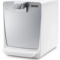
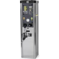
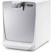
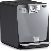
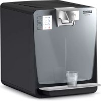
- GENERAL NOTES
- HAZARD LEVELS
- DANGER
- △DANGER
- △WARNING
- CAUTION
- ATTENTION
- SAFETY INSTRUCTIONS
- SYMBOLS ON THE DEVICE
- INTENDED USE
- WARNING
- FORESEEABLE MISUSE
- GENERAL INSTRUCTIONS FOR HANDLING CO2 BOTTLES
- RISK OF EXPLOSION
- DANGER OF DEATH FROM A POSSIBLY BURSTING CO2 GAS CONTAINER
- DANGER OF SUFFOCATION DUE TO ESCAPING CARBON DIOXIDE
- ENVIRONMENTAL PROTECTION
- ACCESSORIES AND SPARE PARTS
- CONSUMABLES
- SCOPE OF DELIVERY
- DESCRIPTION OF THE DEVICE
- FOR THE ILLUSTRATIONS, REFER TO THE GRAPHICS PAGE, ILLUSTRATION A
- INSTALLATION
- CONNECTING THE DEVICE
- CONNECTION DIAGRAM
- ILLUSTRATION B
- CONNECTIONS
- ILLUSTRATION C
- INSERTING THE FILTER
- ILLUSTRATION G
- INITIAL START-UP
- NOTE
- RINSING THE CO₂ MIXING CONTAINER
- RINSING THE DEVICE AND FILTER
- HANDLING THE CO2 BOTTLE
- REMOVING AN EMPTY CO2 BOTTLE
- ILLUSTRATION I
- CONNECT THE NEW CO2 BOTTLE
- HANDLING THE CO2 CYLINDER
- REMOVING AN EMPTY CO2 CYLINDER
- ILLUSTRATION J
- CONNECTING A NEW CO2 CYLINDER
- OPERATION
- FUNCTION
- ILLUSTRATION K
- SHUTTING DOWN
- INITIAL STARTUP AFTER DECOMMISSIONING
- TRANSPORT
- EQUIPMENT SHIPPING
- STORAGE
- CARE AND MAINTENANCE
- REPLACING THE FILTER
- CHEMICAL CLEANING
- ILLUSTRATION P
- ILLUSTRATION Q
- RINSING AFTER CHEMICAL CLEANING
- SAMPLING
- EMPTYING THE DRIP TRAY
- ILLUSTRATION R
- WARRANTY
- CONTENTS
- GENERAL INSTRUCTIONS
- GENERAL INSTRUCTIONS FOR HANDLING CO2 CYLINDERS
- EXPLOSION HAZARD
- DANGER OF SUFFOCATION AS A RESULT OF ESCAPING REFRIGERANT GAS
- ENVIRONMENT
- SPARE PARTS
- FIGURE
- WORKING WITH A CO2 CYLINDER
- REMOVE THE CO2 CYLINDER
- FIGURE J
- FUNCTIONING
- CONTROL
- FIGURE L
- SUSPENSION OF OPERATION
- RESUMING OPERATION AFTER SUSPENSION
- TRANSPORTATION
- NON-COMPLIANCE WITH WEIGHT
- SHIPPING THE DEVICE
- NON-OBSERVANCE OF WEIGHT
- DANGER OF ELECTRIC SHOCK FROM IMPROPER MAINTENANCE OF THE DEVICE
- FIGURE O
- FIGURE P
- RINSE AFTER CHEMICAL CLEANING
- DRIP TRAY
- FIGURE R
- SAFETY STEPS
- SAFETY
- POSSIBLE UNINTENDED USE
- DECLARATION OF COMPONENTS (REACH)
- PPNAT TA 3ANACHI DETANI
- PPOMNBAHHN IICNXIIMIHORO OUHHEHH
- BKA3IEKA
- BIΔIP NPO
- CNOPOXHEHHN IDONA DNN 3BNPAHNKPANELB
- MAJIOHOK R
- TAPAHTRIA
- INFORMATION ON CONSTITUENT SUBSTANCES (REACH)
- ACCESSORIES
- CAP
- FOR DOMESTIC USE
- BOTTLES
- FOR
- CLEANING THE WATER FILTER
- INSTRUCTION
- WORKING WITH THE CO2 CYLINDER
- REPLACING AN EMPTY CO2 CYLINDER
- WORKING WITH CO2 CYLINDERS
- REPLACING A CO2 CYLINDER
- CBPB3BAHE HA HOB CHMHDBP 3A CO
- ФИГРА J
- EKNPNOATAUIA
- ФУНКЦЯ
- MAINTENANCE
- INSTRUCTIONS
- FURRAK
- SHUTDOWN
- START-UP AFTER SHUTDOWN
- TRANSPORT OF THE DEVICE
- RISK OF INJURY
- CHANGING THE FILTER
- HEALTH HAZARD DUE TO BACTERIA
- FIGURE N
- THE RINSING WATER IS WATER FOR CLEANING
- RINSING WITH CHEMICAL CLEANING
- TAKING SAMPLES
- ADJUSTING THE DISPENSING TAP
Brand : Kärcher
Model : WPD 50 Ws
Category : Water dispenser