AWT Fp - Water dispenser Kärcher - Free user manual and instructions
Find the device manual for free AWT Fp Kärcher in PDF.

| Product type | Water dispenser and tire inflator |
| Brand | Kärcher |
| Model | AWT Fp |
| Power supply | 230 V, 50 Hz, 450 W |
| Protection type | IP44 |
| Water supply pressure | 0.1 - 0.5 MPa |
| Compressed air pressure | 0.1 - 0.8 MPa |
| Compressed air flow rate | 100 l/min |
| Dimensions (L x W x H) | 423 x 423 x 1550 mm |
| Weight | 71 kg |
| Temperature range with frost protection | -10 to +40 °C |
| Temperature range without frost protection | +5 to +40 °C |
| Permissible air humidity | 10 - 80 % |
| Sound pressure level (LpA) | < 70 dB(A) |
| Sound power level (LWA) | 76.8 dB(A) |
| Main functions | Non-potable water distribution, tire inflation and deflation |
| Usage | Professional |
| Coin acceptor | Accepts coins: 50 cent EUR, 50 pence GBP, 1 CHF, 1 PLN, 5 NOK |
| Duration setting | 30 s to 7 min via rotary knob |
| Frost protection | Optional (dedicated switch) |
| Daily maintenance | Emptying the coin cassette, checking hoses and nozzle |
| Warranty | According to commercial conditions of the country |
Frequently Asked Questions - AWT Fp Kärcher
User questions about AWT Fp Kärcher
0 question about this device. Answer the ones you know or ask your own.
Ask a new question about this device
Download the instructions for your Water dispenser in PDF format for free! Find your manual AWT Fp - Kärcher and take your electronic device back in hand. On this page are published all the documents necessary for the use of your device. AWT Fp by Kärcher.
USER MANUAL AWT Fp Kärcher
natural_image
Exterior view of a KNOCHER electric vehicle charging station with control panel and fuel injector (no visible text or symbols)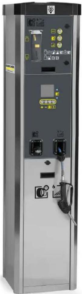
natural_image
Exterior view of a modern electric vehicle charging station with control panel and fuel nozzle (no visible text or symbols)Deutsch 2
English 5
Français 9
Italiano 13
Nederlands 17
Español 21
Português 25
Dansk 29
Norsk 33
Svenska 37
Suomi 40
Ελληνικά 44
Türkçe 48
Русский 52
Magyar 56
Čeština 60
Slovenščina 64
Polski 68
Românește 71
Slovenčina 75
Hrvatski 79
Srpski 83
Български 87
Eesti 91
Latviešu 95
Lietuviškai 98
Українська 102
Inhalt
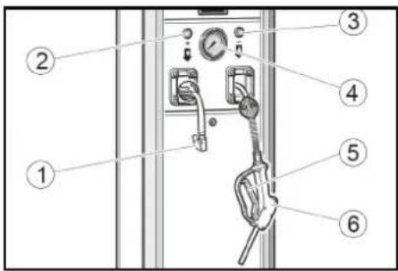
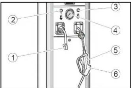
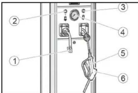
①Taste "STOP"
① Venteilstecker
②Taste +
③Taste -
④Manometer
⑤Hebel
⑥Zapfpistole
Wasser zapfen

①Abdeckung
②Kondensat-Ablassventil
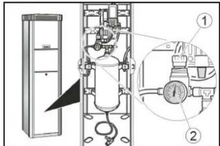
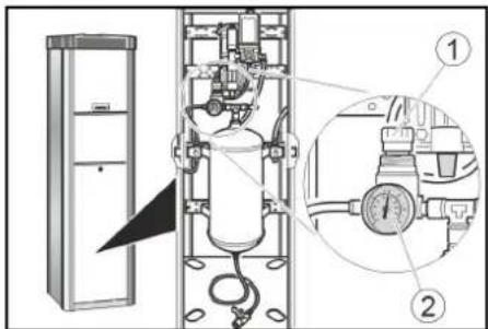
①Druckminderer
②Manometer
12062 Cherasco (Cn) - Italy
Tel. +39 0172 427311
Fax +39 0172 495437
C.F./R.I./P.IVA/V.A.T.: IT 02469390047
Cap. Soc. € 255.000 - REA CN-178422 CCIAA
info@mtmhydro.it
PEC: mtmhydro@multipec.it
www.mtmhydro.it
Cherasco, 2018/09/01
Contents
General notes 5
Environmental protection 5
Accessories and spare parts.... 6
Safety instructions.... 6
Initial startup.... 6
Operation 6
Settings.... 7
Frost protection.... 7
Shutting down 7
Care and service.... 8
Transport.... 8
Storage 8
Troubleshooting guide 8
Warranty 9
Technical data 9
EU Declaration of Conformity 9
General notes
Read these original instructions and the safety instructions chapter before using the
device for the first time. Act in accordance with them.
Keep them safe for future reference or for future owners.
Environmental protection
The packing materials can be recycled. Please dispose of packaging in accordance with the environmental regulations.

Electrical and electronic appliances contain valuable, recyclable materials and often components such as batter-
ies, rechargeable batteries or oil, which - if handled or disposed of incorrectly - can pose a potential threat to human health and the environment. However, these components are required for the correct operation of the appliance. Appliances marked by this symbol are not allowed to be disposed of together with the household rubbish.
Notes on the content materials (REACH)
Current information on content materials can be found at: www.kaercher.com/REACH
Accessories and spare parts
Only use original accessories and original spare parts. They ensure that the appliance will run fault-free and safely. Information on accessories and spare parts can be found at www.kaercher.com.
Safety instructions
Hazard levels
△DANGER
- Indication of an imminent threat of danger that will lead to severe injuries or even death.
⚠ WARNING
- Indication of a potentially dangerous situation that may lead to severe injuries or even death.
△CAUTION
- Indication of a potentially dangerous situation that may lead to minor injuries.
ATTENTION
- Indication of a potentially dangerous situation that may lead to damage to property.
General
To avoid danger to persons, animals and property, it is imperative to read and observe the following documents before operating the device:
- Operating instructions
• All safety instructions - The respectively applicable national regulations
In self-service operation, the operator must ensure that the users are informed by means of clearly visible information notices:
• Potential dangers
- Safety devices
- Operating the device.
Operation
⚠ WARNING
- Children over the age of 8 and persons with reduced physical, sensory or mental capabilities, or those with a lack of experience and knowledge, are only allowed to use the appliance if they are properly supervised, have been instructed with respect to using the appliance safely by a person responsible for their safety, and understand the resultant dangers involved.
• Children must not play with the appliance. - Cleaning and user maintenance may not be carried out by unsupervised children.
- Always keep the area around the device clean and free of oil and grease.
Behaviour in the event of an emergency
- In the event of an emergency, push the STOP button.
①"STOP" button
Symbols on the device

△DANGER
Danger of injury from electrical
voltage.
Do not open any covers that are marked in this way.

⚠ WARNING
Risk of burns from hot surface.
Do not touch any components with this symbol.
Intended use
This device has 2 functions.
- Regulating vehicle tyre pressures by increasing or decreasing pressure.
- Dispensing water that is not suitable as drinking water.
Operation in explosive atmospheres is prohibited.
During operation, the door must be closed and the cover must be attached.
This device is suitable for commercial use.
Calibration requirement
The tyre inflation system of the AWT -C and AWT -C Fp device versions is calibrated and must be checked by the responsible gauging office after installation and then every 2 years.
Initial startup
- Open the on-board water inlet.
- Switch on the on-board power supply.
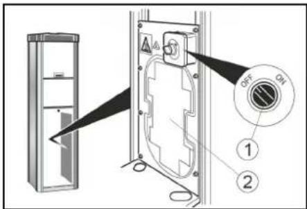
- Open locks.
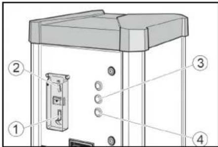
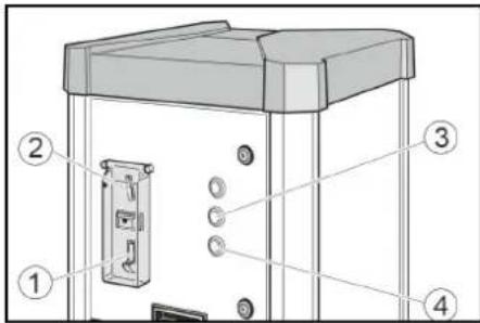
①Main switch
②Door
③Lock
-
Set the main switch to "ON" position. The "STOP" button flashes when the device is in operation.
-
Close the door.
Operation
AWT, AWT Fp operation
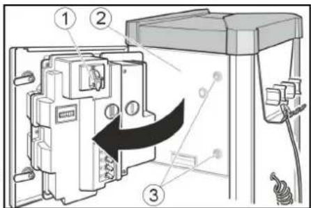
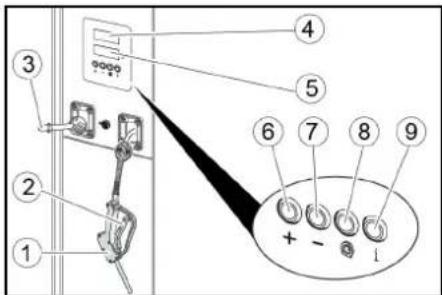
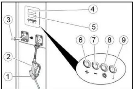
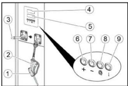
Control elements
① Coin return
②Coin slot
③Tyre pressure button
④Water dispenser button
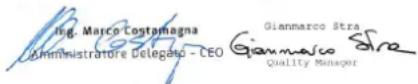
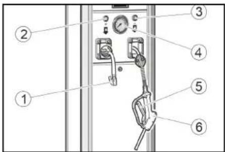
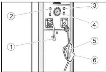
①Valve connector
②Button +
③Button -
④Pressure gauge
⑤ Lever
⑥Fuel pump nozzle
Drawing water


- Insert a coin in the coin slot.
- Press the water dispenser button.
- Hold the fuel pump nozzle in the container opening.
Pull the fuel pump nozzle lever until the desired filling level has been reached.
4. Hang the fuel pump nozzle back on the device.
Checking tyre pressure


- Insert a coin in the coin slot.
- Press the tyre pressure button.
- Secure the valve connector on the tyre valve.
- Read the tyre pressure at the pressure gauge.
- Increase the tyre pressure by pressing the + button or reduce it by pressing the - button.

-
Remove the valve connector.
-
Pull on the hose briefly and feed the hose in via the automatic hose reel.
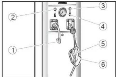
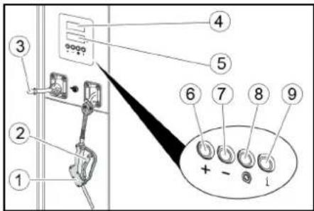
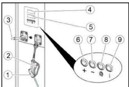
AWT -C, AWT -C Fp operation Control elements
①Coin return
②Coin slot
③Tyre pressure button
④Water dispenser button
①Fuel pump nozzle
② Lever
③Valve connector
④Target pressure display
⑤Tire pressure display
⑥Button +
⑦Button -
⑧Flat tyre button
⑨No function
Drawing water

- Insert a coin in the coin slot.

- Press the water dispenser button.

- Hold the fuel pump nozzle in the container opening. Pull the fuel pump nozzle lever until the desired filling level has been reached.

- Hang the fuel pump nozzle back on the device.

Checking tyre pressure
- Insert a coin in the coin slot.

- Press the tyre pressure button.

- Set the target tyre pressure with the + and - buttons in the target pressure display (upper display).

- Secure the valve connector on the tyre valve. The tyre pressure display (lower display) shows the tyre pressure.

- Wait until an acoustic signal indicates that the tyre target pressure has been reached.

-
Remove the valve connector.
-
Pull on the hose briefly and feed the hose via the automatic hose reel.
Filling flat tyres
If the tyre has no pressure, the device cannot detect that the valve connector has been connected to the valve.

- Insert a coin in the coin slot.

- Press the tyre pressure button.

-
Set the target tyre pressure with the + and - buttons in the target pressure display (upper display).
-
Secure the valve connector on the tyre valve.
The tyre pressure display (lower display) shows the tyre pressure.

- Press the "Flat tyre" button.

- Wait until an acoustic signal indicates that the tyre target pressure has been reached.

-
Remove the valve connector.
-
Pull on the hose briefly and feed the hose via the automatic hose reel.
Settings
Setting the run time
Note
The adjustable run time applies to the insertion of one of the following coins:
• 50 Eurocents
• 50 British pence
• 1 Swiss franc
• 1 Polish złoty
• 5 Norwegian Kroner
Customer Service can set up different types of coins.
- Set the run time with the P I rotary knob. Possible setting range of 30 seconds to 7 minutes.
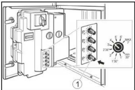
①Rotary knob P I
Note
Rotary knobs P II, P III and P IV have no function.
Frost protection
Device with frost protection
- Turn the frost protection switch "ON" at temperatures below +5°C.
①Frost protection switch
②Frost protection heater
ATTENTION
Risk of damage
The frost protection is active only when the main switch is "ON".
When activating the frost protection, check whether the main switch is in the "ON" position.
Note
The frost protection heater is not thermostat-controlled. When switched on, the heater is continuously in use.
Device without frost protection
In a device without frost protection, a shut-down must be carried out if there is risk of frost.
Shutting down
- Close the water inlet
- Drain the condensate in the compressed air tank (see "Maintenance tasks").
- Set the main switch to the "OFF" position.
Shutdown in the case of potential frost
- Close the water inlet.
- Remove water from the device and supply line.
- Drain the condensate from the compressed air tank (see "Maintenance work").
- Set the main switch in "OFF" position.
Care and service
Daily
- Empty the coin cassette (see "Maintenance tasks").
- Check the general condition of the device.
- Check the condition of the valve connector.
- Check the condition of the hose lines.
- Open the lower cover and check the condition of the compressor.
- Have damaged parts replaced.
Weekly
- Clean the outside of the device.
- Drain the condensate in the compressed air tank (see "Maintenance tasks").
ATTENTION
Risk of damage
The water in the compressed air line can damage the tyre pressure sensor. Drain the condensate in the compressed air tank regularly.
Service very 2 years
Only with AWT -C, AWT -C Fp
- Have the pressure measuring device of the tyre inflator calibrated by the gauging office.
Maintenance work
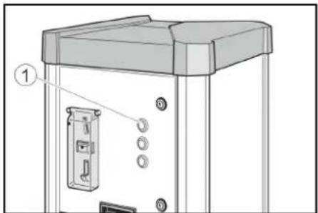
Emptying the coin cassette
- Open the door.
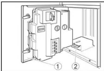
①Door
②Coin cassette
2. Remove and empty the coin cassette.
Drain the condensate
- Remove the cover.
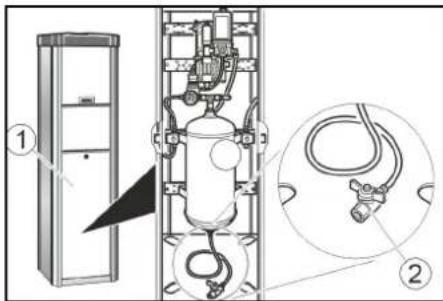
①Bar cover
②Condensate drain valve
- Hold the condensate drain valve over a shaft or collecting container.
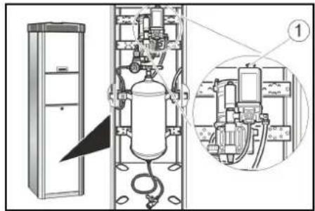
⚠ WARNING
Risk of injury, risk of damage
The water stream escaping from the condensate drain valve can cause injury or damage.
Never point the condensate drain valve at people, animals, the device or electrical components.
-
Slowly open the condensate drain valve and drain the condensate.
-
Close the condensate drain valve.
-
Attach the cover.
Transport
△CAUTION
Risk of injury, risk of damage
Be aware of the weight of the device during transportation.
- When transporting in vehicles, secure the device against slipping and tipping over according to the applicable guidelines.
Storage
△CAUTION
Risk of injury and damage
Be aware of the weight of the device during storage.
Troubleshooting guide
△DANGER
Danger from electric shock.
Before working on the device, set the main switch to "OFF" and disconnect the on-board power supply.
The device does not work
- Check the on-site voltage supply.
- Set the main switch to "ON" position.
- Contact customer service.
The device does not start after the valve connector has been connected to the tyre.
- Check that the valve connector is seated correctly.
- Check the condition of the hose and of the valve connector.
- Press the "tyre flat" button.
There is no compressed air
● Pull the compressor on-button upward.
① Compressor on-button
● The compressor is overheated: Wait until the compressor has cooled off.
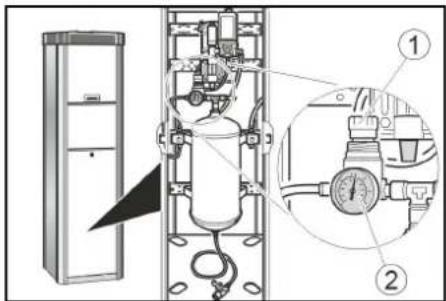
The tyre pressure is too low
- Check the pressure on the pressure gauge. Readjust the pressure reducer if necessary.
①Pressure reducer
②Pressure gauge
Malfunctions with information shown on the display
| Fault Cause Rectification | ||
| ER1 Unstable pressure measurement due to defective valve connector or hose | Replace the valve connector.Replace the hose. | |
| ER2, ER7 The tyre pressure is too low.Unstable pressure measurement due to defective valve connector or hose. | Check the tyre pressure on the pressure gauge and readjust the pressure reducer if necessary.Replace the valve connector.Replace the hose. | |
| ER3 | The tyre pressure is too low. | Check the pressure on the pressure gauge and readjust the pressure reducer if necessary. |
| ER4 | The tyre pressure is too high. | Check the pressure on the pressure gauge and readjust the pressure reducer if necessary. |
| ER5 | The voltage supply is disturbed. | Contact customer service. |
| ER6, ER8, ER9, ERU, ERB | Malfunction in the electronics. | Contact customer service. |
| ERP | The valve connector came loose during inflation.The tyre pressure is not stable. | Check that the valve connector is seated correctly.Check the pressure on the pressure gauge and readjust the pressure reducer if necessary. |
Warranty
The warranty conditions issued by our relevant sales company apply in all countries. We shall remedy possible malfunctions on your appliance within the warranty period free of cost, provided that a material or manufacturing defect is the cause. In a warranty case, please contact your dealer (with the purchase receipt) or the next authorised customer service site. (See overleaf for the address)
Technical data
Electrical connection
| Mains voltage V 230 |
| Phase ~ 1 |
| Frequency Hz 50 |
| Power rating W 450 |
| Degree of protection IP44 |
Compressed air
| Flow rate | l/min | 100 |
| Pressure | MPa | 0,1...0,8 |
Water connection
| Feed pressure | MPa | 0,1...0,5 |
Ambient conditions
| Temperature with frost protection | °C | -10...+40 |
| Temperature without frost protection | °C | +5...+40 |
| Humidity | % | 10...80 |
Noise emission
| Sound pressure level LpA | dB(A) | <70 |
| Sound power level LWA + K uncertaintyWA | dB(A) | 76,8 |
| Sound power level LWA + uncertainty KWA | dB(A) | 4 |
Dimensions and weights
| Weight | kg | 71 |
| Length | mm | 423 |
| Width | mm | 423 |
| Height AWT | mm | 1550 |
| Height AWT-C | mm | 1760 |
Subject to technical modifications.
EU Declaration of Conformity
We hereby declare that the machine described below complies with the relevant basic safety and health requirements in the EU Directives, both in its basic design and construction as well as in the version placed in circulation by us. This declaration is invalidated by any changes made to the machine that are not approved by us.
Product: Tyre inflator
Type: AWT, AWT Fp, AWT -C, AWT -C Fp
Currently applicable EU Directives
2006/42/EC
2014/35/EU
2014/30/EU
Documentation supervisor: Gianmarco Stra
MTM Hydro Srl
Via Moglia, 33
12062 Cherasco (Cn) - Italy
Tel. +39 0172 427311
Fax +39 0172 495437
CF / RI / P.IVA / VAT: IT 02469390047
Cap. Soc. €255,000 - REA CN-178422
CCIAA
info@mtmhydro.it
PEC: mtmhydro@multipec.it
www.mtmhydro.it
Cherasco, 2018/09/01
Contenu
①Touche « STOP »
①Cache
12062 Cherasco (Cn) - Italy
Tel. +39 0172 427311
Fax +39 0172 495437
C.F./R.I./P.IVA/V.A.T.°: IT 02469390047
Cap. Soc. € 255.000 - REA CN-178422 CCIAA
info@mtmhydro.it
PEC°: mtmhydro@multipec.it
www.mtmhydro.it
Cherasco, 2018/09/01
Indice
www.kaercher.com/REACH
Accessori e ricambi
①Tasto "STOP"
①Copertura
①Toets "STOP"
①Hoofdschakelaar
②Deur
③Slot
①Munt-teruggave
②Muntinworp
③Toets Bandenspanning
④Toets waterafgifte
①Ventielstekker
②Toets +
③Toets -
④Manometer
⑤Hendel
⑥Tappistool
Water onttrekken

①Munt-teruggave
②Muntinworp
③Toets Bandenspanning
④Toets waterafgifte
①Deur
②Muntcassette
①Afdekking
②Condensaataftapkraan
①Inschakeltoets compressor
①Drukregelaar
②Manometer
①Tecla «STOP»
①Interruptor principal
②Puerta
③Cerrojo
① Cubierta
①Teda "STOP"
①Interruptor principal
②Porta
③Fechadura
①Conector de válvula
②Tecla +
③Tecla -
④Manómetro
⑤Alavanca
⑥Pistola distribuidora
Tirar água


①Porta
②Cassete de moedas
①Cobertura
②Válvula de drenagem de condensado
12062 Cherasco (Cn) - Italy
Tel. +39 0172 427311
Fax +39 0172 495437
C.F./R.I./P.IVA/V.A.T.: IT 02469390047
Cap. Soc. 255 000 € - REA CN-178422
CCIAA
info@mtmhydro.it
PEC: mtmhydro@multipec.it
www.mtmhydro.it
Cherasco, 01/09/2018
Indhold
①Tasten "STOP"
Symboler på maskinen

⚠️FARE
①Møntretur
②Møntindkast
③Knap dæktryk
④Knap vandaftapning
①Ventilstik
②Knap +
③Knap
④Manometer
⑤Arm
⑥Päfyldningspistol
Aftapning af vand


①Møntretur
②Møntindkast
③Knap dæktryk
④Knap vandaftapning
①Afdækning
①Tilkoblingsknap kompressor
①«STOP»-tast
①Myntretur
②Myntinnkast
③Dekktrykk-tast
④Vannutslipp-tast
①Ventilmunnstykke
②+ tast
③- tast
④Manometer
⑤Spak
⑥Tappekran
Tapp vann
- Legg en mynt i myntinnkastet.


- Trykk på vanntasten.

①Myntretur
②Myntinnkast
③Dekktrykk-tast
④Vannutslipp-tast
①Dør
②Myntkassett
2. Trekk ut myntkassetten og tøm den.
Tøm kondensvann
①Deksel
①Trykkforminsker
②Manometer
①Knapp "STOP"
Symboler på maskinen

⚠️FARA
①Ventilkoppling
②Knapp +
③Knapp -
④Manometer
⑤Spak
⑥Vattenpistol
Tappa vatten

①Knapp Frostskydd
①Dörr
②Myntkassett
①Kåpa
①Tillkopplingsknapp kompressor
①"STOP"-painike
①Ovi
②Kolikkokasetti
①Suojus
①Paineenalennin
②Painemittari
①Πλήκτρο "STOP"
①Κάλυμμα
①Ρυθμιστής πίεσης
②Μανόμετρο
12062 Cherasco (Cn) - Italy
Tel. +39 0172 427311
Fax +39 0172 495437
C.F./R.I./P.IVA/V.A.T.: IT 02469390047
Cap. Soc. € 255.000 - REA CN-178422
CCIAA
info@mtmhydro.it
PEC: mtmhydro@multipec.it
www.mtmhydro.it
Cherasco, 2018/09/01
İçindekiler
Genel uyarılar 48
Çevre koruma 48
Aksesuarlar ve yedek parçalar.... 48
①"STOP" düğmesi
Cihazdaki simgeler

TEHLIKE
①Antifriz şalteri
② Antifriz isiticisi
DIKKAT
①Kapi
①Kapak
Tip: AWT, AWT Fp, AWT -C, AWT -C Fp
①Кнопка «STOP»
①Редуктор
②Манометр
12062 Cherasco (Cn) - Italy
0Тел.: +39 0172 427311
①"STOP" gomb
①Fökapcsoló
② Ajtó
③Zár
①Burkolat
①Nyomáscsökkentő
②Manométer
www.kaercher.com/REACH
①Klávesa „STOP“
①Dvířka
②Kazeta na mince
①Kryt
①Tipka STOP
Simboli na napravi

⚠NEVARNOST
①Glavno stikalo
②Vrata
③Ključavnica
-
Glavno stikalo postavite v položaj ON. Ko naprava deluje, tipka STOP utripa.
-
Zaprite vrata.
Upravljanje
Upravljanje AWT, AWT Fp Upravljalni elementi

① Vračanje kovancev
②Reža za kovance
③Tipka za tlak v pnevmatikah
① Ventilni vtič
②Tipka +
③Tipka -
④Manometer
⑤Ročica
⑥Točilna pištola
Točenje vode


natural_image
Technical diagram of a gas cylinder system with internal components and a magnified inset showing internal wiring (no text or labels)①Vklopni gumb kompresorja
- Kompresor je pregret: Počakajte, da se kompresor ohladi.
Zračni tlak je prenizek
- Preverite tlak na manometru. Po potrebi prilagodite reduktor tlaka.
①Reduktor tlaka
②Manometer
Motnje s prikazom na zaslonu
| Napaka Vzrok Odpravljanje | ||
| ER1 Nestabilno merjenje tlaka zaradi poškodo-vanega ventilnega vtiča ali gibke cevi | Zamenjajte ventilni vtič.Zamenjajte gibko cev. | |
| ER2, ER7 | Zračni tlak je prenizek.Nestabilno merjenje tlaka zaradi poškodo-vanega ventilnega vtiča ali gibke cevi. | Preverite zračni tlak na manometru, po potrebi pona-stavite reducirni ventil.Zamenjajte ventilni vtič.Zamenjajte gibko cev. |
| ER3 | Zračni tlak je prenizek. | Preverite tlak na manometru, po potrebi ponastavite re-ducirni ventil. |
| ER4 | Zračni tlak je previsok. | Preverite tlak na manometru, po potrebi ponastavite re-ducirni ventil. |
| ER5 | Oskrba z napetostjo je motena. | Obvestite servisno službo. |
| ER6, ER8, ER9, ERU, ERB | Motnje v elektroniki. | Obvestite servisno službo. |
| ERP | Med napihovanjem se je ventilni vtič sprostil.Zračni tlak ni stabilen. | Preverite pravilno nasedanje ventilnega vtiča.Preverite tlak na manometru, po potrebi ponastavite re-ducirni ventil. |
Garancija
①Przycisk „STOP”
① Wyłącznik główny
②Drzwi
③Zamek
①Drzwi
② Kaseta na monety
①Ostona
①Butonul „STOP“
Simboluri pe aparat

△PERICOL
①Uşă
②Casetă de monede
①Capac
①Buton de pornire compresor
①Reductor de presiune
②Manometru
Tip: AWT, AWT Fp, AWT -C, AWT -C Fp
Directive UE relevante
2006/42/CE
2014/35/UE
2014/30/UE

①Tlačidlo "STOP"
① Spínač ochrany proti mrazu
②Ohrievanie na ochranu proti mrazu
POZOR
①Dvierka
②Kazeta na mince
①Kryt
① Tlačidlo na zapínanie kompresora
①Redukčný ventil
②Manometer
Poruchy s indikáciou na displeji
12062 Cherasco (Cn) - Italy
Tel. +39 0172 427311
Fax +39 0172 495437
C.F./R.I./P.IVA/V.A.T.: IT 02469390047
Cap. Soc. 255 000 € - REA CN-178422
CCIAA
info@mtmhydro.it
PEC: mtmhydro@multipec.it
www.mtmhydro.it
Cherasco, 01.09.2018
Sadržaj
Opće napomene 79
Zaštita okoliša 79
Pribor i zamjenski dijelovi.... 79
Sigurnosni napuci 79
Puštanje u pogon.... 80
Rukovanje 80
Postavke 81
Zaštita od smrzavanja.... 81
Stavljanje izvan pogona 81
①Tipka „STOP“
Simboli na uređaju

△OPASNOST
Opasnost od električnog napona.
①Glavna sklopka
②Vrata
③Brava
4. Postavite glavnu sklopku u položaj „ON”. Tipka „STOP“ treperi dok uređaj radi.
5. Zatvorite vrata.
Rukovanje
Rukovanje verzijama uređaja AWT, AWT Fp
①Povrat kovanica
②Otvor za ubacivanje kovanica
③Tipka za tlak u gumi
④Tipka za predaju vode
①Utikač ventila
②Tipka +
③Tipka -
④Manometar
⑤Poluga
⑥ Pištolj za točenje
Točenje vode
- Ubacite kovanicu u otvor za ubacivanje kovanica.
- Pritisnite tipku za predaju vode.
- Pištolj za točenje držite u otvoru spremnika.
①Povrat kovanica
②Otvor za ubacivanje kovanica
③Tipka za tlak u gumi
④Tipka za predaju vode
①Pištolj za točenje
②Poluga
③Utikač ventila
④Zaslon za zadani tlak
⑤Zaslon za tlak u gumi
⑥Tipka +
⑦Tipka -
⑧Tipka za praznu gumu
⑨bez funkcije
Točenje vode

- Ubacite kovanicu u otvor za ubacivanje kovanica.

- Pritisnite tipku za predaju vode.

- Pištolj za točenje držite u otvoru spremnika.
①Sklopka zaštite od smrzavanja
②Grijanje za zaštitu od smrzavanja
PAŽNJA
①Vrata
② Kaseta za kovanice
- Izvucite kasetu za kovanice i ispraznite je.
①Poklopac
① Gumb za uključivanje kompresora
- Kompresor je pregrijan: Pričekajte da se kompresor ohladi.
Tlak zraka je prenizak
①Reduktor tlaka
②Manometar
Smetnje s prikazom na zaslonu
①Taster „STOP“
Simboli na uređaju

△OPASNOST
①Glavni prekidač
②Vrata
③Brava
4. Glavni prekidač postavite u položaj „STOP“.
„STOP“ treperi kada je uređaj u pogonu.
5. Zatvorite vrata.
Rukovanje
Rukovanje AWT, AWT Fp Komandni elementi
① Vraćanje novčića
②Ubacivanje kovanica
③Taster za pritisak u gumi
④Taster za predaju vode
①Utikač ventila
②Taster +
③Taster -
④Manometar
⑤Poluga
⑥Pištolj za točenje
Točenje vode


① Vraćanje novčića
②Ubacivanje kovanica
③Taster za pritisak u gumi
④Taster za predaju vode
①Pištolj za točenje
②Poluga
③Utikač ventila
④Displej zadatog pritiska
⑤Displej pritiska u gumi
⑥Taster +
⑦Taster -
⑧Taster za praznu gumu
⑨nema funkcije
Točenje vode


① Prekidač za zaštitu od smrzavanja
②Grejanje zaštite od smrzavanja
PAŽNJA
①Vrata
② Kaseta za kovanice
2. Izvucite kasetu za novčiće i ispraznite je.
①Poklopac
②Ventil za ispuštanje kondenzata
2. Ventil za ispuštanje kondenzata držite iznad šahta ili prihvatne posude.
⚠UPOZORENJE
Opasnost od povrede, opasnost od oštećenja
Mlaz vode koji izlazi preko ventil za ispuštanje kondenzata može da uzrokuje povrede ili oštećenja.
Ventil za ispuštanje kondenzata nikada nemojte usmeravati na ljude, životinje, uređaj ili električne komponente.
- Polako otvorite ventil za ispuštanje kondenzata i ispustite kondenzat.
- Zatvorite ventil za ispuštanje kondenzata.
- Postavite poklopac.
Transport
△OPREZ
Opasnost od povrede, opasnost od oštećenja
Prilikom transporta obratite pažnju na težinu uređaja.
- Prilikom transporta u vozilima uređaj osigurajte od isklizavanja i prevrtanja prema dotično važećim direktivama.
Skladištenje
△OPREZ
Opasnost od povreda i oštećenja
① Taster za uključivanje kompresora
- Kompresor je pregrejan: Sačekajte da se kompresor ohladi.
Pritisak vazduha je suviše nizak
● Proverite pritisak na manometru. Po potrebi, podesite reduktor pritiska.
①Reduktor pritiska
②Manometar
Smetnja sa prikazom na displeju
| Greška Uzrok Otklanjanje | ||
| ER1 Neprecizno merenje pritiska | zbogneispravnog utikača ventila ili creva | Zamenite utikač ventila.Zamenite crevo. |
| ER2, ER7 Pritisak vazduha je suviše nizak. | Neprecizno merenje pritiska usledneispravnog utikača ventila ili creva. | Proverite pritisak vazduha na manometru, po potrebi naknadno podesite reduktor pritiska.Zamenite utikač ventila.Zamenite crevo. |
| ER3 | Pritisak vazduha je suviše nizak. | Proverite pritisak na manometru, po potrebi naknadno podesite reduktor pritiska. |
| ER4 | Pritisak vazduha je suviše visok. | Proverite pritisak na manometru, po potrebi naknadno podesite reduktor pritiska. |
| ER5 | Postoji smetnja u napajanju. | Obavestite servisnu službu. |
| ER6, ER8, ER9, ERU, ERB | Smetnja na elektronici. | Obavestite servisnu službu. |
| ERP | Utikač ventila se otpustio prilikom upumpavanja.Pritisak vazduha nije stabilan. | Proverite da li je utikač ventila pravilno postavljen.Proverite pritisak na manometru, po potrebi naknadno podesite reduktor pritiska. |
Garancija
U svakoj zemlji važe uslovi garancije koje je izdala naša nadležna distributivna organizacija. Bilo kakve smetnje na uređaju otklanjamo besplatno u garantnom roku, ukoliko je uzrok smetnje greška u materijalu ili proizvodnji. U slučaju koji podleže garanciji obratite se sa računom vašem distributeru ili narednoj ovlašćenoj lokaciji servisne službe. (Adresu vidi na poleđini)
Tehnički podaci
| Električni priključak | ||
| Napon električne mreže | V | 230 |
| Faza | ~ | 1 |
| Frekvencija | Hz | 50 |
| Priključna snaga | W | 450 |
| Vrsta zaštite | IP44 | |
| komprimovanog vazduha | ||
| Protočna količina | l/min | 100 |
| Pritisak | MPa | 0,1...0,8 |
| Priključak za vodu | ||
| Dovodni pritisak | MPa | 0,1...0,5 |
| Uslovi okruženja | ||
| Temperatura sa zaštitom od smrzavanja | °C | -10...+40 |
| Temperatura bez zaštite od smrzavanja | °C | +5...+40 |
| Vlažnost vazduha | % | 10...80 |
| Emisija buke | ||
| Nivo zvučnog pritiska LpA | dB(A) | <70 |
| Nivo zvučne snage LWA + nepouzdanost KWA | dB(A) | 76,8 |
| Nivo zvučne snage LWA + nepouzdanost KWA | dB(A) | 4 |
Dimenzije i težine
| Težina | kg | 71 |
| Dužina | mm | 423 |
| Širina | mm | 423 |
| Visina AWT | mm | 1550 |
| Visina AWT-C | mm | 1760 |
Zadržano pravo na tehničke promene.
①Бутон "STOP"
Символи върху уреда

⚠️ ОПАСНОСТ
Опасност поради
① Главен прекъсвач
②Врата
③Ключалка
①Капак
12062 Cherasco (Cn) - Italy
①Nupp „STOP“
①Pealüliti
②Uks
③Lukk
①Ventiili otsak
②Nupp +
③Nupp -
④Manomeeter
⑤Hoob
⑥Püstol
Vee laskmine
- Laske münt mündiavasse.


①Püstol
②Hoob
③Ventiili otsak
④Sihtrõhu kuva
⑤Rehvirōhu kuva
⑥Nupp +
⑦Nupp -
⑧Tühja rehvi nupp
⑨ilma funktsioonita
Vee laskmine


①Uks
②Mündisachtel
①Kompressori sisselülitamise nupp
①Röhureduktor
②Manomeeter
①Taustiņš "STOP"
Simboli uz ierīces

ABISTAMI
①Vārsta spraudnis
②Taustinš +
③Taustinš -
④Manometrs
⑤Svira
⑥Padeves pistole
Üdens nemšana

①Padeves pistole
②Svira
③Vārsta spraudnis
④Nepieciešamā spiediena displejs
⑤Riepu spiediena displejā
①Durvis
②Monētu kasete
①Pārsegs
① Spiediena reduktors
②Manometrs
①Mygtukas „STOP“
①Pagrindinis jungiklis
②Durelès
③Sklastis
①Ventilio kištukas
②Mygtukas „+“
③Mygtukas "
④Manometras
⑤Svirtis
⑥Pildymo pistoletas
Vandens pripylimas

① Gaubtas
① Kompresoriaus jungimo mygtukas
①Slėgio ribotuvas
②Manometras
①Кнопка «STOP»
Символи на пристрої

△НЕБЕЗПЕКА
①Кришка
①Редуктор тиску
②Манометр
natural_image
Black and white icon of a hand giving a thumbs-up gesture (no text or symbols)THANK YOU!
MERCI! DANKE! iGRACIAS!

Register your product and benefit from many advantages.
www.kaercher.com/welcome


Rate your product and tell us your opinion.
natural_image
Icon showing a gear and wrench inside a square frame (no text or symbols)www.kaercher.com/dealersearch
Alfred Kärcher SE & Co. KG
Alfred-Kärcher-Str. 28-40
71364 Winnenden (Germany)
Tel.: +49 7195 14-0
Fax: +49 7195 14-2212