HD 18504 Cage Adv - Pressure washer Kärcher - Free user manual and instructions
Find the device manual for free HD 18504 Cage Adv Kärcher in PDF.
Download the instructions for your Pressure washer in PDF format for free! Find your manual HD 18504 Cage Adv - Kärcher and take your electronic device back in hand. On this page are published all the documents necessary for the use of your device. HD 18504 Cage Adv by Kärcher.
USER MANUAL HD 18504 Cage Adv Kärcher
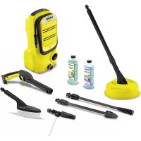
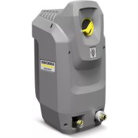
Register your product www.kaercher.com/welcome HD 18/50-4 Cage Classic HD 18/50-4 Cage Advanced
dB(A) 101 Ausnahmegrund nach Verordnung (EU) 2019/1781 Anhang I Abschnitt 2 (12): j) 13DE– 1 Please read and comply with these original instructions prior to the initial operation of your appliance and store them for later use or subsequent own- ers. – Before initial start-up it is definitely nec- essary to read the safety information no. 5.963-314.0! – In case of transport damage inform ven- dor immediately. – When unpacking the product, make sure that no accessories are missing and that none of the package contents have been damaged. Notes about the ingredients (REACH) You will find current information about the ingredients at: www.kaercher.com/REACH Illustrations on Page 2 1 Push handle 2 Hose holder 3 Hose/cable holder 4 High pressure hose 5 Operating hour counter 6 Water connection 7Filter 8Filter casing 9 Parking brake 10 Classic: Overflow valve Advanced: Overflow valve with pres- sure relief 11 Manometer 12 Oil level indicator 13 High pressure connection 14 Oil drain screw 15 Thermostat valve 16 Actuation lever for parking brake 17 Power cable with plug (60 Hz model without plug) 18 Power switch 19 Lock 20 Indicator lamp low water 21 Control lamp operating state 22 Motor protection switch 23 Storage for spray pipe 24 Water shortage safeguard 25 Safety valve 26 High pressure connection 27 Oil filling nozzle 28 Accessory compartment 29 Transport eyelets 30 Strut for crane loading 31 Power nozzle with covering nut 32 Spray lance 33 Trigger gun 34 Lever for hand spray gun 35 Safety catch Contents Environmental protection ... EN 1 Overview... EN 1 Proper use ... EN 2 Symbols on the machine... EN 2 Safety instructions... EN 2 Safety Devices ... EN 3 Start up ... EN 3 Operation ... EN 5 Transport... EN 7 Storing the device ... EN 7 Care and maintenance ... EN 7 Troubleshooting ... EN 8 Warranty ... EN 9 General information ... EN 9 EU Declaration of Conformity . EN 10 Declaration of Conformity ... EN 10 Technical specifications ... EN 11 Environmental protection The packaging material can be recycled. Please do not throw the packaging material into household waste; please send it for recycling. Old appliances contain valuable materials that can be recycled; these should be sent for recy- cling. Batteries, oil, and similar substances must not enter the environment. Please dispose of your old appliances using appro- priate collection systems. Please do not release engine oil, fuel oil, diesel and petrol into the environment Pro- tect the ground and dispose of used oil in an environmentally-clean manner. Overview 14 EN– 2 – The operating elements for the cleaning process are yellow. – The controls for the maintenance and service are light gray. Use this high pressure cleaner exclusively for: – Cleaning machines, vehicles, buildings, tools. – with accessories and spare parts ap- proved by Kärcher. 몇 WARNING Observe regulations of water supplier. According to applicable regula- tions, the appliance must never be used on the drinking water net without a system separator. A suit- able system separator by KÄRCHER or al- ternatively a system separator according to EN 12729 type BA must be used. Water that was flowing through a system separator is considered non-drinkable. 몇 CAUTION Always connect the system separator to the water supply, never directly to the appli- ance! DANGER Pointer to immediate danger, which leads to severe injuries or death. 몇 WARNING Pointer to a possibly dangerous situation, which can lead to severe injuries or death. 몇 CAUTION Pointer to a possibly dangerous situation, which can lead to minor injuries. ATTENTION Pointer to a possibly dangerous situation, which can lead to property damage. DANGER Risk of injury! – Only use original high-pressure hoses. – The high-pressure hose and the injec- tion system must be suitable for the maximum operating pressure given in the Technical Data. – Avoid contact with chemicals. – Check the high pressure hose daily. Do not use hoses with kinks. Stop using the high pressure hose if the external wire layer is visible. – Do not use the high-pressure hose any- more if the winding is damaged. – Lay the high-pressure hoses in such a way that no vehicle can drive over it. Colour coding Proper use Symbols on the machine High pressure jets can be dangerous if improperly used. The jet must not be directed at persons, ani- mals, live electrical equipment or at the appli- ance itself. Risk of damage from freezing water! During winter, store the device in a heated room or empty it. Danger of hearing dam- age. Always wear suita- ble hearing protection when working with the device. Risk of injury! Wear safe- ty goggles. Risk of burns on account of hot surfaces! Beware of dangerous electrical current! Safety instructions Hazard levels High pressure hose 15EN– 3 – Do not use high-pressure hoses that have been driven over, kinked, pressed or bent even if there is no externally vis- ible damage. – Store the high-pressure hoses in such a way that they are not subject to any me- chanical load. – Maximum tightening torque of the screwed connections of the high-pres- sure hose; 20 Nm. Safety devices serve to protect the user and must not be rendered in operational or their functions bypassed. The switch prevents unintented starting of the appliance. Stop the appliance during breaks or after operation. The safety catch on the handgun prevents the handgun from being released uninten- tionally. – only for Classic variant – If the hand spray gun is closed, the overflow valve opens and the entire wa- ter volume will flow back to the pump suction side. Overflow valve is set and sealed by the man- ufacturer. Setting only by customer service. – only for Advanced variant – If the hand spray gun is closed, the overflow valve opens and the entire wa- ter volume will flow back to the pump suction side. – If the trigger gun is closed, the water pressure in the high-pressure hose is reduced. This reduces the actuating force of the trigger gun and increases the service life of the device. Overflow valve is set and sealed by the manufacturer. Setting only by customer service. The safety valve opens when the overflow valve is defective. The safety valve is set by the manufacturer and sealed. Setting only by customer ser- vice. The lack of water fuse shuts off the engine when the water supply is scarce (water pressure too low). The indicator lamp "lack of water" will illumi- nate. The thermostat valve protects the high- pressure pump from unacceptable heating during circuit operation when the trigger gun is closed. The thermostat valve opens when the per- missible water temperature of 80°C is ex- ceeded and lets out the hot water into the open. The motor protection switch interrupts the electric circuit if the motor is overloaded. DANGER Risk of injury! Device, supply lines, high- pressure hose and connections must be in faultless condition. If they are not in a per- fect condition then the device must not be used. Replace the transport screw with the supplied bleed screw. Check oil level of the high pressure pump. The oil level must be at the centre of the oil level display. Add oil if required (see technical speci- fications). Safety Devices Power switch Safety catch Overflow valve Overflow valve with pressure relief Safety valve Water shortage safeguard Thermostat valve Motor protection switch Start up Check oil level 16 EN– 4 몇 WARNING Risk of injury due to unsuitable accesso- ries. Only use accessories that are ap- proved for the working pressure of the de- vice (see "Technical Data"). Only install accessories while the device is switched off. Maximum tightening torque of the screwed con- nections of the high-pressure hose; 20 Nm. Connect high pressure hose and spray pipe to the hand spray gun. Mount the power nozzle on the spray pipe. Tighten covering nut firmly. Connect the high pressure hose to the high pressure connection point of the machine. – For connection values refer to technical specifications. – The electrical connections must be done by an electrician according to IEC 60364-1. 몇 WARNING The highest allowed net impedance at the electrical connection point (refer to techni- cal data) is not to be exceeded. In case of any uncertainty regarding the present net impedance at your connection point, please contact your local power sup- ply company. DANGER – Check whether the voltage data on the type plate corresponds with the voltage of the power source. – Unsuitable electrical extension cables can be dangerous. Only use approved and appropriately marked electrical ex- tension cables with a sufficient line cross section when outdoors:
With this appliance model, the matching mains plug must be installed onto the mains connecting line by an electrician. 몇 WARNING Observe regulations of water supplier. According to applicable regula- tions, the appliance must never be used on the drinking water net without a system separator. A suit- able system separator by KÄRCHER or al- ternatively a system separator according to EN 12729 type BA must be used. Water that was flowing through a system separator is considered non-drinkable. 몇 CAUTION Always connect the system separator to the water supply, never directly to the appli- ance! For connection values refer to technical specifications. Connect the supply hose (minimum length 7.5 m, minimum diameter 1“) to the water connection point of the appli- ance (such as the tap). The supply hose is not included. Open the water supply. ATTENTION Dirty water Premature wear and tear or deposits in the device. Supply the device using only clean water, or recycled water that does not exceed the specified limit values. The following limit values apply to the water supply: – Upstream water filter: ≤10 µm – Solid body content: maximum 50 mg/l – Total hardness: 3-15° dH, 30-150 mg/l CaO, 54-268 mg/l CaCO
: <100 mg/l Shut off water supply. Unscrew the filter casing. Pull out and clean the filter. Vent appliance. Note: The device is supplied with an 80 μm filter. A 50 μm filter (6.414-063.0) should be used when the rotor nozzle is used. A prepressure pump must be connected in front of the appliance to suction water. Fill the suction hose with water. Advance pressure pump: 2.637-017.0 DANGER Never suck in water from a drinking water container. DANGER Never draw in fluids containing solvents or undiluted acids and solvents! This includes petrol, paint thinner and heating oil. The spray mist is highly inflammable, explosive and poisonous. Do not use acetone, undi- luted acids and solvents, as they corrode the materials used on the appliance. Remove air from appliance before oper- ation. Open the water supply. Unscrew the nozzle. Press the lever on the hand spray gun. Switch on the appliance and let it run until the water exiting from the spray pipe is bubble-free. Switch off the appliance and fit the noz- zle again. DANGER – The appliance may not be operated in explosive atmospheres. – Place the appliance on firm, even sur- face. – The high-pressure cleaner must not be used by children. (Risk of accidents on account of improper use of the device). – The water jet coming out of the high- pressure nozzle causes the gun to re- coil. Further, an angular spray pipe can cause additional torque. Hence, hold the spray lance and gun firmly. – Never direct the water jet on to persons, animals, the appliance itself or electrical components. Never direct the water jet on to persons, animals, the appliance itself or electrical components. – Risk of injury from high-pressure jet and unsettled dirt. Wear safety goggles, protective gloves, protective overalls and special safety boots with foot pro- tection. – The jet must not be directed by the user at him/herself or at other persons to clean clothing or footwear. – Do not use the device other persons are within reach of it. – Danger of hearing damage. Always wear suitable hearing protection when working with the device. – Wheels/tyre valves must not be cleaned with this device due to the high water pressure. – Do not clean materials containing as- bestos or other health-hazardous sub- stances. – Pay attention to ensure that all screws of all connecting hoses are tightened properly. – The lever of the trigger gun must not be clamped tight during operation.
Do not drive over the main cable or the high pressure hose. – Only work with sufficient lighting. Cleaning the filter Suck in water from vessel Deaerating the appliance Operation 18 EN– 6 Open the water supply. Plug in the mains plug. Set the appliance switch to "I". Unlock the safety lock at the hand- spray gun by pressing it. Press the lever on the hand spray gun. 몇 WARNING The water jet that is emitted from the high- pressure nozzle results in a repulsion pow- er acting on the hand spray gun. Make sure that you have a firm footing and hold the trigger gun and the spray lance with both hands. The shoulder support (2.639-251.0) should be used to prevent injuries and to make work easier at recoil pressures > 150 N. The appliance is equipped with the follow- ing nozzles: – Power nozzle, 15° spray angle High pressure flat stream (15°) for large areas of contamination. The working pressure can be read from the manometer. Note: Always direct the high-pressure jet at the object to be cleaned from a distance to avoid damage from high pressure. Release the lever of the trigger gun. Use the safety catch to secure the handgun lever. Store the hand spray gun and spray pipe in the accessory mount. The working pressure can be changed by using different high-pressure nozzles. Select a nozzle from the table above. Unscrew the union nut from the spray lance. Replace nozzle. Screw on and tighten the union nut. Note: This method of pressure adjustment al- ways means that the full flow rate of 1800 l/ h is always available. Release the lever of the trigger gun. Set the appliance switch to "0". Shut off water supply. Activate hand spray gun until device is pressure less. Use the safety catch to secure the handgun lever. Remove the water inlet hose from the appliance. Pull out the mains plug. Stow away the mains cable, the high- pressure hose and accessory at the ap- pliance. Turning on the Appliance High pressure operation Power nozzle Interrupting operation Changing working pressure Pressure MPa (bar) Nozzle size Order number Flat jet nozzles 50 (500) 15060 5.765-263.0 35 (350) 15075 2.113-073.0 25 (250) 15095 2.113-075.0 15 (150) 15120 2.113-077.0 Detail nozzles 50 (500) 060 5.765-264.0 35 (350) 075 2.113-074.0 25 (250) 095 2.113-076.0 15 (150) 120 2.113-078.0 Finish operation 19EN– 7 몇 WARNING Risk of damage! Freezing water in the ap- pliance can destroy parts of the appliance. Store the appliance in a heated room dur- ing winter or empty it. During longer breaks in operation, it is advisable to pump in anti- frost agents into the appliance. Screw off water supply hose and high pressure hose. Blow through machine with com- pressed air. Note: Observe handling instructions of the anti- freeze agent manufacturer. Pump in conventional frost protection agents through the appliance. A certain corrosion protection is achieved with this as well. 몇 CAUTION Risk of personal injury or damage! Mind the weight of the appliance during transport. Pull the actuation lever of the parking brake all the way to the back. Press the actuation lever of the parking brake completely to the front. Connect the lifting device in the center of the strut to load by crane. DANGER Risk of injury due to machine dropping. – Adhere to the local accident prevention guidelines and safety notes. – Check the appliance for crane loading for damage prior to each transport by crane. – Check the lifting unit for damage prior to each transport by crane. – Only lift up the appliance by this mech- anism when loading by crane. – Do not use stop chains. – Protect the lifting device from inadvert- ent load release. – Remove the spray pipe with hand spray gun as well as loose articles prior to transporting by crane. – Do not transport any articles on the ap- pliance during the lifting process. – The appliance must only be transported by properly trained crane personnel. – Do not stand below the load. – Ensure that no persons are present in the immediate vicinity of the crane. – Do not leave the appliance on the crane unattended. Check all screws of the appliance for tightness; retighten if necessary. During forklift transport, secure the device against falling using the transport eyelets according to the applicable guidelines. When transporting in vehicles, secure the device against slipping and tipping over ac- cording to the applicable guidelines. 몇 CAUTION Risk of personal injury or damage! Consid- er the weight of the appliance when storing it. This appliance must only be stored in inte- rior rooms. DANGER Risk of injury! Always switch off the appli- ance and pull out the mains plug before care and maintenance work. Frost protection Drain water Flush device with anti-freeze agent Transport Driving Stopping Transport by crane Safety information about cranes Safety check Forklift transport When transporting in vehicles Storing the device Care and maintenance 20 EN– 8 You can sign with your dealer a contract for regular safety inspection or even sign a maintenance contract. Please take advice on this matter. Check mains cable. The mains cable should not have been damaged (risk of electrical shock). A damaged mains cable must be re- placed immediately by an authorised Customer Service Engineer or an elec- trician. Check the high pressure hose for dam- ages (risk of bursting). Please arrange for the immediate ex- change of a damaged high-pressure hose. Check oil level from the oil level display of the high pressure pump. Please contact Customer Service im- mediately if the oil is milky (water in oil). Check appliance (pump) for leaks. 3 drops per minute are permitted and can come out from the lower side of the appliance. Call Customer Service if there is heavy leakage. Clean the filter inlay. Change the oil in the high pressure pump. Change the oil in the high pressure pump. For oil type refer to technical specifica- tions. Turn out the oil drain screw. Drain the oil in a collection basin. Screw in oil drain plug. Fill in new oil slowly until the centre of the oil level display. Note: Air pockets must be able to leak out. You can rectify minor faults yourself with the help of the following overview. If in doubt, please consult the authorized customer service. DANGER Risk of injury! Always switch off the appli- ance and pull out the mains plug before care and maintenance work. WARNING Repair work and work on the electrical components may only be performed by an authorised customer service. The indicator lamps display the operating states (green) and interruptions (red). Reset: Set the appliance switch to "0". Wait for a while. Set the appliance switch to "I". Continuous green: – The appliance is now ready for operation. Continuous red light: – Water shortage – No power Check whether the voltage indicated on the type plate corresponds to the volt- age of the socket. Check the mains connection cable for damages. – The water shortage safeguard was trig- gered due to low water inlet pressure. The indicator lamp "lack of water" will il- luminate. Check water inlet pressure, minimum value see "Specifications". Turn the device switch to "0" and turn on again to restart the system. – Motor overloaded/overheated or the motor circuit breaker has tripped. Switch off appliance and let it cool down. Remove the cause of the prob- lem. Turn on the appliance again. Maintenance Safety inspection/ maintenance contract Before each use Weekly After the first 50 operating hours Yearly or after 500 operating hours Troubleshooting Indicator lamp Operating status display Fault indication Appliance is not running 21EN– 9 – Wrong nozzle Check nozzle for correct size (see tech- nical specifications). – Flushed the nozzle. Clean/ replace nozzle. – Filter is dirty. Clean filter at the water connection. Unscrew the filter casing, remove the filter, clean it and replace it. – Air within the system Appliance ventilation: Unscrew the nozzle. Switch on the ap- pliance and let it run until the water ex- iting from the spray pipe is bubble-free. Switch off the appliance and fit the noz- zle again. – Pipe inlets to pump are leaky or blocked Check all supply lines to the pump for leaks or blockages. 3 drops per minute are permitted and can come out from the lower side of the appliance. Call Customer Service if there is heavy leakage. Check all supply lines to the high-pres- sure pump for leaks or blockages. Appliance ventilation: Unscrew the nozzle. Switch on the ap- pliance and let it run until the water ex- iting from the spray pipe is bubble-free. Switch off the appliance and fit the noz- zle again. The warranty terms published by our com- petent sales company are applicable in each country. We will repair potential fail- ures of the appliance within the warranty period free of charge, provided that such failure is caused by faulty material or de- fects in fabrication. The warranty comes only into effect if your vender fills out the supplied reply card com- pletely at purchase, stamps and signs and you send it to the local distribution company of your country. In the event of a warranty claim please con- tact your dealer or the nearest authorized Customer Service centre. Please submit the appliance, including all accessories, and the proof of purchase. 몇 WARNING Risk of injury due to unsuitable accesso- ries. Only use accessories that are ap- proved for the working pressure of the de- vice (see "Technical Data"). – Only use accessories and spare parts which have been approved by the man- ufacturer. The exclusive use of original accessories and original spare parts ensures that the appliance can be oper- ated safely and trouble free. – At the end of the operating instructions you will find a selected list of spare parts that are often required. – For additional information about spare parts, please go to the Service section at www.kaercher.com. Device is not building up pressure High pressure side is leaky High pressure pump is vibrating Warranty General information Accessories and Spare Parts 22 EN– 10 We hereby declare that the machine described below complies with the relevant basic safety and health requirements of the EU Directives, both in its basic design and construction as well as in the version put into circulation by us. This declaration shall cease to be valid if the ma- chine is modified without our prior approval. The signatories act on behalf of and with of the authority of the company management. Documentation supervisor: S. Reiser Alfred Kärcher SE & Co. KG Alfred-Kärcher-Straße 28-40 71364 Winnenden (Germany) Tel.: +49 7195 14-0 Fax: +49 7195 14-2212 Winnenden, 2021/05/01 We hereby declare that the product de- scribed below complies with the relevant provisions of the following UK Regulations, both in its basic design and construction as well as in the version put into circulation by us. This declaration shall cease to be valid if the product is modified without our prior approval. The signatories act on behalf of and with of the authority of the company management. Documentation supervisor: S. Reiser Alfred Kärcher SE & Co. KG Alfred-Kärcher-Straße 28-40 71364 Winnenden (Germany) Tel.: +49 7195 14-0 Fax: +49 7195 14-2212 Winnenden, 2021/05/01 EU Declaration of Conformity Product: High pressure cleaner Type: 1.367-xxx Relevant EU Directives 2006/42/EG (+2009/127/EG) 2014/30/EU 2000/14/EG 2011/65/EU 2009/125/EG Harmonised directive(s) (EU) 2019/1781 Applied harmonized standards EN 55014–1: 2017 + A11: 2020 EN 55014–2: 2015 EN 61000–3–2: 2014 EN 61000–3–11: 2000 EN 62233: 2008 EN 1829-1 EN 1829 -2 EN IEC 63000: 2018 Applied conformity evaluation method 2000/14/EC 2000/14/EC: Appendix V Sound power level dB(A) HD 18/50-4 Cage Measured: 98 Guaranteed: 100 Chairman of the Board of Management Director Regulatory Affairs & Certification Declaration of Conformity Product: High pressure cleaner Type: 1.367-xxx Currently applicable UK Regulations S.I. 2008/1597 (as amended) S.I. 2016/1091 (as amended) S.I. 2001/1701 (as amended) S.I. 2012/3032 (as amended) S.I. 2010/2617 (as amended) Commission Regulations (EU) 2019/1781 Applied designated standards EN 55014–1: 2017 + A11: 2020 EN 55014–2: 2015 EN 61000–3–2: 2014 EN 61000–3–11: 2000 EN 62233: 2008 EN 1829-1 EN 1829 -2 EN IEC 63000: 2018 Applied conformity assessment proce-dure S.I. 2001/1701 (as amended): Schedule 8 Sound power level dB(A) HD 18/50-4 Cage Measured: 98 Guaranteed: 100 Chairman of the Board of Management Director Regulatory Affairs & Certification 23EN– 11 Technical specifications Type HD 18/50-4 Cage Clas- sic EU 1.367-160.0 HD 18/50-4 Cage Clas- sic KAP 1.367-161.0 HD 18/50-4 Cage Ad- vanced 1.367-162.0 Power connection Voltage V 380 - 415 380 - 440 380 - 415 Current type Hz 50 60 50 Connected load kW 36 Mains fuse (slow-blow) A 63 Type of protection IPX5 Maximum allowed net impedance Ohm 0,22 Water connection Max. feed pressure MPa (bar) 1 (10) Inflow pressure (min.) with max. water volume MPa (bar) 0,05 (0,5) Max. feed temperature °C 60 Min. feed volume l/h (l/min) 2000 (33,3) Inlet hose length (min.) m 7,5 Inlet hose diameter (min.) Inch 1 Performance data Working pressure MPa (bar) 50 (500) Max. excess operating pressure (safety valve) MPa (bar) 62 (620) Water flow rate l/h (l/min) 1800 (30) Nozzle size -- 15060 Recoil force of the trigger gun N 158 Fuel Oil quantity - pump l 2,5 Oil type - pump SAE 15W-40 Dimensions and weights Length x width x height mm 747 x 1317 x 1093 Typical operating weight kg 317 Values determined as per EN 60335-2-79 Hand-arm vibration value Rotary nozzle m/s
: < 50 mg/l – Krzemiany, Si