
G 3650 - Paper cutter OLYMPIA - Free user manual and instructions
Find the device manual for free G 3650 OLYMPIA in PDF.
| Product type | Lever-action paper cutter |
| Brand | OLYMPIA |
| Model | G 3650 |
| Cutting capacity | 50 sheets (80 g/m²) |
| Maximum cutting thickness | 5 mm |
| Cutting length | 360 mm |
| Minimum cut | 35 mm |
| Dimensions (L × W × H) | 503 × 508 × 459 mm |
| Weight | 6.6 kg |
| Support surface | 280 × 360 mm |
| Power supply | 1 LR6 (AA) battery |
| Laser positioning | Yes, with switch |
| Supported materials | Paper, cardboard |
| Automatic support fixation | Yes |
| Safety | Arm lock, lever lock, safety cover |
| Maintenance | Soft, dry cloth, no chemicals |
| Blade adjustment | Fine adjustment screw with hex key |
| Included spare parts | Spare blade, hex key, assembly aids in compartment |
| Warranty | Return to store with original packaging and receipt |
Frequently Asked Questions - G 3650 OLYMPIA
User questions about G 3650 OLYMPIA
0 question about this device. Answer the ones you know or ask your own.
Ask a new question about this device
Download the instructions for your Paper cutter in PDF format for free! Find your manual G 3650 - OLYMPIA and take your electronic device back in hand. On this page are published all the documents necessary for the use of your device. G 3650 by OLYMPIA.
USER MANUAL G 3650 OLYMPIA
GB Operating Instructions
HR Priručnik s uputama
FR Mode d'emploi
natural_image
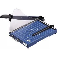
White manual paper cutting machine with metal handle and grid pattern (no visible text or symbols)Hebelschneider / Lever Cutter / Cisailles à levier / Taglierina a leva / Cortador de palanca / Cortador de alavanca / Dźwignia tnqca / Válcová řezačka / Rezač s polugom / Hefboomsnijder / Kóφτης με μοχλό / Kollu kesici / قعفرالعطاق

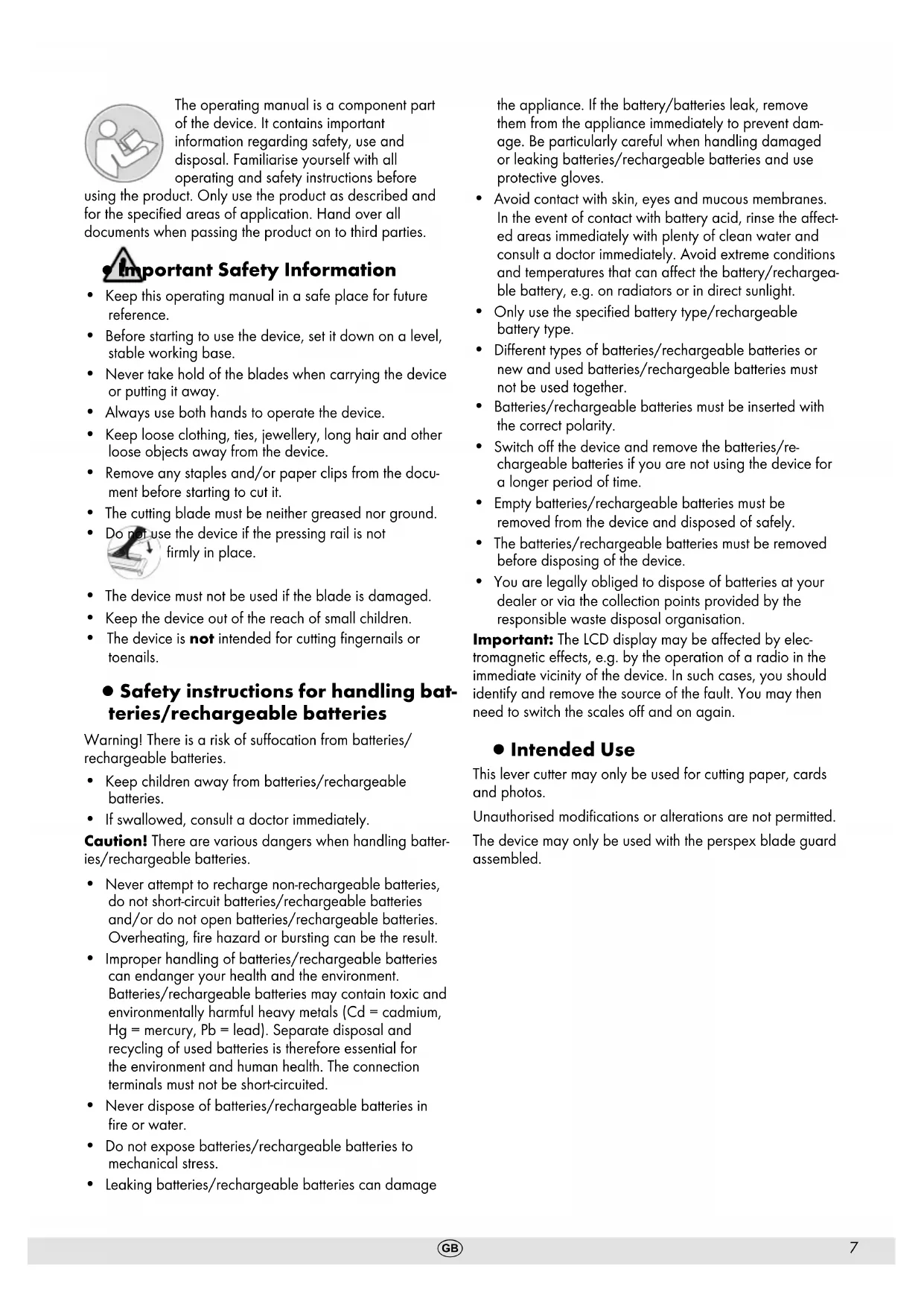
The operating manual is a component part of the device. It contains important information regarding safety, use and disposal. Familiarise yourself with all operating and safety instructions before
using the product. Only use the product as described and for the specified areas of application. Hand over all documents when passing the product on to third parties.

Important Safety Information
- Keep this operating manual in a safe place for future reference.
- Before starting to use the device, set it down on a level, stable working base.
- Never take hold of the blades when carrying the device or putting it away.
• Always use both hands to operate the device. - Keep loose clothing, ties, jewellery, long hair and other loose objects away from the device.
- Remove any staples and/or paper clips from the document before starting to cut it.
- The cutting blade must be neither greased nor ground.
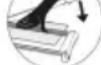
- Do not use the device if the pressing rail is not
firmly in place.
- The device must not be used if the blade is damaged.
- Keep the device out of the reach of small children.
- The device is not intended for cutting fingernails or toenails.
● Safety instructions for handling batteries/rechargeable batteries
Warning! There is a risk of suffocation from batteries/rechargeable batteries.
- Keep children away from batteries/rechargeable batteries.
• If swallowed, consult a doctor immediately.
Caution! There are various dangers when handling batteries/rechargeable batteries.
- Never attempt to recharge non-rechargeable batteries, do not short-circuit batteries/rechargeable batteries and/or do not open batteries/rechargeable batteries. Overheating, fire hazard or bursting can be the result.
- Improper handling of batteries/rechargeable batteries can endanger your health and the environment. Batteries/rechargeable batteries may contain toxic and environmentally harmful heavy metals (Cd = cadmium, Hg = mercury, Pb = lead). Separate disposal and recycling of used batteries is therefore essential for the environment and human health. The connection terminals must not be short-circuited.
- Never dispose of batteries/rechargeable batteries in fire or water.
- Do not expose batteries/rechargeable batteries to mechanical stress.
• Leaking batteries/rechargeable batteries can damage
the appliance. If the battery/batteries leak, remove them from the appliance immediately to prevent damage. Be particularly careful when handling damaged or leaking batteries/rechargeable batteries and use protective gloves.
- Avoid contact with skin, eyes and mucous membranes. In the event of contact with battery acid, rinse the affected areas immediately with plenty of clean water and consult a doctor immediately. Avoid extreme conditions and temperatures that can affect the battery/rechargeable battery, e.g. on radiators or in direct sunlight.
- Only use the specified battery type/rechargeable battery type.
- Different types of batteries/rechargeable batteries or new and used batteries/rechargeable batteries must not be used together.
- Batteries/rechargeable batteries must be inserted with the correct polarity.
- Switch off the device and remove the batteries/rechargeable batteries if you are not using the device for a longer period of time.
- Empty batteries/rechargeable batteries must be removed from the device and disposed of safely.
- The batteries/rechargeable batteries must be removed before disposing of the device.
- You are legally obliged to dispose of batteries at your dealer or via the collection points provided by the responsible waste disposal organisation.
Important: The LCD display may be affected by electromagnetic effects, e.g. by the operation of a radio in the immediate vicinity of the device. In such cases, you should identify and remove the source of the fault. You may then need to switch the scales off and on again.
- Intended Use
This lever cutter may only be used for cutting paper, cards and photos.
Unauthorised modifications or alterations are not permitted. The device may only be used with the perspex blade guard assembled.
• Non-intended use use
Only cut materials complying with the specifications in Section Technical Data.
Any use other than that described in Intended use is considered improper use.
- Insert battery (LR6)
Attention: Important technical information before first use!
Remove the insulating tape from the battery compartment.
Carry out the following steps to insert the batteries.
-
Remove the battery compartment cover.
-
Insert a battery in the pole direction.
- Replace the battery compartment cover.
Note: The battery compartment is located on the underside of the device. Markings in the battery compartment help ensure the batteries are inserted with correct polarity.
- Remove battery (LR6)
Carry out the following steps to remove the batteries.
- Remove the battery compartment cover.
- Remove the batteries.
- Replace the battery compartment cover.
• Overview of Operating Elements
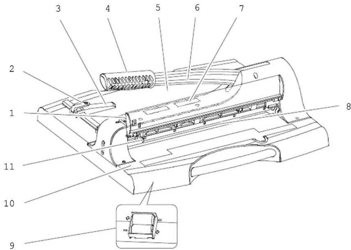
- Guillotine arm lock (upper mechanism)
- Paper guide lock
- Paper guide
- Handle of guillotine arm
- Positioning lines and measuring systems
- Guillotine arm
- Viewing window
- Blade
- Battery compartment
- Laser positioning switch
- Locking the cutting lever (lower position)
- Guillotine
- Remove the device carefully from the packaging.

Attention: Risk of injury! The guillotine blade is very sharp! Never reach in towards the guillotine blade or take hold of it.
- Before starting to use the device, set it down on a level, stable working base.
Note: The cutting lever (6) is equipped with a
The cutting board is secured to the underside of the cutting board with a strap.
-
Remove the strap from the guillotine arm (6).
-
Use the handle (4) to move the guillotine arm (6) upwards.
Note: For safety reasons, the cutting lever is locked in the upper position.
- Fold the safety cover (13) upwards until it engages in the locking mechanism of the cutting lever (1).
- Place the material to be cut in the required position.
Note: Use the paper guide (3) and the grid and measuring devices (5) to position the material to be cut precisely. - Press the locking mechanism of the cutting lever (1) slightly upwards and fold the safety cover (13) downwards.
- Cut the material by drawing the guillotine arm lock (1) towards you and pressing the guillotine arm (6) downwards using the handle (4).

Attention: Risk of injury! The guillotine blade is very sharp! Never reach in towards the guillotine blade or take hold of it.
Note: Secure the cutting lever (6) with the lock (11) after use.
- Use the handle (4) and press the guillotine arm (6) downwards.
- Press the lock (11) inwards. The guillotine arm is then locked in its bottom position.
Note: To unlock the cutting lever, press it down slightly. The lock (11) releases and the cutting lever (6) can be moved upwards again.
Note: If the cutting pattern of the blade is not clean, the position of the blade can be adjusted or the blade can be replaced, see section Adjusting the blade or replacing the blade.
- Laser Positioning
The laser positioning feature provided helps you to ensure the material to be cut is positioned accurately. The laser indicates the exact cutting edge by means of a red line. You can look through the viewing window (7) to see the position at which the material will be cut.
-
Press the switch (10). The laser is switched on.
-
Press the switch (10) again. The laser is switched off.
Note: For a longer battery life, switch off the laser positioning when you are not using the device.
- Paper guide
- Release the lock (2) for the paper guide (3).
Note: Do not attempt to move the paper guide (3) if the lock (2) has not been released.
- Position the paper guide (3) with the aid of the positioning lines and measuring systems (5).
Note: The paper guide (3) can be infinitely adjusted in the rail.
-
Lock the paper guide (3). The paper guide (3) now serves as a stopper for the material to be cut.
-
Assembling the Blade Protection
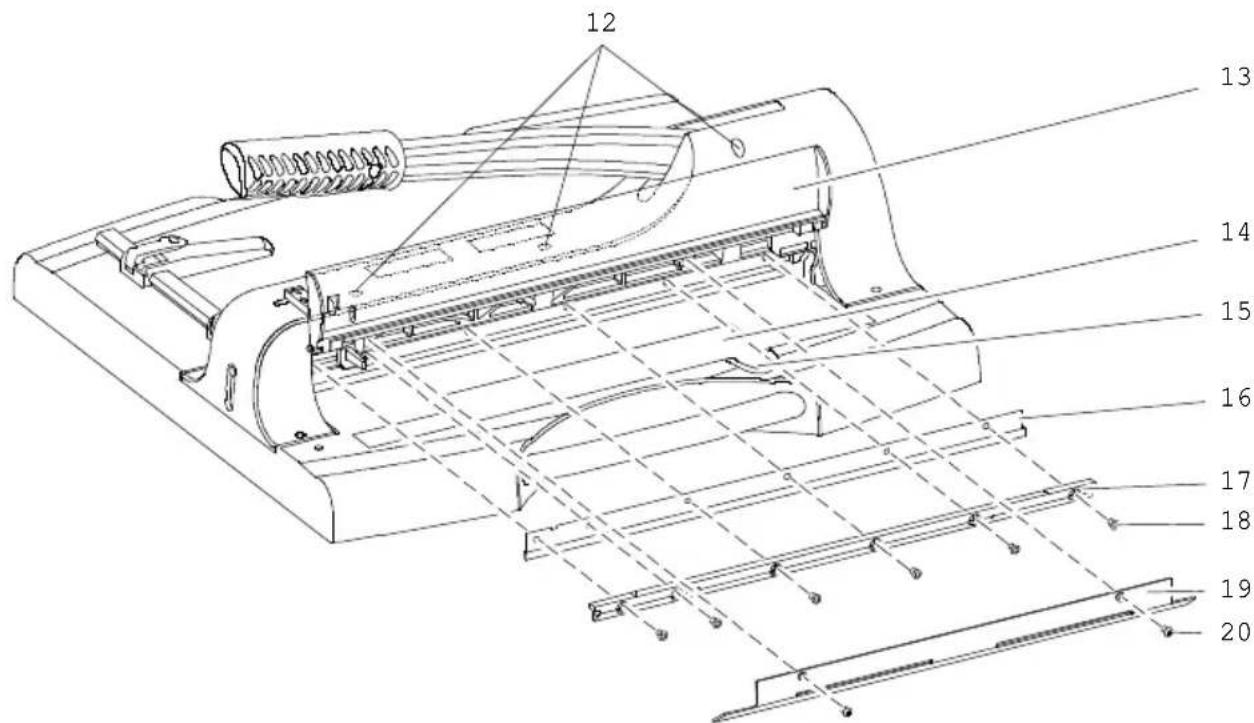
- Blade adjustment screws
- Safety guard
- Spare part and tool compartment
- Screw for spare part and tool compartment
-
Blade
-
Fastening rail
- Screws for fastening rail
- Blade guard
- Screws for blade guard
- Changing the Blade
Note: Before changing the blade, follow the instructions in the Adjusting the blade section.
A spare blade and tools with which to change the blade are available in the spare part and tool compartment (14).
- Loosen the screw securing the spare part and tool compartment (15).
- Remove the tools (hex key, assembling aid), spare blade with cut protection and separate cut protection for the old blade.
-
Release the lock (1) and move the guillotine arm (1) downwards using the handle (4).
-
Press the lock (11) inwards.
-
Open the safety guard (13).
-
Loosen the screws (20) in the blade guard (19) and remove it.
-
Loosen the screws 2 and 5 (counting from the left) of the six screws in the fastening rail (18) and assemble the assembling aid in the free screw holes.
-
Loosen the other screws in the fastening rail (18).
-
Use the assembling aid to carefully remove the fastening rail (17) and blade (16).

Attention: Risk of injury! The guillotine blade is very sharp! Never reach in towards the guillotine blade or take hold of it.
- Carefully assemble the cut protection taken from the spare part and tool compartment (14) on the old blade (16). Remove the old blade (16) from the fastening rail (17) and install the new blade properly aligned (pay attention to the holes) on the fastening rail (17).
- Remove the cut protection carefully from the new blade (16).
- Assemble the assembling aid in the screw holes 2 and 5 (counting from the left) in the fastening rail (17) and install it back in the device.
-
Insert the screws (18) of the mounting rail (17) into the free screw holes one after the other and tighten them carefully.
-
Remove the mounting aids and insert the remaining screws (18) of the mounting rail (17) into the screw holes.
- Tighten all the screws (18) for the fastening rail (17) evenly.
- Replace the blade guard (19) back on the device and tighten the screws (20) in the blade guard firmly.
- Place the tools and cut protection in the spare part and tool compartment (14) and tighten the screw securing the spare part and tool compartment (15).
- Adjusting the Blade
If the cut produced by the blade is not clean, you can adjust the position of the blade.
- Move the guillotine arm to its bottom position. Pull the locking mechanism of the cutting lever (1) towards you and press the cutting lever (6) on the handle (4) downwards. Press the lock (11) inwards. The guillotine arm is then locked in its bottom position.
- Open the spare parts and tool compartment (14) by loosening and removing the screw (15).
- Remove the Allen key from the spare parts and tool compartment (14).
- First insert the Allen key into the rear hole of the screws (12). The insertion aid indicates that the hex key must be inserted angled at about 15 degrees to the right. Insert the hex key in the other screws (12) in the same was in order to reach the respective screw with the hex key.
- Turn the blade adjustment screws (12) clockwise in the areas where the cut is not clean. Take the utmost care when making the adjustment. Test the quality of the cut during the process.
- Place the tool in the spare parts and tool compartment (14) and tighten the screw of the spare parts and tool compartment (15).
Note: Before replacing a blade, the blade adjustment screws (12) must be turned back to their original position. The blade adjustment screws (12) must be unscrewed (anticlockwise) sufficiently far that the threads of the blade adjustment screws (12) are no longer visible beyond the fastening rail (17).
- Cleaning

Attention: Risk of injury! The trimmer blade is very sharp! Take the utmost care when cleaning the trimmer blade!
Clean the housing surfaces with a soft, dry, lint-free cloth. Do not use any solvents or cleaning agents.
- Technical Data
Material for cutting Paper, cardboard
Cutting capacity 50 sheets (80 g / m²)
Maximum thickness 5 mm
Cutting length 360 mm
Minimum cut 35 mm
Dimensions 503 × 508 × 459 mm
Base for paper 280 × 360 mm
Weight 6.6 kg
Automatic fixation of the material when cutting.
- Disposal

Find out about the options for taking back old appliances and used batteries free of charge from your retailer.

Packaging materials must be disposed of according to local regulations.
The packaging is made from environmentally friendly materials that can be disposed of at local recycling centres. Ask your local authority about the options for correct disposal.
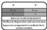
Observe the labelling of the packaging material when separating waste; these are marked with abbreviations (b) and numbers (a) with the following meaning: 1-7: Plastics / 20-22: Paper and cardboard / 80-98: Composite materials.
The adjacent symbol means that old electrical and electronic appliances must be disposed of separately from household waste in accordance with legal regulations. Dispose of your appliance at the collection point of your municipal waste disposal organisation.
Defective or used batteries must be recycled in accordance with Directive 2006/66/EC and its amendments. Return batteries and/or the device to the collection facilities provided.

The CE Mark on the device confirms conformity.
The Declaration of Conformity can be read online at www.go-europe.com.

The Triman logo is only valid for France.
The logo is only valid for Italy.
The logo is only valid for Spain.
- Warranty
Dear customer,
We are delighted that you have chosen this equipment. In the case of a defect, please return the device together with the receipt and original packing material to the point of sale
- Manufacturer
-
Zavarivanje rezačkog ključa (gornja pozicija)
-
Zavaravanje papira
-
Vodič za papir
-
Drška za podizanje noža
-
Rastere i mjerne jedinice
-
Rezač za kosu
-
Prozor za pregled
-
Škarinska letva
-
Komora za baterije
-
Prekidač za lasersku pozicioniranje
-
Zavarivanje rezačkog ključa (donja pozicija)
- Rezač s polugom
- Pazljivo izvadite uređaj iz pakiranja.

Upozorenje: opasnost od ozljeda! Nož preklopnog rezača je vrlo oštar! Nikad ne dirajte nož preklopnog rezača.
- Postavite uređaj na ravnu i stabilnu radnu površinu prije upotrebe.
Napomena: Klizna osovina (6) je pričvršćena za donju stranu rezne ploče trakom.
-
Razdvojite sigurnosnu sponu za transport s kliješta za rezanje (6).
-
Premaknite rezački kotačić (6) na dršku (4) prema gore.
- Vrste za podešavanje noževa
- Zaprta zaštita
- Sekcija za rezervne dijelove i alate
- Vrč za rezervne dijelove i alate
- Škarice
- Pritrjeveni nosač
- Vrste vijaka pričvrsne letvice
- Poklopac noža
- Vrste noževa poklopca
- Messer wechseln
Napomena: Prije nego što promijenite nož, pogledajte uputu u odjeljku Podešavanje noža.
U odjeljku za rezervne dijelove i alate (14) nalazi se rezervno oštrilo s alatom za zamjenu oštrice.
-
Odvrnite vijak pretinca za rezervne dijelove i alate (15).
-
Uzmite alat (ključ s unutarnjom šestokutnom glavom, pomoćni alat za montažu), zamjenski nož s zaštitom od rezanja i zasebnu zaštitu od rezanja za stari nož.
- Otpustite zaključavanje (1) i pomaknite reznički kotačić na dršku (4) prema dolje.
- Pritisnite na zaključavanje (11).
- Otvorite sigurnosnu zaštitu (13).
- Odvrnite vijci (20) za poklopac noža (19) i uklonite poklopac.
- Najprije odvrnite vijci 2 i 5 (brojeni odozdo) od ukupno 6 vijaka pričvrsne letvice (18) i umetnite montažne pomagala u slobodne rupe za vijak.
- Otopite ostale vijci pričvrsne letvice (18)..
- Pomoću montažnih pomagala pažljivo izvadite pričvrsni nosač (17) i nož (16).

Upozorenje: opasnost od ozljeda! Nož preklopnog rezača je vrlo oštar! Nikad ne dirajte nož preklopnog rezača.
- Pazljivo stavite zaštitu od rezanja iz pretinca za rezervne dijelove i alate (14) na staro noževo oštrilo (16). Uzmite staro noževo oštrilo (16) s nosača (17) i postavite novo noževo oštrilo na nosač (17) točno prema položaju (pogledajte rupe!).
- Pazljivo odvrnite zaštitu od rezanja s novog noža (16).
- Uvucite montažne pomagala u rupe za vijak 2 i 5 (brojeno odozdo) pričvrsne letvice (17) i ponovno ih pričvrstite na uređaj.
- Poredom umetnite vijci (18) pričvrsne letvice (17) u slobodne rupe za vijce i nježno ih čvrsto zakvačite.
- Uklonite montažne pomagala i umetnite preostale vijke (18) pričvrsne letvice (17) u rupe za vijke.
- Sve vijke (18) pričvornog nosača (17) ravnomjerno čvrsto zakrenite.
- Postavite poklopac za noževe (19) na uređaj i čvrsto zakrenite vijci poklopca za noževe (20).
- Postavite alat i zaštitu od rezanja u pretinac za rezervne dijelove i alate (14) i čvrsto zakrenite vijak pretinca za rezervne dijelove i alate (15).
• Nastavitak noža
The image is too blurry to recognize any text content.
وال Clubs phenomena Bohyan.


- Important Safety Information
- ● Safety instructions for handling batteries/rechargeable batteries
- - Intended Use
- • Non-intended use use
- - Insert battery (LR6)
- - Remove battery (LR6)
- • Overview of Operating Elements
- - Guillotine
- - Laser Positioning
- - Paper guide
- - Changing the Blade
- - Adjusting the Blade
- - Cleaning
- - Technical Data
- - Disposal
- - Warranty
- - Manufacturer
- - Rezač s polugom
- - Messer wechseln
- • Nastavitak noža
Brand : OLYMPIA
Model : G 3650
Category : Paper cutter