
Vario Duplex 4000 - Paper cutter OLYMPIA - Free user manual and instructions
Find the device manual for free Vario Duplex 4000 OLYMPIA in PDF.


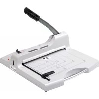
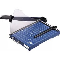
| Product type | Guillotine paper cutter |
| Model | Vario Duplex 4000 |
| Brand | Olympia |
| Cutting capacity (sheets) | Up to 40 sheets (80 g/m²) |
| Maximum cutting width | 400 mm |
| Maximum cutting length | 400 mm |
| Dimensions (W × D × H) | 620 × 480 × 240 mm |
| Weight | 12.5 kg |
| Operation | Manual (lever) |
| Main functions | Straight cut, duplex cut (two sides simultaneously), adjustable stop |
| Maintenance and cleaning | Clean the blade with a soft dry cloth; lubricate the blade periodically |
| Safety | Transparent blade guard, lever safety lock |
| Spare parts and repairability | Replacement blade available, Olympia after-sales service |
| General information | Office or workshop use; suitable for paper, light cardboard |
Frequently Asked Questions - Vario Duplex 4000 OLYMPIA
User questions about Vario Duplex 4000 OLYMPIA
0 question about this device. Answer the ones you know or ask your own.
Ask a new question about this device
Download the instructions for your Paper cutter in PDF format for free! Find your manual Vario Duplex 4000 - OLYMPIA and take your electronic device back in hand. On this page are published all the documents necessary for the use of your device. Vario Duplex 4000 by OLYMPIA.
USER MANUAL Vario Duplex 4000 OLYMPIA
natural_image
Black OPY800 printer with grid paper and adjustment knobs (no visible text or symbols)Exemption From Liability ...... 15
Intended Use....15
Overview 15
Features 16
Guillotine 16
Trimmer 17
Selecting the Type of Cut ...... 18
Replacing the Blade....19
Replacing the Cutting Head....20
Guarantee 21
Français FR BE CH
natural_image
Technical line drawing of a conveyor belt system with labeled points A and B, showing directional arrows (no text or symbols beyond labels)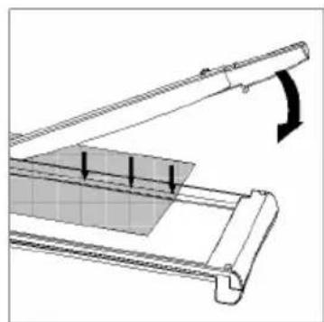
natural_image
Technical diagram of a mechanical assembly with a curved arrow indicating rotation or force (no text or symbols present)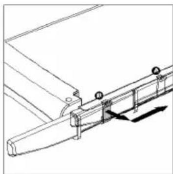
natural_image
Technical line drawing of a mechanical assembly with railings and mounting brackets (no text or symbols)natural_image
Illustration of a hand using a tool to interact with a mechanical component (no text or symbols visible)Bild 4
natural_image
Diagram of a mechanical device with rotating components and directional arrows indicating motion (no text or symbols)Bild
5
natural_image
Line drawing of a hand holding a pen, writing on a surface (no text or symbols)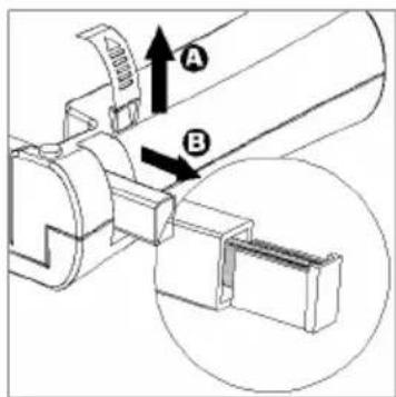
Bild 6 Bild 7
Bild
8
Service-Center Hattingen
Zum Kraftwerk 1
D-45527 Hattingen
Please observe the following information to ensure reliable operation of the cutting unit:
1 Read this manual thoroughly, observing the instructions and information in it when operating the machine.
2 Keep this operating manual in a safe place for future reference.
3 Before starting to use the device, set it down on a level, stable working base.
4 Never take hold of the knife blades when carrying the device or putting it away.
5 Use both hands to operate the device.
6 Keep loose clothing, ties, jewellery, long hair and other loose objects away from the cutting unit.
Risk of injury!
7 The device has been exclusively designed to cut paper.
8 Before cutting, remove any staples or paper clips from the document.
9 The blades must be neither greased nor ground.
10 The device must not be used if a blade or the housing of a blade is damaged.
11 The device must not be used if the knife protection is not installed properly.
12 Be careful not to cut your fingers when replacing blades. Avoid contact with the cutting blades at all times.
13 Keep the device out of the reach of children.
14 Children and minors may only use the device under the supervision of an adult.
15 The device is not intended to cut fingernails.
Exemption From Liability
We cannot guarantee that the information which relates to the technical properties of the product or to the product itself contained in this document is correct. The product and, where applicable, its accessories, described in this document are subject to constant improvement and further development. For this reason, we reserve the right to modify components, accessories, technical specifications and related documentation of the product described herein at any time without notice.
Intended Use
This cutting unit may only be used to cut paper, card, photo paper and laminating foil. Any other use is considered unintended use. Unauthorised modifications or reconstructions are not permitted.
Overview
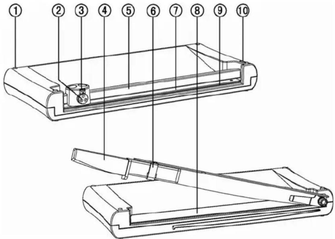
| 1 Rubber footpads 6 Locking latch | |
| 2 Selector knob 7 Translucent pressing rail | |
| 3 Setting lock | 8 Pressing rail with finger protection |
| 4 Guillotine arm 9 Blade | |
| 5 Guide rail 10 End cap |
Features
For cutting photos, card, printouts or laminated paper perfectly to size.
• Guillotine + pressing rail with finger protection
- Trimmer with 3 types of cut (straight cut, perforation and wave cut)
• Visual positioning aids in cm (lines, angles, scale)
• Rubber footpads for secure, non-slip base
• Dimensions: 405x195x50 mm (LxWxH)
• Weight: 1.1 kg
• Cutting length: 270 mm
Guillotine
Cutting capacity: Max. 5 sheets (80g/m²)
Pressing rail with finger protection
Cutting blade made of stainless steel
1 Place the cutting unit on a stable, level base with the guillotine side facing up.
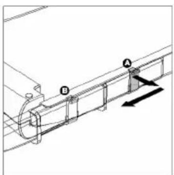
2 The guillotine arm is locked at the bottom edge of the cutting unit. To unlock the guillotine arm, pull the locking latch out a little (Fig. 1, A) and slide it towards the front to Position B (Fig. 1).
3 Move the guillotine arm upwards.
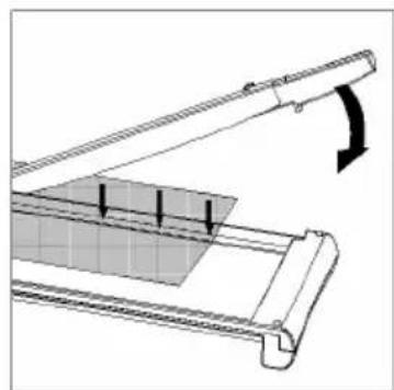
4 Place the material to be cut in the required position under the pressing rail and press the pressing rail down (Fig. 2).
5 Then use your other hand to move the guillotine arm down and cut the document (Fig. 2).
6 In order to lock the guillotine arm again after finishing your work, move the guillotine arm down as far as possible, pull the locking latch at Position B out a little and slide it back to Position A (Fig. 3).
natural_image
Technical line drawing of a mechanical conveyor belt system with labeled points A and B (no text or symbols beyond labels)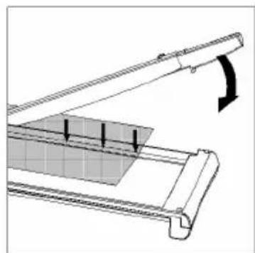
natural_image
Diagram of a mechanical assembly with a curved arrow indicating rotation or force direction (no text or symbols present)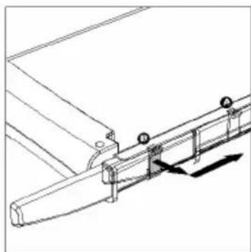
natural_image
Technical line drawing of a mechanical assembly with railings and mounting points (no text or symbols)Trimmer with integrated cut selector switch and setting lock.
Cutting functions:
- Straight cut Cutting capacity: max. 3 sheets (80g/m²)
- Perforation Cutting capacity: max. 3 sheets (80g/m²)
- Wave cut Cutting capacity: max. 3 sheets (80g/m²)
The blades are accommodated in a protected housing.
A spare blade is contained in the integrated storage compartment.
1 Place the cutting unit on a stable, level base with the trimmer side facing up.
2 Slide the cutting head to one side of the guide rail.
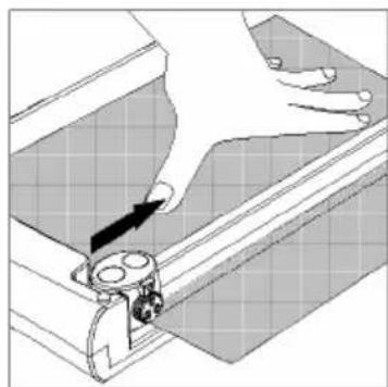
3 Place the material to be cut in the required position under the transparent pressing rail and hold the material in place with one hand when cutting.

Note: Hold the material to be cut securely, otherwise it could shift and be cut inaccurately. The raster and measuring system on the trim-mer's working surface serve as positioning aids.
4 To complete the cut, press the cutting head down and slide it along the guide rail to the other side.

Note: To prevent a faulty cutting edge, do not run the cutting head back again but remove the cut material directly after completing the cut.
natural_image
Diagram of a hand using a tool to adjust or install a mechanical component (no text or symbols visible)Fig. 4
Selecting the Type of Cut
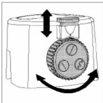
The trimmer has various types of cut available for selection: straight cut, perforation cut and wave cut. Select the type of cut you require.
1 Slide the lock for the trimmer's rotary cut selector upwards (Fig. 5). 2 Turn the selector knob until the symbol representing the required type of cut is under the lock (Fig. 5).
3 Press the lock for the trimmer's rotary cut selector downwards (Fig. 5).
natural_image
Diagram of a mechanical device with rotating components and directional arrows indicating motion (no text or symbols)Fig.
5
Replacing the Blade
The blade has four cutting edges (two on each side). When the quality of the cut is no longer clean, turn the blade so that one of the unused cutting edges will be used.
1 Slide the trimmer to one end of the guide rail.
2 Remove the blade out of the slot from the other side of the guide rail. Recesses are provided for this at both sides of the guide rail (Fig. 6).
3 Turn the blade so that a cutting edge which has still not been used is set to the working position and replace the blade back in the slot.
When all four cutting edges of the blade are worn, replace the blade.

Note: A spare blade is supplied in the storage compartment of the guide rail (Fig. 7).

natural_image
Line drawing of a hand holding a pen, writing on a surface (no text or symbols)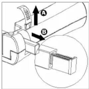
Fig. 6 Fig. 7
Replacing the Cutting Head
When the blade of the cutting head is damaged or worn, the cutting head must be replaced.
1 Remove the end cap of the guide rail from the base plate (Fig. 8, A) by pulling it upwards.
2 Pull the guide rail out of the base plate (Fig. 8, B).
3 Remove the cutting head from the guide rail (Fig. 8, C).
4 Replace the old cutting head with a new one.
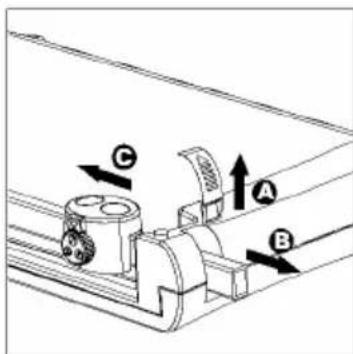
Fig. 8
5 Slide the guide rail back in the base plate and install the new cutting head in the process.
6 Insert the end cap from above on the opening at the end of the guide rail.

Note: Only the entire cutting head can be replaced. To obtain a new cutting head, please telephone our hotline.
Guarantee
It is essential to retain this guarantee!
Dear Customers,
We are pleased that you have chosen the reversible guillotine/trimmer from Olympia. Should a technical problem arise with regard to the equipment, please observe the following points:
- The period of guarantee for the equipment is 24 months.
- It is essential to keep the purchase receipt and original packing.
- The first line of action if a problem occurs is to contact our hotline.
0180 5 007514 (0.14 € per minute via the German landline)
Our expert personnel can frequently provide help over the phone.
- However, if the problem cannot be solved via telephone, please send the equipment to the following address in its original packing:
Service-Center Hattingen
Zum Kraftwerk 1
D-45527 Hattingen
Repairs under the terms of guarantee can only be completed when the purchase receipt is enclosed.
We are sorry for any inconvenience.
Yours faithfully
Olympia Business Systems
Vertriebs GmbH
Consumables
If the cutting head or blade becomes worn, please contact the hotline.
natural_image
Technical line drawing of a mechanical conveyor belt system with labeled points A and B (no text or symbols beyond labels)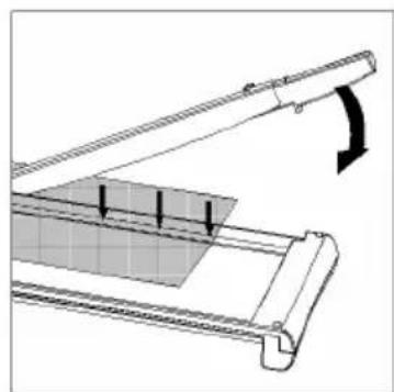
natural_image
Technical diagram of a mechanical assembly with a curved arrow indicating rotation or force (no text or symbols present)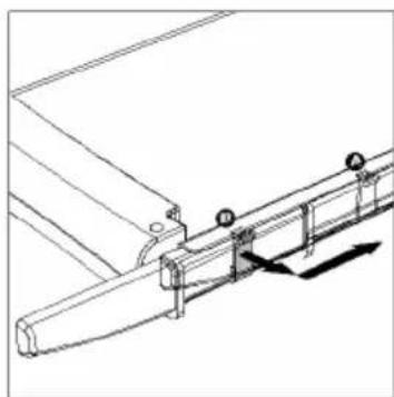
natural_image
Technical line drawing of a mechanical assembly with mounting brackets and a lever mechanism (no text or symbols)natural_image
Illustration of a hand using a tool to interact with a mechanical component (no text or symbols visible)Fig. 4
natural_image
Diagram of a mechanical device with rotating components and directional arrows indicating motion (no text or symbols)Fig. 5
natural_image
Line drawing of a hand holding a pen, writing on a line of parallel lines (no text or symbols present)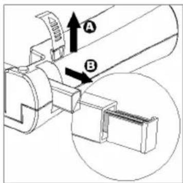
Fig. 6 Fig. 7
Fig. 8
Service-Center Hattingen
Zum Kraftwerk 1
D-45527 Hattingen
natural_image
Technical line drawing of a mechanical conveyor belt system with labeled points A and B (no text or symbols beyond labels)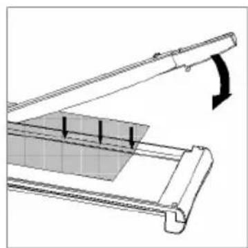
natural_image
Diagram of a mechanical lever system with a curved arrow indicating motion or force (no text or symbols present)
natural_image
Technical line drawing of a mechanical assembly with railings and mounting points (no text or symbols)Figura 1 Figura 2 Figura 3
natural_image
Illustration of a hand using a tool to lift a mechanical component (no text or symbols visible)Figura
4
natural_image
Diagram of a mechanical device with rotating components and directional arrows indicating motion (no text or symbols)Figura
5
Sustituir la regleta de corte
natural_image
Line drawing of a hand holding a pen, writing on a surface with parallel lines (no text or symbols)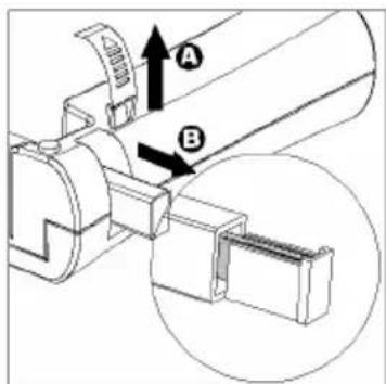
Figura 6 Figura 7
Figura
8
Olympia Business Systems
Vertriebs GmbH
Material de consumo
natural_image
Technical line drawing of a pipeline with labeled components A and B, showing directional arrows (no text or symbols beyond labels)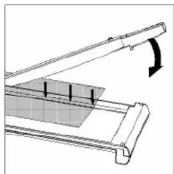
natural_image
Technical diagram of a mechanical assembly with a curved arrow indicating rotation or force direction (no text or symbols present)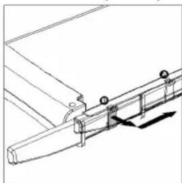
natural_image
Technical line drawing of a mechanical assembly with railings and mounting points (no text or symbols)natural_image
Illustration of a hand using a tool to interact with a mechanical component (no text or symbols visible)Afb.
4
Snede kiezen
natural_image
Diagram of a mechanical device with rotating components and directional arrows indicating motion (no text or symbols)Afb.
5
Snijlijst vervangen
natural_image
Line drawing of a hand holding a tool against a diagonal line (no text or symbols)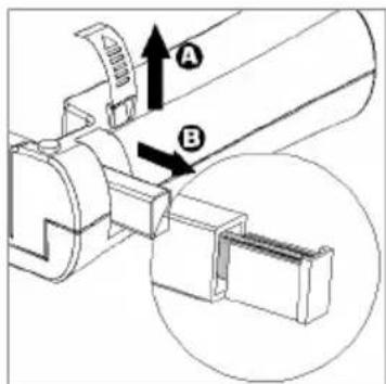
Afb. 6 Afb. 7
Afb. 8
Olympia Business Systems
Vertriebs GmbH
Verbruiksmateriaal
natural_image
Technical line drawing of a mechanical conveyor belt system with labeled points A and B (no text or symbols beyond labels)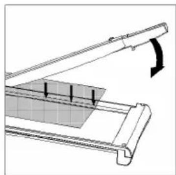
natural_image
Technical diagram of a mechanical assembly with a curved arrow indicating rotation or force (no text or symbols present)
natural_image
Technical line drawing of a mechanical assembly with railings and mounting brackets (no text or symbols)Figura 1 Figura 2 Figura 3
Taglierina a rullo
natural_image
Illustration of a hand using a tool to lift a metal bracket (no text or symbols visible)Figura
4
natural_image
Diagram of a mechanical device with rotating components and directional arrows indicating motion (no text or symbols)Figura
5
natural_image
Line drawing of a hand holding a tool, no text or symbols present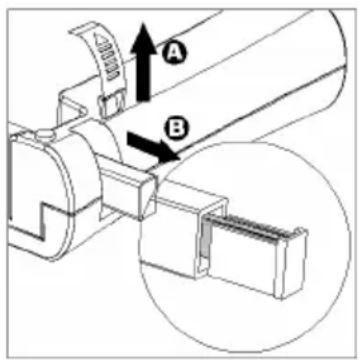
Figura 6 Figura 7
Figura 8
Olympia Business Systems
Vertriebs GmbH
natural_image
Technical line drawing of a mechanical conveyor belt system with labeled points A and B (no text or symbols beyond labels)obr.1
natural_image
Diagram of a mechanical assembly with a curved arrow indicating rotation or force direction (no text or symbols present)obr.2

natural_image
Technical line drawing of a mechanical linkage or rail assembly (no text or symbols)obr.3
Kotoučová řezačka
natural_image
Illustration of a hand using a tool to lift a wall-mounted device (no text or symbols visible)obr.
4
Volba vzhledu řezu
natural_image
Diagram of a mechanical device with rotating components and directional arrows indicating motion (no text or symbols)obr.
5
Výměna řezné lišty
natural_image
Line drawing of a hand holding a pen, writing on a surface with parallel lines (no text or symbols)obr.6

obr.
7
obr. 8
Service-Center Hattingen
Zum Kraftwerk 1
D-45527 Hattingen


- Français FR BE CH
- Exemption From Liability
- Intended Use
- Features
- Guillotine
- Selecting the Type of Cut
- Replacing the Blade
- Replacing the Cutting Head
- Guarantee
- Consumables
- Sustituir la regleta de corte
- Material de consumo
- Snede kiezen
- Snijlijst vervangen
- Verbruiksmateriaal
- Taglierina a rullo
- Kotoučová řezačka
- Volba vzhledu řezu
- Výměna řezné lišty
Brand : OLYMPIA
Model : Vario Duplex 4000
Category : Paper cutter