L 666 S - Lamp STEINEL - Free user manual and instructions
Find the device manual for free L 666 S STEINEL in PDF.
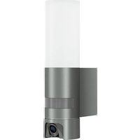
| Product type | LED wall light with motion detector |
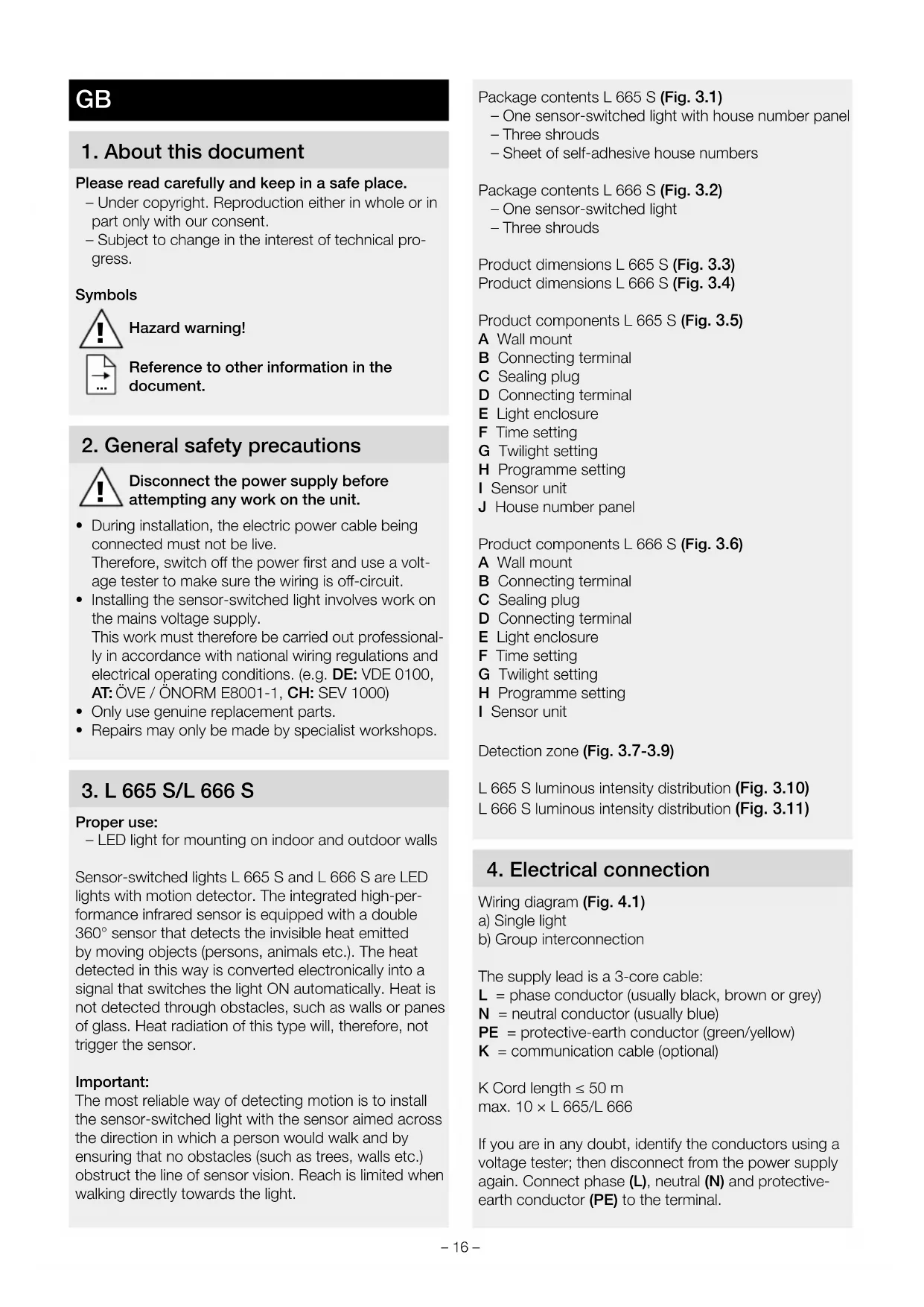
| Dimensions (H × W × D) | 269 × 102 × 122 mm |
| Power supply | 220-240 V, 50/60 Hz |
| Power consumption (P_on) | 8.50 W |
| Luminous flux | 596 lm |
| Color temperature | 3000 K (warm white) |
| Color rendering (Ra) | 82 |
| Detection angle | 360° with 90° angular aperture |
| Detection range | 7 m (tangential) |
| Adjustable time delay | 5 s - 15 min |
| Trigger threshold | 2 - 1000 lx |
| Programs | 4 programs: P1 standard, P2 comfort, P3 economical comfort, P4 Nightmatic |
| Forced on | Switchable 4 h |
| Orientation light function | Yes (approx. 10% power) |
| Protection rating | IP44 |
| Protection class | I |
| Impact resistance | IK07 |
| Ambient temperature | -20 °C to +50 °C |
| Average lifespan | 60,000 h (L70B50 at 25°C) |
| Energy efficiency class | E |
| Delivery contents | Wall light, 3 plug-in covers |
| Care and cleaning | Clean with a damp cloth, without detergent |
| Safety | Cut power before intervention; installation by a professional according to standard NF C-15100 |
| Spare parts and repairability | Light source not replaceable; replace entire luminaire in case of failure |
| Warranty | 5 years manufacturer |
Frequently Asked Questions - L 666 S STEINEL
User questions about L 666 S STEINEL
0 question about this device. Answer the ones you know or ask your own.
Ask a new question about this device
Download the instructions for your Lamp in PDF format for free! Find your manual L 666 S - STEINEL and take your electronic device back in hand. On this page are published all the documents necessary for the use of your device. L 666 S by STEINEL.
USER MANUAL L 666 S STEINEL

DE .... 10 Textteil beachten!
GB....16 Follow written instructions!
3.7
3.8
3.9
3.10 L 665 S
radar
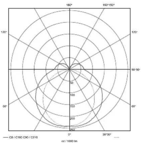
| Angle | Value | |-------|-------| | 0° | 250 | | 30° | 200 | | 60° | 150 | | 90° | 100 | | 120° | 50 | | 150° | 25 | | 180° | 10 |3.11
L 666 S
radar
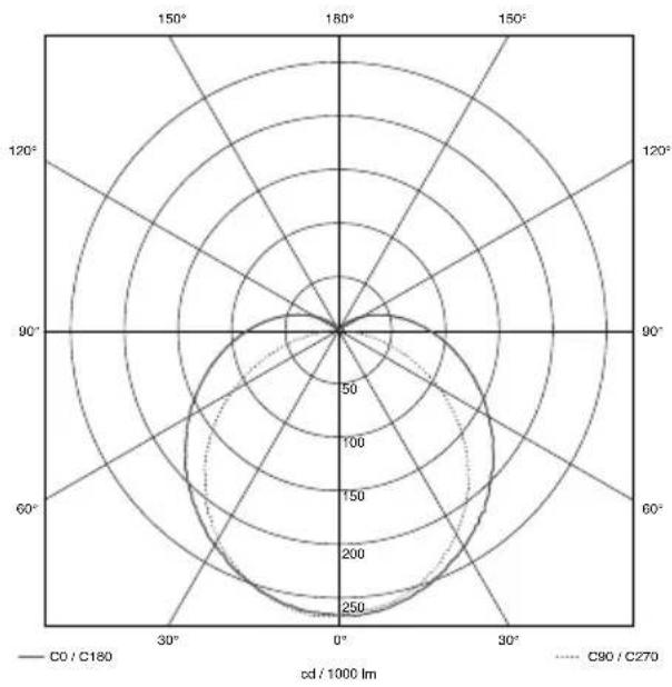
| cd / 1000 lm | C0 / C180 | C90 / C270 | | ------------ | --------- | ---------- | | 0° | 250 | 250 | | 30° | 250 | 250 | | 60° | 250 | 250 | | 90° | 250 | 250 | | 120° | 250 | 250 | | 150° | 250 | 250 |4.1
5.1
natural_image
Technical illustration of a mechanical assembly showing a cylindrical component being inserted into a housing, with no visible text or symbols.5.4
5.2
natural_image
Technical diagram of an electrical enclosure with internal components and directional arrows indicating assembly (no text or labels)5.5
5.3
natural_image
Technical diagram of an electrical enclosure with internal components and directional arrows indicating movement (no text or labels)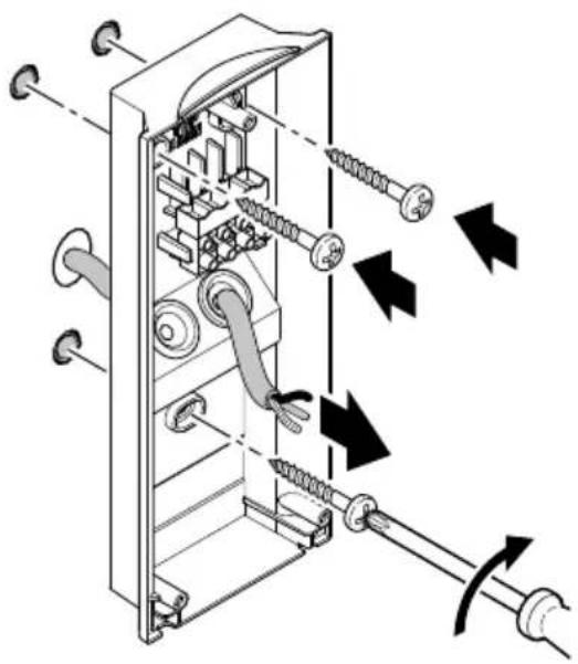
natural_image
Technical diagram of a mechanical device with springs and tubing, showing internal components and directional arrows (no text or labels)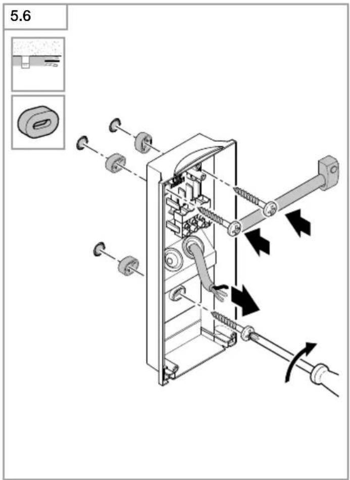

natural_image
Line drawing of a hand holding a small object, possibly a tool or device, with no visible text or symbols.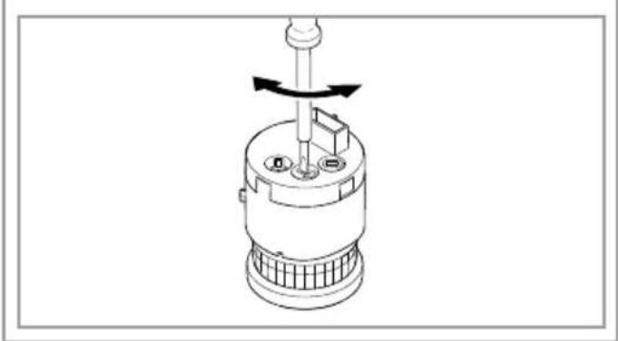
natural_image
Technical line drawing of a mechanical device with a rotating shaft and base, showing no text or symbols.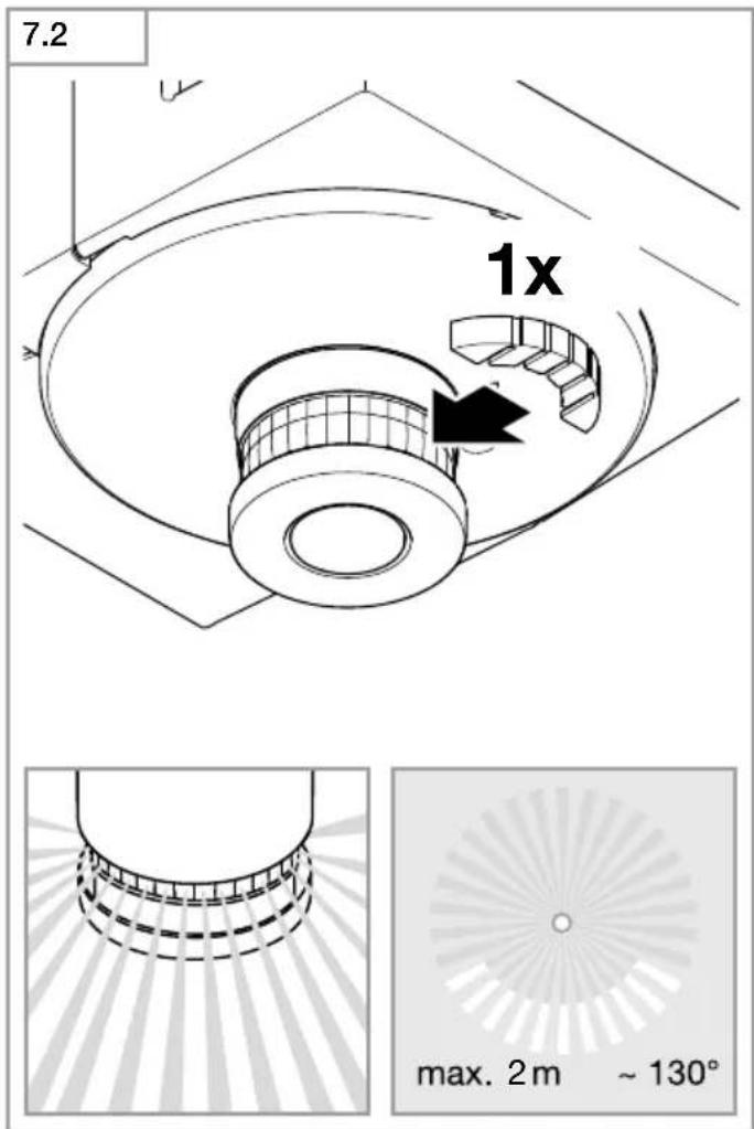
DE
Please read carefully and keep in a safe place.
– Under copyright. Reproduction either in whole or in part only with our consent.
- Subject to change in the interest of technical progress.
Symbols

Hazard warning!

Reference to other information in the document.
2. General safety precautions

Disconnect the power supply before attempting any work on the unit.
- During installation, the electric power cable being connected must not be live.
Therefore, switch off the power first and use a voltage tester to make sure the wiring is off-circuit. - Installing the sensor-switched light involves work on the mains voltage supply.
This work must therefore be carried out professionally in accordance with national wiring regulations and electrical operating conditions. (e.g. DE: VDE 0100, AT: ÖVE / ÖNORM E8001-1, CH: SEV 1000) - Only use genuine replacement parts.
• Repairs may only be made by specialist workshops.
3. L 665 S/L 666 S
Proper use:
– LED light for mounting on indoor and outdoor walls
Sensor-switched lights L 665 S and L 666 S are LED lights with motion detector. The integrated high-performance infrared sensor is equipped with a double 360° sensor that detects the invisible heat emitted by moving objects (persons, animals etc.). The heat detected in this way is converted electronically into a signal that switches the light ON automatically. Heat is not detected through obstacles, such as walls or panes of glass. Heat radiation of this type will, therefore, not trigger the sensor.
Important:
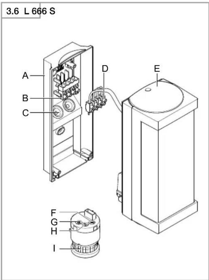
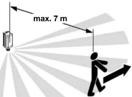
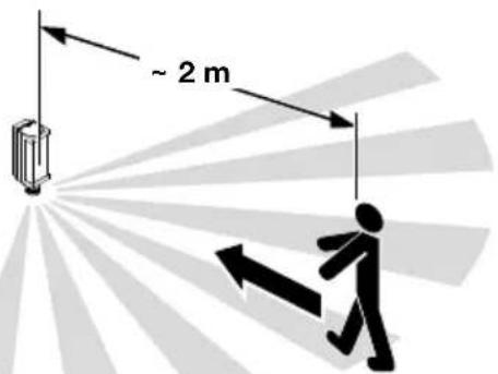
The most reliable way of detecting motion is to install the sensor-switched light with the sensor aimed across the direction in which a person would walk and by ensuring that no obstacles (such as trees, walls etc.) obstruct the line of sensor vision. Reach is limited when walking directly towards the light.
Package contents L 665 S (Fig. 3.1)
- One sensor-switched light with house number panel
- Three shrouds
– Sheet of self-adhesive house numbers
Package contents L 666 S (Fig. 3.2)
- One sensor-switched light
- Three shrouds
Product dimensions L 665 S (Fig. 3.3)
Product dimensions L 666 S (Fig. 3.4)
Product components L 665 S (Fig. 3.5)
A Wall mount
B Connecting terminal
C Sealing plug
D Connecting terminal
E Light enclosure
F Time setting
G Twilight setting
H Programme setting
I Sensor unit
J House number panel
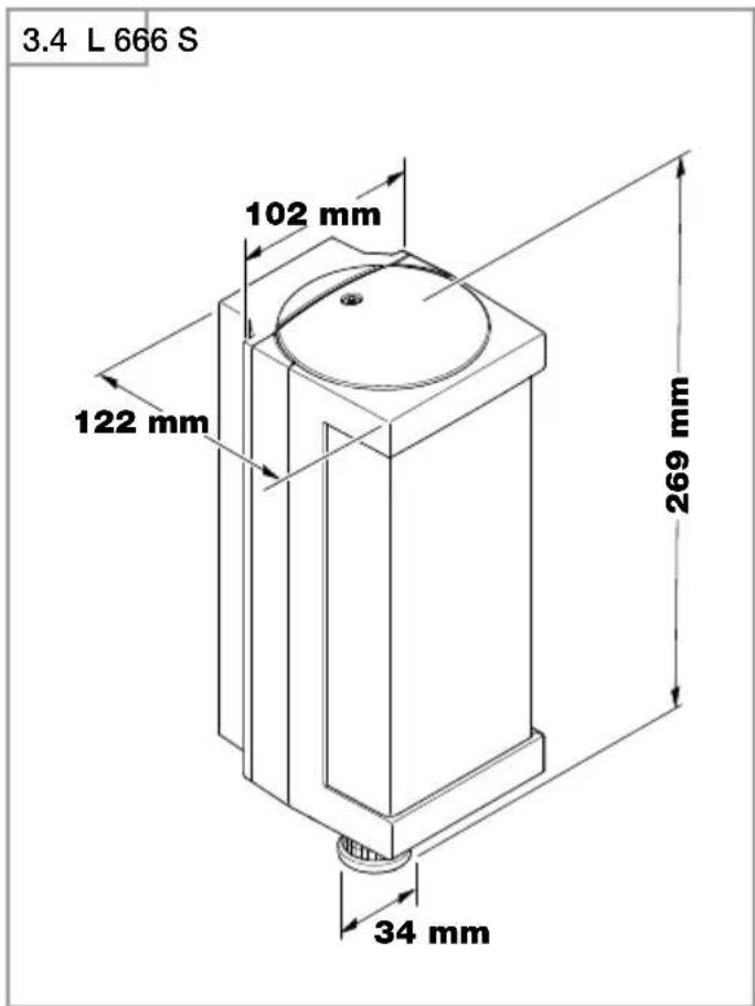
Product components L 666 S (Fig. 3.6)
A Wall mount
B Connecting terminal
C Sealing plug
D Connecting terminal
E Light enclosure
F Time setting
G Twilight setting
H Programme setting
I Sensor unit
Detection zone (Fig. 3.7-3.9)
L 665 S luminous intensity distribution (Fig. 3.10)
L 666 S luminous intensity distribution (Fig. 3.11)
4. Electrical connection
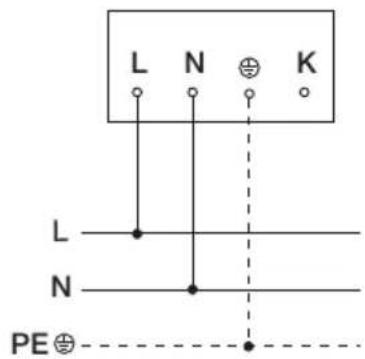
Wiring diagram (Fig. 4.1)
a) Single light
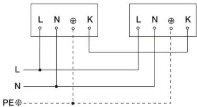
b) Group interconnection
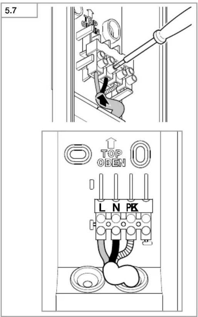
The supply lead is a 3-core cable:
L = phase conductor (usually black, brown or grey)
N = neutral conductor (usually blue)
PE = protective-earth conductor (green/yellow)
K = communication cable (optional)
K Cord length ≤ 50 m
max. 10 × L 665/L 666
If you are in any doubt, identify the conductors using a voltage tester; then disconnect from the power supply again. Connect phase (L), neutral (N) and protective-earth conductor (PE) to the terminal.
Important:
Incorrectly wired connections will produce a short circuit later on in the product or fuse box. In this case, you must identify the individual conductors once again and reconnect them. A mains power switch for turning the unit ON and OFF may of course be installed in the mains supply lead.
The light source in this luminaire cannot be replaced. If the light source needs to be replaced (e.g. at the end of its service life), the complete luminaire must be replaced.
Group behaviour
Communication cable (K) permits internal STEINEL group interconnection of L 665 S and L 666 S.
As many as 10 lights can be interconnected with each other. Maximum communication cable length is 50 m. The first light in a group to detect movement switches the entire group ON. If no further movement is detected after the time setting selected, the last light in a group to detect movement switches the entire group OFF.
Note:
- No voltage must be connected to the communication cable. Do no actuate any external loads.
– Within the interconnected group, all lights operate in line with their specific control dials.
– The same programme must be selected for all lights.
5. Mounting
- Check all components for damage.
- Do not use the product if it is damaged.
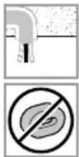
- When installing the sensor-switched light, make sure the installation site is not exposed to vibration.
- Select an appropriate mounting location, taking the reach and motion detection into consideration.
Mounting procedure
- Switch OFF power supply (Fig. 4.1)
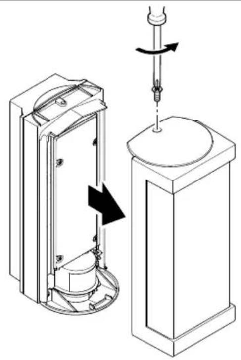
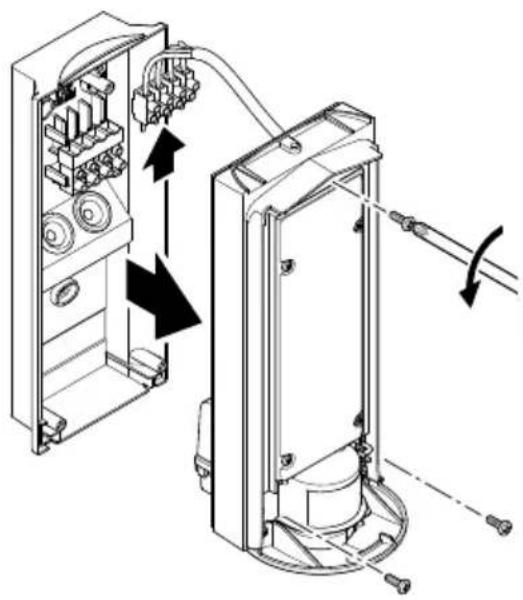
- Unscrew light enclosure from wall mount (Fig. 5.1)
- Disconnect terminal (Fig. 5.2)
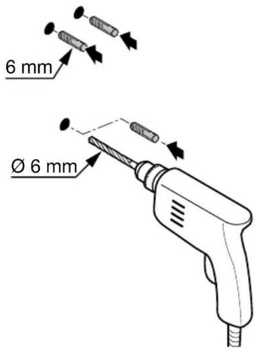
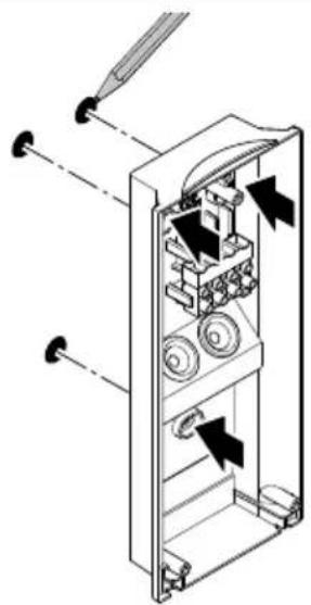
• Mark drill holes (Fig. 5.3) - Drill holes and insert wall plugs (Fig. 5.4)
• Installation with concealed power supply lead (Fig. 5.5)
• Installation with surface-mounted power supply lead (Fig. 5.6) - Connect conductors (Fig. 5.7)
L 665 S
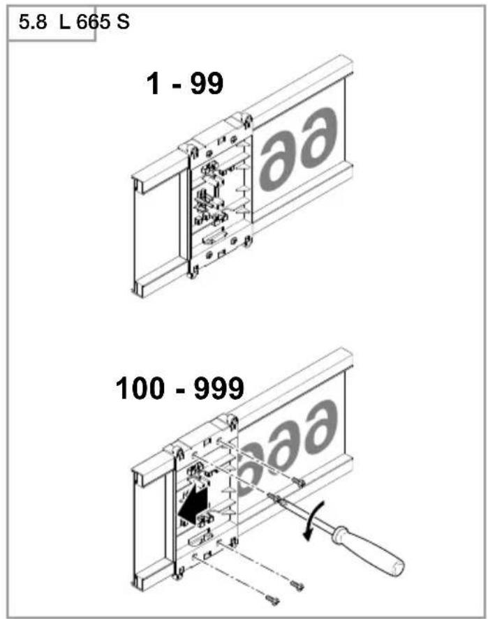
- Adjust house number panel (Fig. 5.8)
- Fit house number panel and screw into place (Fig. 5.8)
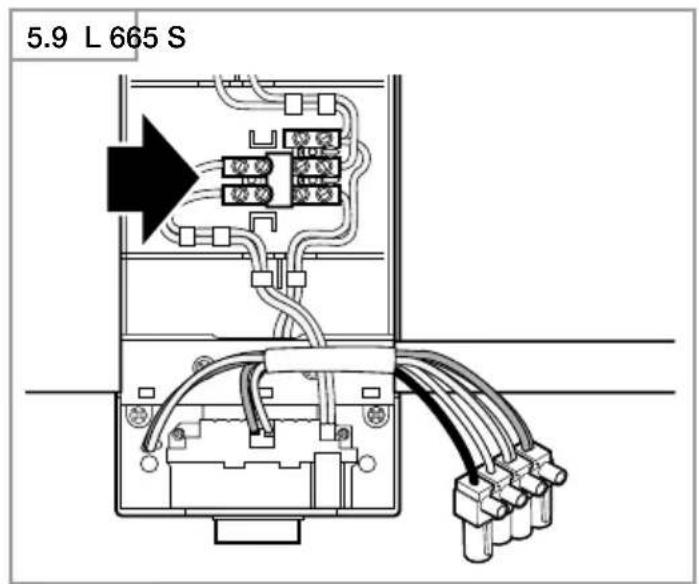
- Interconnect terminal for house number panel (Fig. 5.9)
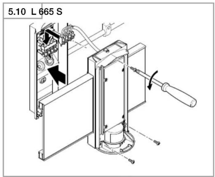
- Connect terminal (Fig. 5.10)
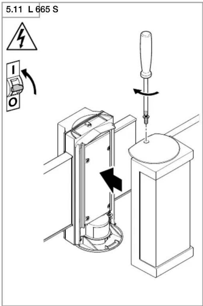
- Screw light enclosure to wall mount (Fig. 5.11)
- Switch ON power supply (Fig. 5.11)
- Apply numbers from sheet of self-adhesive house numbers (Fig. 5.12)
Note: refer to sheet of self-adhesive house numbers for further details on applying them.
L 666 S
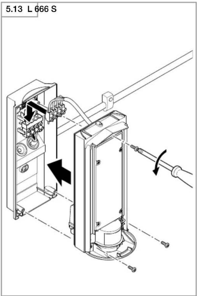
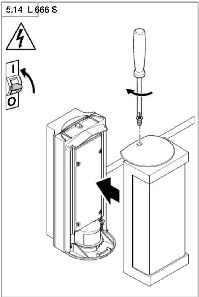
- Connect terminal (Fig. 5.13)
- Screw light enclosure to wall mount (Fig. 5.14)
- Switch ON power supply (Fig. 5.14)
• Make settings → "6. Function"
6. Function
Factory settings
Programme setting: P 1
Twilight level: 1000 lux
Time setting: 5 seconds
Once installed, the sensor-switched light can be put into operation. Control dials are provided on the sensor unit for selecting the time-, twilight- and programme settings.
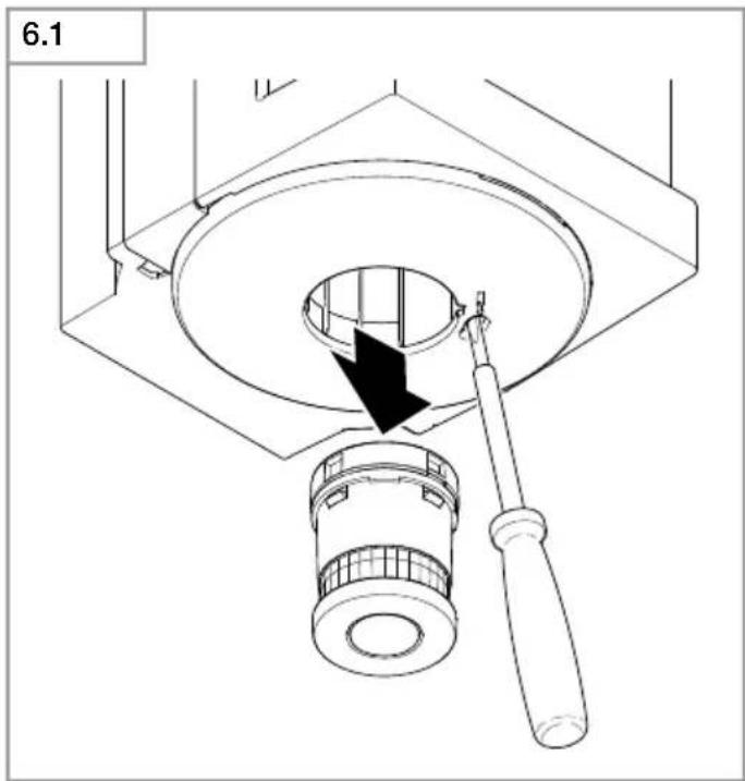
- Remove the sensor after pressing the locking tab with a flat-tip screwdriver (Fig. 6.1)
- The sensor-switched light switches to manual override (permanently ON)
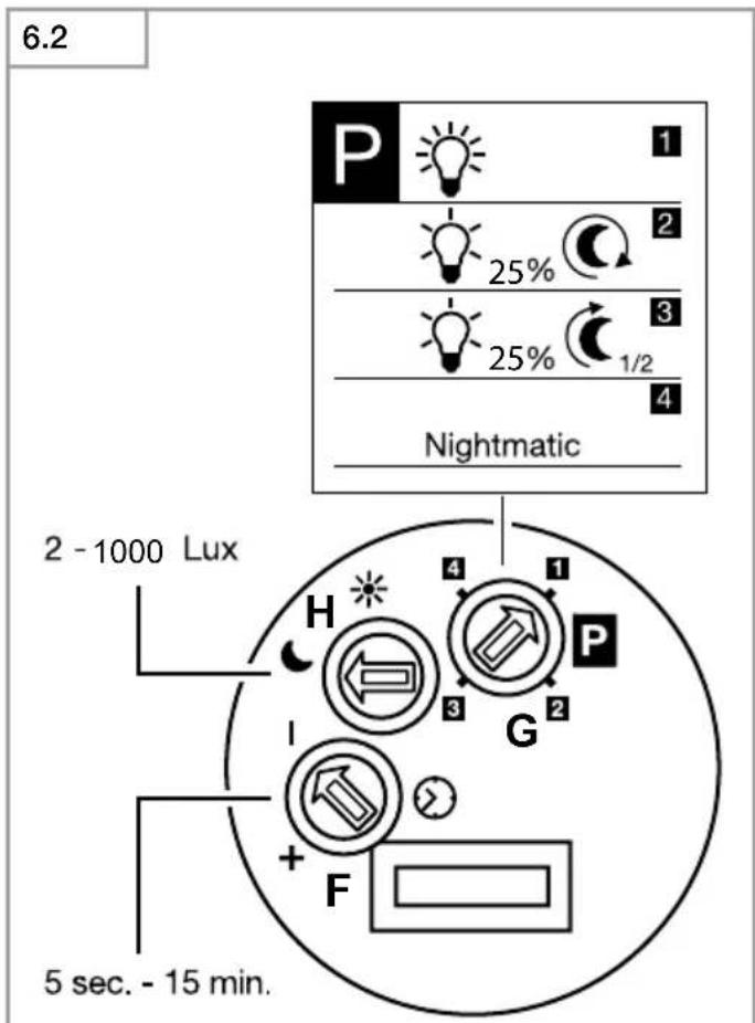
- Make settings with a screwdriver (Fig. 6.2)
P1 Standard programme (controller 6.2/G)
- Soft light start / no basic light level
What is soft light start?
The sensor-switched light features a soft light start function. This means that when turned ON, the light is not switched directly to maximum output but constantly builds up brightness to 100% within a short period of time. Brightness is also gradually reduced when the light is switched OFF.
P2 User-friendly programme
- Soft light start + basic light level
– Basic light level ON from twilight setting selected
What is basic light level?
Basic light level provides continuous night-time illumination at approx. 25% light output. The light only switches to maximum output (100%) for the time selected in
response to movement in the detection zone. The light then returns to the basic light level (approx. 25%).
P3 User-friendly economy programme
- Soft light start + basic light level until the middle of the night
– Basic light level ON from twilight setting selected until the middle of the night
How does the user-friendly economy programme work?
The sensor-switched light does not have an integrated clock. The middle of the night is only determined on the basis of the length of darkness phases. To work perfectly, therefore, it is important for the sensor-switched light to be permanently connected to the power supply during this period. During the first night (calibration phase) basic light level remains activated throughout the night. The values are saved even in the event of a mains power failure. We do not recommend interrupting the power supply during the programme. As the values are determined over several nights, the sensor-switched light should, in the event of any fault occurring, be monitored over several nights to ascertain whether the switch-off time moves towards midnight.
P4 Nightmatic programme
- Soft light start, no basic light level, no movement evaluation
- Switches ON at 100% if the light level falls below the level set
Note: if the light has a house number panel it switches ON in all four programmes when the level of light falls below the twilight setting.
Twilight setting (controller 6.2/H)
The chosen response threshold can be infinitely varied from approx. 2 to 1000 lux.
- Control dial set to ⚙ = daylight mode (depending on ambient brightness)
- Control dial set to = twilight mode (approx. 2 lux)
To adjust the detection zone in daylight operation, the control dial must be set to ⚙ (daylight operation).
Time setting (controller 6.2/F)
The light's ON time can be set to any period from approx. 5 seconds to a maximum of 15 minutes. Any movement detected before this time elapses will restart the timer.
Manual override function
If a mains switch is installed in the mains supply lead, the following functions are available in addition to simply switching light ON and OFF:
Sensor operation
1) Switch light ON (when light is OFF):
Switch OFF and ON once.
Light stays ON for the period selected.
2) Switch light OFF (when light is ON):
Switch OFF and ON once.
Light goes out or switches to sensor operation.
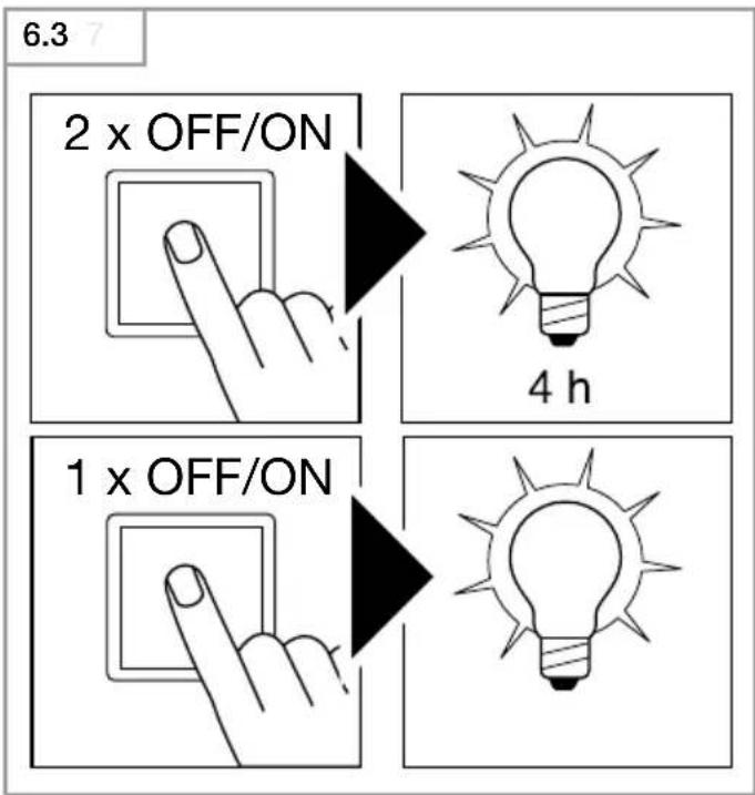
Manual override (Fig. 6.3)
1) Activate manual override:
Switch OFF and ON twice. The light is set to stay ON for 4 hours (red LED lights up behind the lens). Then it returns automatically to sensor operation (red LED off).
2) Deactivate manual override:
Switch OFF and ON once. Light goes out or switches to sensor operation.
Important:
Switching must take place within 0.2 to 1 second.
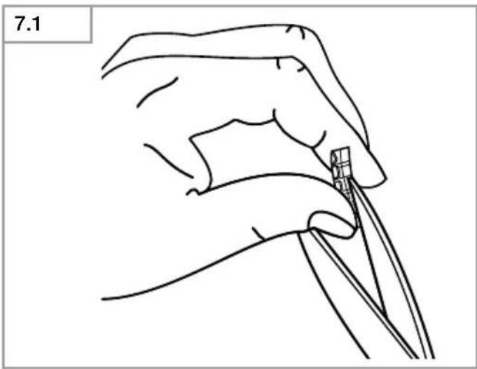
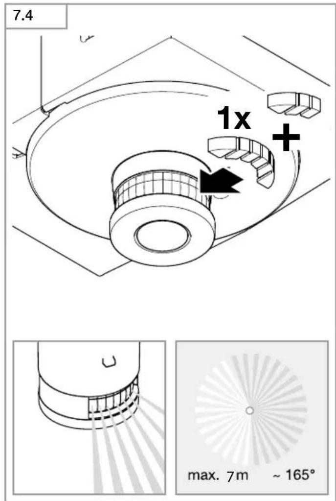
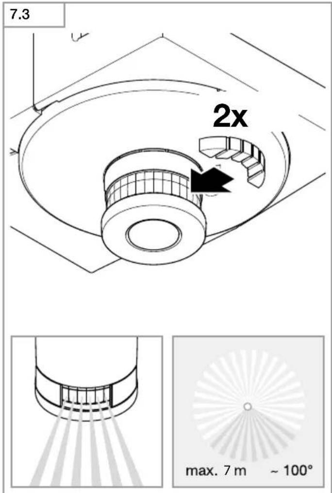
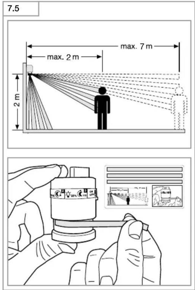
Adjusting the detection zone (Fig. 7.1-7.5)
The detection zone can be limited to suit requirements. The shrouds supplied with the unit can be used to mask out as many lens segments as you wish. This prevents the light from being activated unintentionally, e.g. by cars, passersby etc., and allows you to target danger spots. The shrouds can be cut along the grooved vertical divisions. Then you simply clip them onto the lens.
7. Maintenance and care
The product requires no maintenance.
The light can be cleaned with a damp cloth (without detergents) if dirty.
Important note: the control gear cannot be replaced.
8. Disposal
Electrical and electronic equipment, accessories and packaging must be recycled in an environmentally compatible manner.

Do not dispose of electrical and electronic equipment as domestic waste.
EU countries only:
Under the current European Directive on Waste Electrical and Electronic Equipment and its implementation in national law, electrical and electronic equipment no longer suitable for use must be collected separately and recycled in an environmentally compatible manner.
9. Manufacturer's Warranty
As purchaser, you are entitled to your statutory rights against the vendor. If these rights exist in your country, they are neither curtailed nor restricted by our Warranty Declaration. We guarantee that your STEINEL Professional sensor product will remain in perfect condition and proper working order for a period of 5 years. We guarantee that this product is free from material-, manufacturing- and design flaws. In addition, we guarantee that all electronic components and cables function in the proper manner and that all materials used and their surfaces are without defects.
Making Claims
If you wish to make a claim, please send your product complete and carriage paid with the original receipt of purchase, which must show the date of purchase and product designation, either to your retailer or contact us at STEINEL (UK) Limited, 25 Manasty Road, Axis Park, Orton Southgate, Peterborough, PE2 6UP, for a returns number. For this reason, we recommend that you keep your receipt of purchase in a safe place until the warranty period expires. STEINEL shall assume no liability for the costs or risks involved in returning a product.
For information on making claims under the terms of the warranty, please go to www.steinel-professional.de/garantie
If you have a warranty claim or would like to ask any question regarding your product, you are welcome to call us at any time on our Service Hotline 01733 366700.
5 YEAR MANUFACTURER'S WARRANTY
10. Technical specifications
Dimensions (H × W × D) L 665 S: 269 × 326 × 122 mm
L 666 S: 269 × 102 × 122 mm
Supply voltage 220-240 V, 50/60 Hz
Luminous flux L 665 S: 611 lm
L 666 S: 596 lm
Power consumption ( P_on ) L 665 S: 10.40 W
L 666 S: 8.50 W
Efficiency L 665 S: 59 lm/W
L 666 S: 70 lm/W
Standby (sensor P_sb ) L 665 S: 0.46 W
L 666 S: 0.48 W
Colour temperature 3,000 K (warm white)
Colour rendering index R
a = 82
Average rated life expectancy L70B50 at 25°C: 60,000 hours
Colour consistency SDCM Starting value 3
Luminous intensity distribution
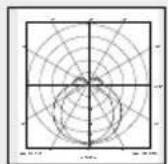
L 665 S
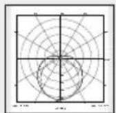
L 666 S
| Maximum mounting height | 2.50 m |
| Sensor technology | Passive infrared |
| Angle of coverage | 360° with 90° angle of aperture and sneak-by guard |
| Detection reach | 7 m tangentially |
| Time setting | 5 s - 15 min |
| Twilight setting | 2-1,000 lux |
| Basic light level function | 10% |
| Programme setting | 4 programmes geared to practical needs |
| Permanent light | selectable, 4 h |
| IP rating | IP44 |
| Protection class | I |
| Impact resistance | IK07 |
| Ambient temperature | -20 to +50°C |
| Energy efficiency class | This product contains an "F" (L 665 S) / "E" (L 666 S) energy efficiency class light source. |
11. Troubleshooting
Malfunction Cause Remedy
| Sensor-switched light without power | ■ Fuse has tripped, not switched on, break in wiring■ Short circuit | ■ Activate, change fuse, turn on mains switch, check wiring with voltage tester■ Check connections |
| Sensor-switched light will not switch ON | ■ Twilight setting in night-time mode during daytime operation■ Mains switch off■ Fuse has tripped■ Detection zone not correctly adjusted | ■ Reset■ Switch on■ Activate, change fuse, check connection if necessary■ Readjust |
| Sensor-switched light will not switch OFF | ■ Continued movement within the detection zone■ Sensor unit is not properly engaged■ Sensor light is in the calibration phase (user-friendly economy programme)■ Position wi-fi device very close to the sensor | ■ Check detection zone and readjust if necessary■ Lightly press sensor unit to clip it into place■ See note on user-friendly economy programme■ Increase distance between wi-fi device and sensor >3m |
| IEDs do not go out at about midnight as desired | ■ External light source (e.G. Other motion detector or light) is deactivating the sensor-switched light | ■ Shade the sensor-switched light from extraneous light, then monitor the sensor-switched light for several days. It takes some time to return to the correct value |
| LEDs do not switch OFF completely | ■ User-friendly programme selected | ■ Turn programme selector dial to 4 |
| Sensor-switched light switching ON when it should not | ■ Wind is moving trees and bushes in the detection zone■ Cars in the street are detected■ Sudden temperature changes due to weather (wind, rain, snow) or air expelled from fans, open windows. | ■ Use shrouds to define detection zone precisely■ Use shrouds to define detection zone precisely■ Adjust detection zone or install in a different place |
| Sensor-switched light's reach has changed | ■ Differing ambient temperatures | ■ Use shrouds to define detection zone precisely |
FR
P2 Programma comfort
8. Eliminación
Programinnstilling: P 1
Skumringsinnstilling: 1000 lux
Tidsinnstilling: 5 sekunder
Permanent lys (ill. 6.3)
1) Tenne permanent lys:
8. Απόσυρση
P4 Nightmatic program
P4 Nightmatic program
5 ANI GARANTIA PRODUCATORULUI
- Date tehnice
P4 program Nightmatic
5 METU GAMINTOJÓ GARANTIJA
8. Утилизация
natural_image
World map silhouette in grayscale, showing continents and oceans without any text or labelsContact
www.steinel.de/contact