PWDS 920 B2 - Sander PARKSIDE - Free user manual and instructions
Find the device manual for free PWDS 920 B2 PARKSIDE in PDF.
| Product Type | Wall and ceiling sander |
| Brand | Parkside |
| Model | PWDS 920 B2 |
| Rated voltage | 220-240 V ~, 50-60 Hz |
| Power consumption | 710 W |
| Oscillation speed (adjustable) | 800 - 1800 min⁻¹ |
| Sanding pad diameter | 215 mm |
| Abrasive disc diameter | 225 mm |
| Power cord length | 4.5 m |
| Protection class | II (double insulation) |
| Sound pressure level | 90 dB(A) (uncertainty 3 dB) |
| Sound power level | 101 dB(A) (uncertainty 3 dB) |
| Vibration emission (sanding) | < 2.5 m/s² (uncertainty 1.5 m/s²) |
| Work area LED lighting | Yes, with switch |
| Speed control | Yes, via + and - buttons |
| Telescopic extension | Yes, adjustable length |
| Head orientation | 30° sideways, 30° forward, 90° backward |
| Brush edge | Yes, for surface protection |
| Package contents | 1 sander, 1 extension, 1 suction hose, 2 adapters, 6 abrasive discs (grit 80-240), 1 screwdriver, 1 Allen key, 1 pair of replacement carbon brushes, manual |
| Routine maintenance | Clean with dry cloth, replace carbon brushes, replace sanding pad |
| Recommended safety | Safety goggles, hearing protection, dust mask, unplug before maintenance |
| Warranty | 3 years |
| Customer service France | 0800904879, owim@lidl.fr |
| Customer service Belgium | 080071011, owim@lidl.be |
Frequently Asked Questions - PWDS 920 B2 PARKSIDE
User questions about PWDS 920 B2 PARKSIDE
0 question about this device. Answer the ones you know or ask your own.
Ask a new question about this device
Download the instructions for your Sander in PDF format for free! Find your manual PWDS 920 B2 - PARKSIDE and take your electronic device back in hand. On this page are published all the documents necessary for the use of your device. PWDS 920 B2 by PARKSIDE.
USER MANUAL PWDS 920 B2 PARKSIDE
text_image
PDF ONLINE www.lidl-service.com
natural_image
Black metal detector with attached sensor and cable (no text or symbols visible)WAND- UND DECKENSCHLEIFER / DRYWALL SANDER / PONCEUSE MURS ET PLAFONDS PWDS 920 B2
DE AT CH
WAND- UND DECKENSCHLEIFER
Operation and safety notes
Translation of the original instructions
FR BE
PONCEUSE MURS ET PLAFONDS
natural_image
Technical line drawing of a mechanical assembly with no visible text or symbols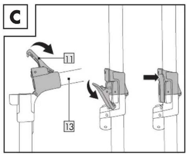
text_image
C 11 13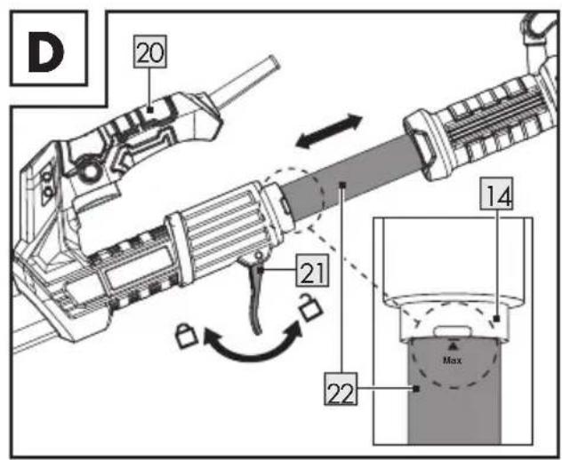
text_image
D 20 21 14 22 Max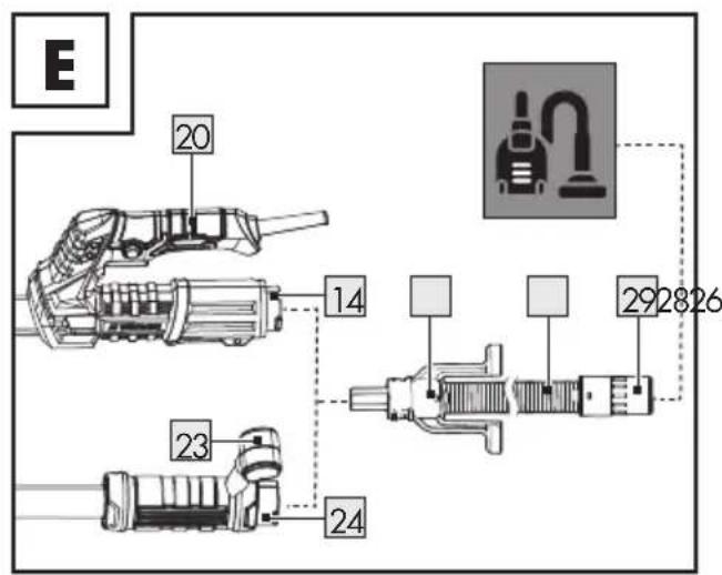
text_image
E 20 14 292826 23 24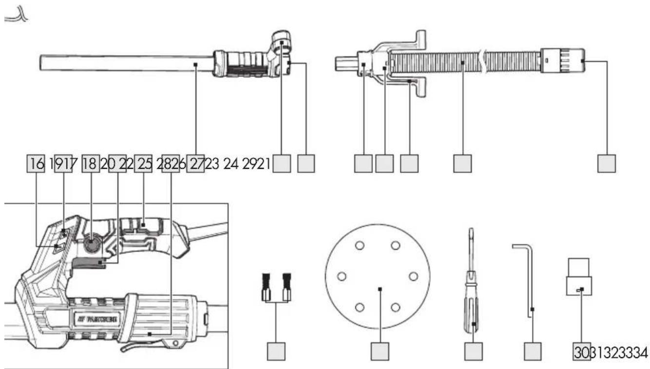
text_image
F 14/24 25 26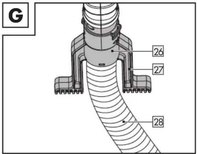
text_image
G 26 27 28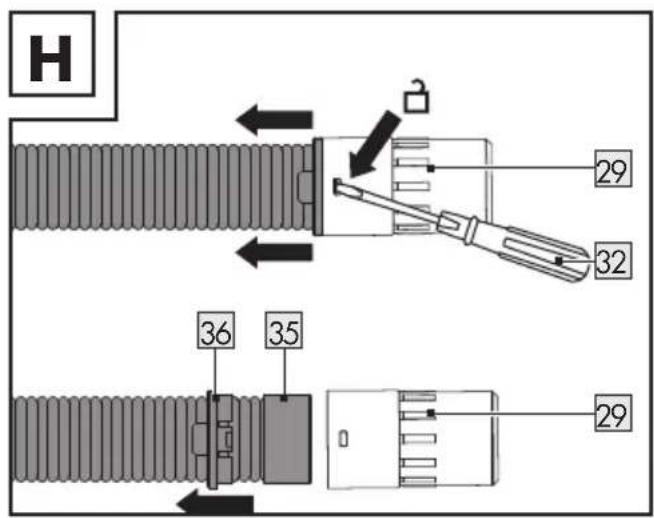
text_image
H 29 32 36 35 29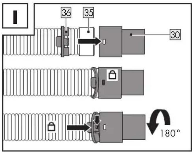
text_image
36 35 30 180°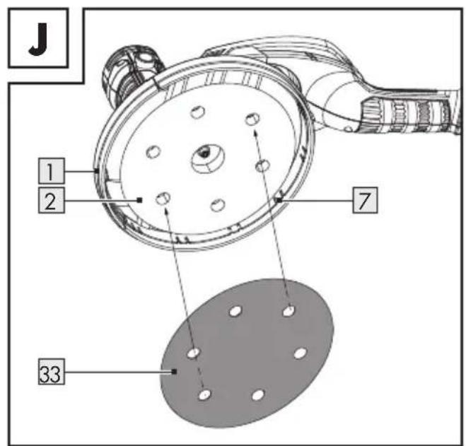
text_image
J 1 2 7 33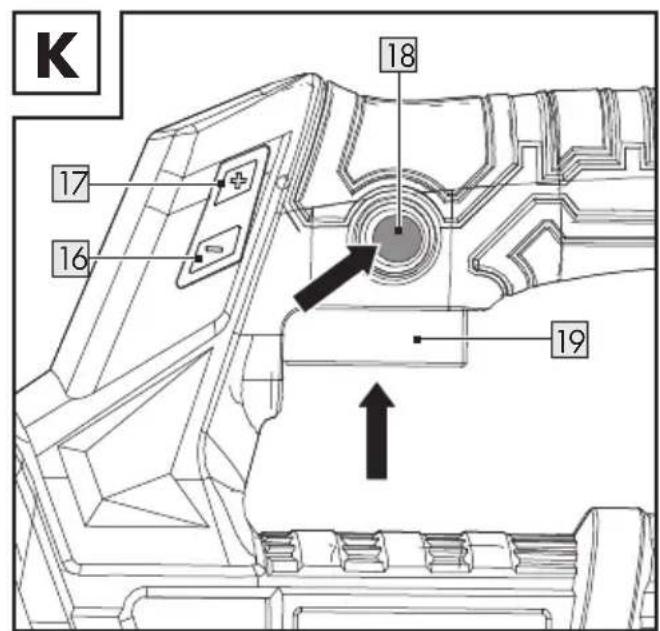
text_image
K 17 16 18 19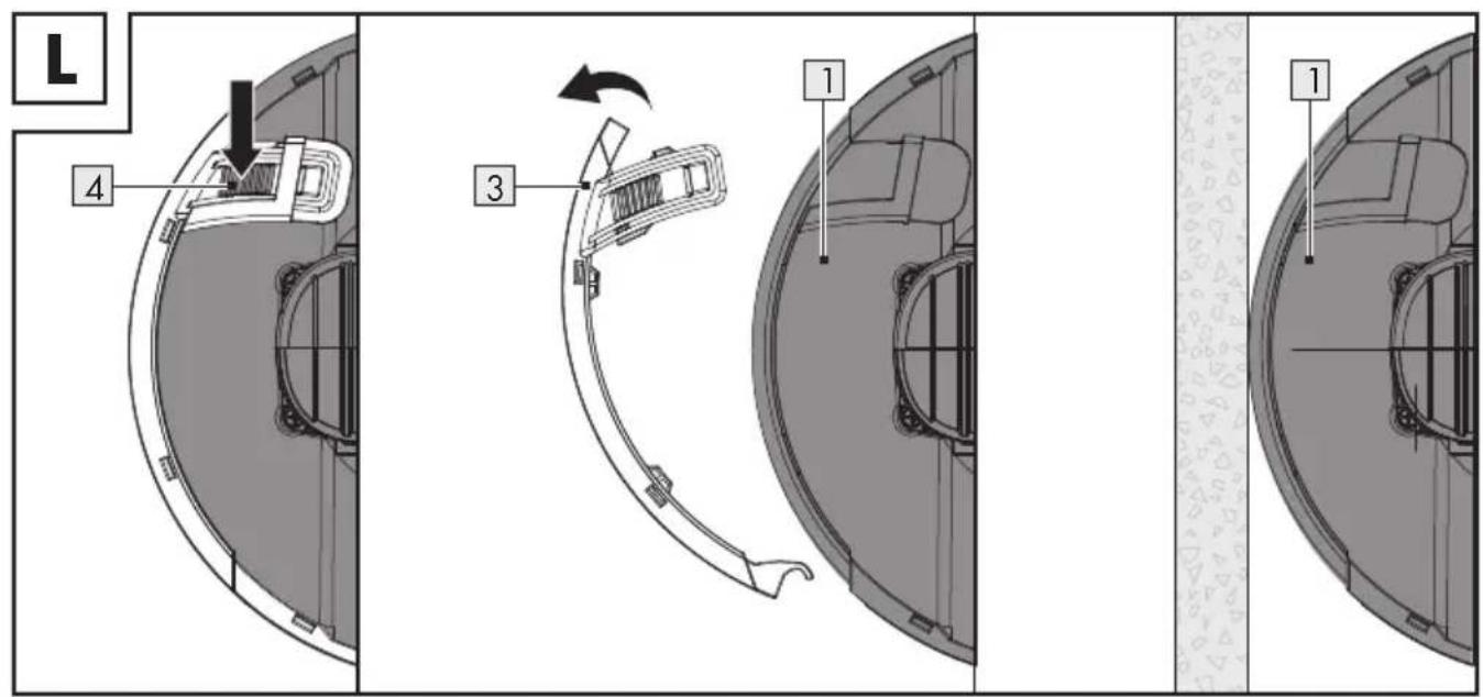
text_image
L 4 3 1 1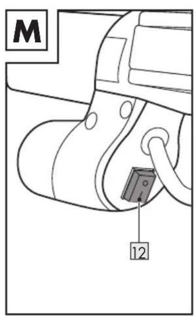
text_image
M 12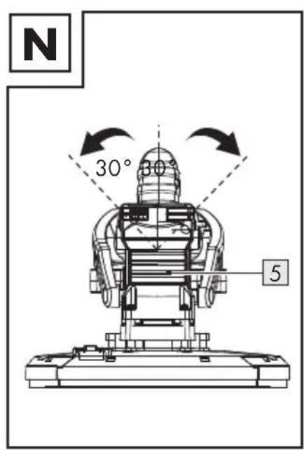
text_image
N 30° 30° 5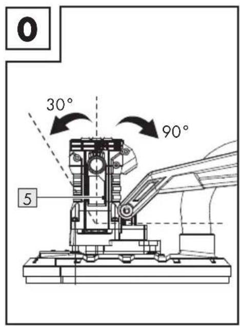
text_image
0 30° 90° 5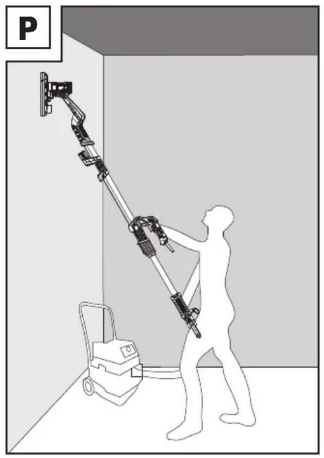
natural_image
Silhouette of a person using a mobile phone to lift a wall-mounted device, no text or symbols visible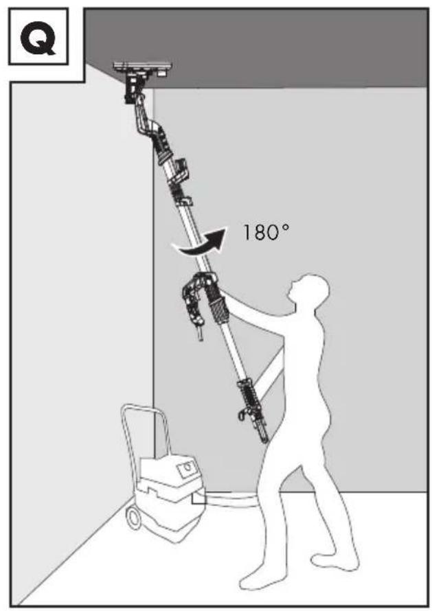
text_image
Q 180°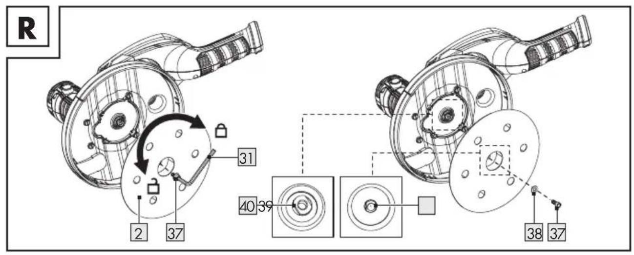
text_image
R 2 37 31 40 39 38 37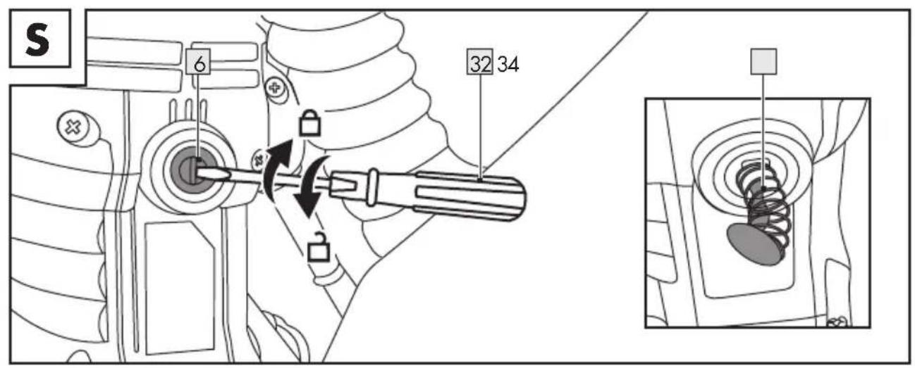
text_image
S 6 32 34Authorised Signatory
DE
Warnings and symbols used Page 31
Introduction Page 32
Intended use.... Page 32
Scope of delivery.... Page 33
Parts description.... Page 33
Technical data Page 34
Safety instructions.... Page 35
General power tool safety warnings....Page 35
Safety instructions for all operations – Safety warnings common for sanding. . . . . . . . . Page 38
Safety warnings specific for sanding operations.... Page 40
Additional safety instructions Page 40
Vibration and noise reduction ...... Page 41
Remaining risks.... Page 41
Before first use Page 41
Accessories Page 41
Unpacking Page 42
Assembly Page 42
Unfolding the shaft.... Page 42
Attaching the telescopic extension shaft 42
Connecting the vacuum hose.... Page 43
Changing the hose adaptor.... Page 43
Selecting sanding paper ...... Page 44
Attaching and removing sanding paper 44
Function of the brush edge.... Page 44
Operation.... Page 45
Connecting to power supply Page 45
Switching on and off Page 45
Adjusting the speed.... Page 45
Removing and attaching the detachable front guard cover.... Page 45
Switching the LED working lamp on and off Page 46
Rotating and tilting the motor housing....Page 46
Working instructions Page 46
After use Page 46
Cleaning and care Page 46
Cleaning. Page 47
Maintenance Page 47
Repair....Page 48
Storage Page 48
Transportation Page 48
Troubleshooting Page 49
Disposal Page 50
Warranty Page 51
Warranty claim procedure.... Page 51
Service Page 51
EC declaration of conformity.... Page 52
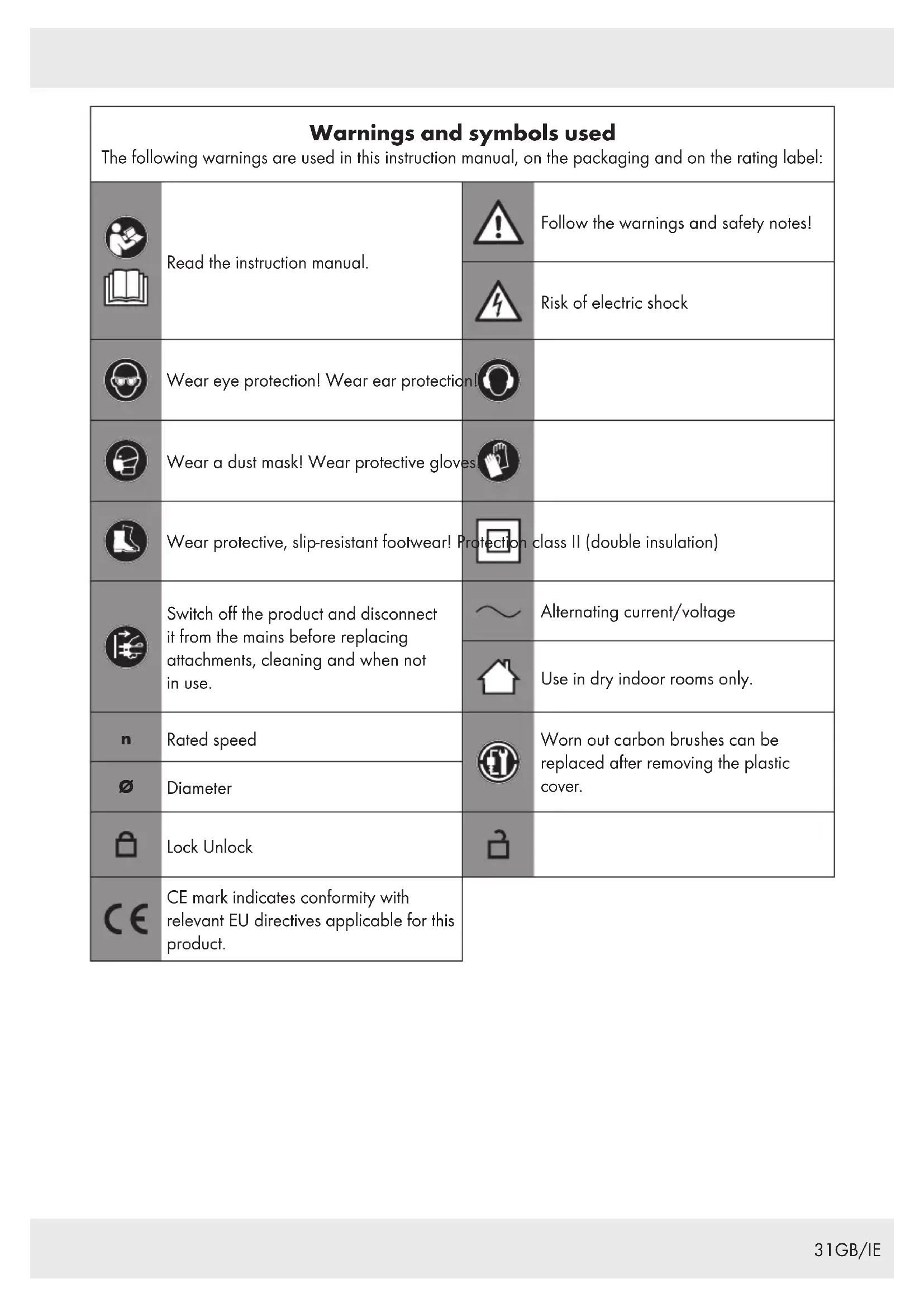
| Warnings and symbols usedThe following warnings are used in this instruction manual, on the packaging and on the rating label: | |||
 | Read the instruction manual. | Follow the warnings and safety notes! | |
 | Risk of electric shock | ||
 | Wear eye protection! Wear ear protection! | ||
 | Wear a dust mask! Wear protective gloves. | ||
 | Wear protective, slip-resistant footwear! Protection class II (double insulation) | ||
 | Switch off the product and disconnect it from the mains before replacing attachments, cleaning and when not in use. | Alternating current/voltage | |
| Use in dry indoor rooms only. | |||
 | Rated speed | Worn out carbon brushes can be replaced after removing the plastic cover. | |
| ∅ | Diameter | ||
 | Lock Unlock | ||
 | CE mark indicates conformity with relevant EU directives applicable for this product. | ||
DRYWALL SANDER
Introduction
We congratulate you on the purchase of your new product. You have chosen a high quality product. The instructions for use are part of the product. They contain important information concerning safety, use and disposal.
Before using the product, please familiarise yourself with all of the safety information and instructions for use. Only use the product as described and for the specified applications.
If you pass the product on to anyone else, please ensure that you also pass on all the documentation with it.
Intended use
This drywall sander (hereinafter "product" or "power tool") is suitable for the following tasks:
■ Surface preparation before painting/wallpapering:
- Sanding primed or plastered drywall
- Sanding wooden (natural timber or plywood) wall and ceiling
■ Removing unwanted waste materials:
- Carpet residue
- Paint coatings
- Coverings/adhesives
- Loose plaster
Do not use the product for the following tasks:
■ Removing wallpaper
■ Cutting or sanding metal
■ Roughing or polishing works
■ Sanding materials containing asbestos
Do not use the product in a wet environment.
Do not use the product together with wire brushes or similar type of accessories.
Always use the correct type of sanding paper according to the intended use. Observe the technical requirements of this product (see "Technical data" and "Selecting sanding paper") when purchasing and using sanding paper.
The LED work light on this product is intended to illuminate the immediate work area.
Any other use or modification of the product are considered improper use and can result in hazards such as death, life-threatening injuries and damage. The manufacturer is not liable for any damages caused by improper use. The product is exclusively intended for domestic use. The product is not intended for commercial use, industrial operations or similar purposes.
Observe all applicable local safety regulations, standards and ordinances. The use of noise emitting power tools may be restricted to certain times by national or local regulations.
- Scope of delivery
WARNING!
The product and the packaging are not children's toys! Children must not play with plastic bags, sheets and small parts! There is a danger of choking and suffocation!
1x Drywall sander PWDS 920 B2
1x Telescopic extension shaft
1x Vacuum hose
2x Vacuum hose adaptor (1 adaptor is pre-installed on the vacuum hose)
6x Sanding paper (Grit size: #80, #100, #120, #150, #180, #240)
1x Screwdriver
1x Hex key
2x Spare carbon brush (1 pair)
1x Instruction manual
Parts description
Figure A:
1 Sanding guard
2 Sanding pad (with hook-and-loop fastener)
3 Detachable front guard cover
4 Front guard cover lock
5 Motor housing
6 Carbon brush holder cap
7 Brush edge
8 Flexible hose
9 Front handle
10 LED working lamp
11 Folding hinge lock
12 LED working lamp switch
13 Shaft
14 Connector
15 Power cord with power plug (Power plug not illustrated)
16 - button (reduce speed) 17 + button (increase speed)
18Trigger lock
19Trigger
20 Main handle
21Lock lever
22Telescopic extension shaft
23 Rear handle
24Connector
25Lock collar
26Hose coupler
27 Hose stand
28Vacuum hose (max. length: 4 m)
29 Hose adaptor (outer diameter: 47 mm)
30 Hose adaptor (outer diameter: 39 mm)
31Hex key (size: SW5, length: 153 mm)
32 Slotted screwdriver (size: S6, length: 164 mm)
33 Sanding paper (∅: 225 mm, with hook-and-loop fastener)
34Carbon brush (spare)
Figure H:
35 Sealing ring
36Dual clip lock ring
Figure R:
37Screw
38 Washer
39 Centre hole (sanding pad)
40Spindle (M14, internal thread: M6)
- Technical data
Drywall sander PWDS 920 B2
Model number : HG07574 (with
VDE plug)
HG07574-BS
(with BS plug)
Rated input voltage : 220–240 V \~,
50-60 Hz
Input power : 710 W
Rated speed n
(oscillation rate) : 800-1800 min ^-1
Spindle thread size : M6
Sanding pad size : ∅ 215 mm
Sanding paper size : ∅ 225 mm
Power cord length : 4.5 m
Protection class : II/

Noise emission value
The measured values have been determined in accordance with EN 60745. The A-rated noise level of the power tool is typically as follows:
Sound pressure level L _pA : 90 dB(A)
Uncertainty K_pA : 3 dB
Sound power level L_WA : 101 dB(A)
Uncertainty K_WA : 3 dB
(LWA is measured according to outdoor noise emission directives 2000/14/EC and 2005/88/EC)
Vibration emission value
Vibration total values (triaxial vector sum)
determined according to EN 60745:
Sanding:
Vibration emission value a_h : <2.5 m/s ^2
Uncertainty K : 1.5 m/s ^4
NOTES
The specified hand-arm vibration value is based on sanding with an abrasive sheet. Different applications may result in different values.
The noise and vibration values were determined according to EN 60745-1 and EN 60745-2-3.
The specified vibration value was measured on the basis of a standard test method and can be used to compare any kind of power tools.
The specified vibration value can also be used for the initial evaluation of exposure.
WARNING!
Depending on how you use the power tool, the actual vibration values may deviate from the specified values!
Take measures to protect yourself against vibrations!
Make sure to take into account the entire work process, i. e. also times when the power tool is operated without load or switched off! Appropriate measures include the regular maintenance and care of the power tool and its attachments, keeping your hands warm, regular breaks and well planned work processes!
WARNING!

Wear hearing protection! The effects of noise can cause a loss of hearing.

Safety instructions
● General power tool safety warnings

WARNING!
Read all safety warnings and all instructions. Failure to follow the warnings and instructions may result in electric shock, fire and/or serious injury.
Save all warnings and instructions for future reference.
The term "power tool" in the warnings refers to your mains-operated (corded) power tool or battery-operated (cordless) power tool.
Work area safety
1) Keep work area clean and well lit. Cluttered or dark areas invite accidents.
2) Do not operate power tools in explosive atmospheres, such as in the presence of flammable liquids, gases or dust. Power tools create sparks which may ignite the dust or fumes.
3) Keep children and bystanders away while operating a power tool. Distractions can cause you to lose control.
Electrical safety
1) Power tool plugs must match the outlet. Never modify the plug in any way. Do not use any adapter plugs with earthed (grounded) power tools. Unmodified plugs and matching outlets will reduce risk of electric shock.
2) Avoid body contact with earthed or grounded surfaces, such as pipes, radiators, ranges and refrigerators. There is an increased risk of electric shock if your body is earthed or grounded.
3) Do not expose power tools to rain or wet conditions. Water entering a power tool will increase the risk of electric shock.
4) Do not abuse the cord. Never use the cord for carrying, pulling or unplugging the power tool. Keep cord away from heat, oil, sharp edges or moving parts. Damaged or entangled cords increase the risk of electric shock.
5) When operating a power tool outdoors, use an extension cord suitable for outdoor use. Use of a cord suitable for outdoor use reduces the risk of electric shock.
6) If operating a power tool in a damp location is unavoidable, use a residual current device (RCD) protected supply. Use of an RCD reduces the risk of electric shock.
Personal safety
1) Stay alert, watch what you are doing and use common sense when operating a power tool. Do not use a power tool while you are tired or under the influence of drugs, alcohol or medication. A moment of inattention while operating power tools may result in serious personal injury.
2) Use personal protective equipment. Always wear eye protection. Protective equipment such as dust mask, non-skid safety shoes, hard hat, or hearing protection used for appropriate conditions will reduce personal injuries.
3) Prevent unintentional starting. Ensure the switch is in the off-position before connecting to power source and/or battery pack, picking up or carrying the tool. Carrying power tools with your finger on the switch or energising power tools that have the switch on invites accidents.
4) Remove any adjusting key or wrench before turning the power tool on. A wrench or a key left attached to a rotating part of the power tool may result in personal injury.
5) Do not overreach. Keep proper footing and balance at all times. This enables better control of the power tool in unexpected situations.
6) Dress properly. Do not wear loose clothing or jewellery. Keep your hair, clothing and gloves away from moving parts. Loose clothes, jewellery or long hair can be caught in moving parts.
7) If devices are provided for the connection of dust extraction and collection facilities, ensure these are connected and properly used. The use of dust collection can reduce dust-related hazards.
Power tool use and care
1) Do not force the power tool. Use the correct power tool for your application. The correct power tool will do the job better and safer at the rate for which it was designed.
2) Do not use the power tool if the switch does not turn it on and off. Any power tool that cannot be controlled with the switch is dangerous and must be repaired.
3) Disconnect the plug from the power source and / or the battery pack from the power tool before making any adjustments, changing accessories, or storing power tools. Such preventive safety measures reduce the risk of starting the power tool accidentally.
4) Store idle power tools out of the reach of children and do not allow persons unfamiliar with the power tool or these instructions to operate the power tool. Power tools are dangerous in the hands of untrained users.
5) Maintain power tools. Check for misalignment or binding of moving parts, breakage of parts and any other condition that may affect the power tool's operation. If damaged, have the power tool repaired before use. Many accidents are caused by poorly maintained power tools.
6) Keep cutting tools sharp and clean. Properly maintained cutting tools with sharp cutting edges are less likely to bind and are easier to control.
7) Use the power tool, accessories and tool bits etc. in accordance with these instructions, taking into account the working conditions and the work to be performed. Use of the power tool for operations different from those intended could result in a hazardous situation.
Service
1) Have your power tool serviced by a qualified repair person using only identical replacement parts. This will ensure that the safety of the power tool is maintained.
- Safety instructions for all operations – Safety warnings common for sanding
1) This power tool is intended to function as a sander. Read all safety warnings, instructions, illustrations and specifications provided with this power tool. Failure to follow all instructions listed below may result in electric shock, fire and/or serious injury.
2) Operations such as grinding, wire brushing, polishing or cutting-off are not recommended to be performed with this power tool. Operations for which the power tool was not designed may create a hazard and cause personal injury.
3) Do not use accessories which are not specifically designed and recommended by the tool manufacturer. Just because the accessory can be attached to your power tool, it does not assure safe operation.
4) The rated speed of the accessory must be at least equal to the maximum speed marked on the power tool. Accessories running faster than their rated speed can break and fly apart.
5) The outside diameter and the thickness of your accessory must be within the capacity rating of your power tool. Incorrectly sized accessories cannot be adequately guarded or controlled.
6) Threaded mounting of accessories must match the grinder spindle thread. For accessories mounted by flanges, the arbour hole of the accessory must fit the locating diameter of the flange. Accessories that do not match the mounting hardware of the power tool will run out of balance, vibrate excessively and may cause loss of control.
7) Do not use a damaged accessory. Before each use inspect the accessory such as abrasive wheels for chips and cracks, backing pad for cracks, tear or excess wear, wire brush for loose or cracked wires. If power tool or accessory is dropped, inspect for damage or install an undamaged accessory. After inspecting and installing an accessory, position yourself and bystanders away from the plane of the rotating accessory and run the power tool at maximum no-load speed for one minute. Damaged accessories will normally break apart during this test time.
8) Wear personal protective equipment. Depending on application, use face shield, safety goggles or safety glasses. As appropriate, wear dust mask, hearing protectors, gloves and workshop apron capable of stopping small abrasive or workpiece fragments. The eye protection must be capable of stopping flying debris generated by various operations. The dust mask or respirator must be capable of filtrating particles generated by your operation. Prolonged exposure to high intensity noise may cause hearing loss.
9) Keep bystanders a safe distance away from work area. Anyone entering the work area must wear personal protective equipment. Fragments of workpiece or of a broken accessory may fly away and cause injury beyond immediate area of operation.
10) Position the cord clear of the spinning accessory. If you lose control, the cord may be cut or snagged and your hand or arm may be pulled into the spinning accessory.
11) Never lay the power tool down until the accessory has come to a complete stop. The spinning accessory may grab the surface and pull the power tool out of your control.
12) Do not run the power tool while carrying it at your side. Accidental contact with the spinning accessory could snag your clothing, pulling the accessory into your body.
13) Regularly clean the power tool's air vents. The motor's fan will draw the dust inside the housing and excessive accumulation of powdered metal may cause electrical hazards.
14) Do not operate the power tool near flammable materials. Sparks could ignite these materials.
15) Do not use accessories that require liquid coolants. Using water or other liquid coolants may result in electrocution or shock.
Further safety instructions for all operations – Kickback and related warnings
Kickback is a sudden reaction to a pinched or snagged rotating wheel, backing pad, brush or any other accessory. Pinching or snagging causes rapid stalling of the rotating accessory which in turn causes the uncontrolled power tool to be forced in the direction opposite of the accessory's rotation at the point of the binding.
For example, if an abrasive wheel is snagged or pinched by the workpiece, the edge of the wheel that is entering into the pinch point can dig into the surface of the material causing the wheel to climb out or kick out. The wheel may either jump toward or away from the operator, depending on direction of the wheel's movement at the point of pinching. Abrasive wheels may also break under these conditions.
Kickback is the result of power tool misuse and/or incorrect operating procedures or conditions and can be avoided by taking proper precautions as given below.
1) Maintain a firm grip on the power tool and position your body and arm to allow you to resist kickback forces. Always use auxiliary handle, if provided, for maximum control over kickback or torque reaction during start-up. The operator can control torque reactions or kickback forces, if proper precautions are taken.
2) Never place your hand near the rotating accessory. Accessory may kickback over your hand.
3) Do not position your body in the area where power tool will move if kickback occurs. Kickback will propel the tool in direction opposite to the wheel's movement at the point of snagging.
4) Use special care when working corners, sharp edges etc. Avoid bouncing and snagging the accessory. Corners, sharp edges or bouncing have a tendency to snag the rotating accessory and cause loss of control or kickback.
5) Do not attach a saw chain woodcarving blade or toothed saw blade. Such blades create frequent kickback and loss of control.
● Safety warnings specific for sanding operations
1) Do not use excessively oversized sanding disc paper. Follow manufacturers recommendations, when selecting sanding paper. Larger sanding paper extending beyond the sanding pad presents a laceration hazard and may cause snagging, tearing of the disc or kickback.
Additional safety instructions
1) Connect a vacuum cleaner to the supplied adapter before starting your operations.
2) Attention! Keep away sanding dust from open fire. Dust may be explosive.
3) Always wear goggles and a dust mask when sanding, in particular during overhead work and when processing critical materials! When sanding certain materials (e. g. lead paint, certain types of wood and metal) harmful or noxious dust may be generated. Touching or breathing in such dust may imply risks for the operator or bystanders.
● Vibration and noise reduction
To reduce the impact of noise and vibration emission, follow below steps:
- Only use power tools which are free of defects.
- Maintain and clean the power tool on a regular basis.
- Adjust your way of working to the power tool.
- Do not overload your power tool.
- Have your power tool inspected, if necessary.
- Switch off the power tool when it is not in use.
- Remaining risks
Even if you use this power tool in compliance with the regulations, there are still remaining risks. The following risks may occur due to the type and design of the power tool:
- Damage caused to your health resulting from hand/arm vibrations if the power tool is used over a longer period of time or if it is not properly used and maintained.
Injury and damage to property caused by flying off sanding paper or any loose parts from the running power tool which are unexpectedly expelled from the power tool due to sudden damage, wear or incorrect insertion.
Burns and cuts if the insertion tools are touched directly after use and/or with bare hands.
WARNING!
This product produces an electromagnetic field during operation! This field may under some circumstances interfere with active or passive medical implants! To reduce the risk of serious or fatal injury, we recommend persons with medical implants to consult their doctor and the medical implant manufacturer before operating this product!
Before first use
Accessories
To operate this product safely and correctly, the following accessories, i.e. tools and accessory tools, are necessary:
■ Suitable personal protective equipment
■ Sanding paper (once the included sanding paper is worn out)
Accessories and accessory tools are available through your authorised dealer. When buying always consider the technical requirements of this product (see "Technical data").
If you are not certain, ask a qualified specialist and get advice from your trusted dealer.
WARNING!
Do not use accessories not recommended by Parkside. This may result in electric shock or fire.
Unpacking
- Open the packaging and remove the product carefully.
NOTE
The product is delivered in folded condition (Fig. B).
■ Remove the packaging material as well as the packaging and transport bracing (if available).
- Check that the delivery is complete.
- Check the product and accessory parts for transport damage.
WARNING!
The product and packaging materials are not toys! Children must not be allowed to play with plastic bags, film and small parts! There is a risk of swallowing and suffocation!
Assembly
⚠ WARNING! RISK OF INJURIES!

Always wear protective gloves when working with the product and employ only original parts.
Before performing inspection, maintenance and cleaning work:
■ Switch the product off.
- Disconnect the product from the mains.
■ Let the product cool down.
IMPORTANT!
You must fully assemble the product before using it for the first time!
WARNING!

Always pull the power plug before making adjustments to the product.
● Unfolding the shaft
(Fig. C)
■ Unlocking: Set the folding hinge lock ^11 to the ☐ position.
- Hold the shaft 13 and unfold the front part until the folding hinge lock 11 is fully engaged.
- Locking: Set the folding hinge lock 11 to the 🔒 position.
- Attaching the telescopic extension shaft
(Fig. D)
NOTE
The telescopic extension shaft 22 is suitable for rooms with high ceilings.
■ Unlocking: Fold up the lock lever ^21 .
Insert the telescopic extension shaft 22 into the connector 14 (on the main handle 20).
■ Adjust the length.
NOTE
The maximum length is indicated on the telescopic extension shaft [22] .
Pulling the telescopic extension shaft out of the main handle 20: The Max marking must remain hidden inside the main handle or be aligned with the edge of the connector 14.
Do not pull the telescopic extension shaft out further.
■ Locking: Fold down the lock lever21.
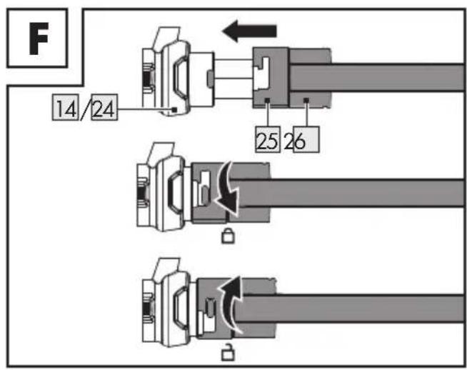
Connecting the vacuum hose
(Fig. E, F, G)

WARNING!

Always wear a dust mask when sanding. Using this product generates a large amount of dust. Harmful dust may be generated when sanding surfaces coated with lead-based paint.
NOTES
Attach an external dust extraction unit (e.g. vacuum cleaner) to the hose adaptor 2930 (at the end of the vacuum hose 28). In this way, you protect yourself as well as persons in the vicinity from dust and you keep the workplace clean.
You may connect the vacuum hose 28 to the connector 14 on the main handle 20 or to the connector 24 on the rear handle 23.
- Insert the hose coupler 26 into the connector 14/24, until it is fully engaged.
■ Locking: Rotate the lock collar25 counterclockwise.
■ Unlocking: Rotate the lock collar25 clockwise.
NOTE
The hose stand ^27 protects the vacuum hose ^28 from excessive bending, when you place the product on a floor in an upright position.
● Changing the hose adaptor
(Fig. H, I)
NOTES
The hose adaptor ^29 with an outer diameter of 47 mm is pre-installed on the vacuum hose ^28 . This adaptor can be directly connected to an industrial vacuum cleaner without using its extraction hose.
Connecting the extraction hose of your vacuum cleaner to the product: Attach the hose adaptor 30 with an outer diameter of 39 mm to the vacuum hose 28.
- Removing: Use the slotted screwdriver 32 to press down one of the locking clips on the dual clip lock ring 36. When the locking clip is fully pressed down, pull out the dual clip lock ring from the hose adaptor 29. The sealing ring 35 must be completely separated.
- Attaching: Insert the sealing ring 35 into the hose adaptor 30.
Align the holes on the hose adaptor with the locking clips on the dual clip lock ring 36. Press down one of the locking clips by hand. Insert the dual clip lock ring into the hose adaptor. Rotate the hose adaptor by 180° and repeat the same steps on the opposite side. Both locking clips must snap into the holes on the hose adaptor.
- Selecting sanding paper
If you need to purchase additional sanding paper, select sanding paper with following characteristics:
- Diameter (∅): 225 mm
- Hook-and-loop fastener on the back
- Pre-punched holes matching the position of the holes on the sanding pad 2
- Made of aluminium oxide, silicon carbide or other synthetic abrasives
The grit size is printed on the back of the sanding paper. The smaller the number, the coarser the grain.
- Rough sanding: Use a sanding paper with a small number.
■ Smooth finishing: Use a sanding paper with a large number.
In order to obtain best results, start with a coarse grain first. Complete the process with the finest grain possible.
- Attaching and removing sanding paper
(Fig. J)
- Attaching: Align the holes on the sanding paper 33 with the holes on the sanding pad 2. The holes allow the dust to be extracted from the sanding guard 1. Press the sanding paper against the sanding pad. The sanding paper is held in position by the hook-and-loop fastener.
■ Removing: Peel off the edge of the sanding paper 33. Pull the sanding paper off the sanding pad 2.
● Function of the brush edge
(Fig. J)
The brush edge 7 protrudes beyond the sanding pad 2. The brush edge is the first part to touch the surface to be sanded. This allows the sanding pad to be positioned in parallel to the surface before the sanding paper 33 touches the surface. This prevents the formation of sickle-shaped recesses caused by the edge of the rotating sanding paper.
The brush edge 7 prevents excessive sand dust escaping from the sanding guard 1.
Before each use: Check the brush edge 7 for damages. If the brush edge is damaged or worn out, have it replaced by a qualified person.
Operation
Connecting to power supply
NOTES
Before you connect the product to the power supply, make sure that the data on the rating plate are identical to the power supply data.
▶ Avoid long supply lines (extension cables).
Do not operate the product in a damp or wet room.
The product may only be operated in suitable rooms (well ventilated).
Connect the power plug15 to a socket-outlet. The product is now ready for use.
- Switching on and off
(Fig. K)
■ Switching on: Press and hold the trigger 19.
Continuous operation: When the trigger 19 is pressed down, press the trigger lock 18.
■ Switching off: Release the trigger 19. If you locked the trigger, press it briefly.
- Adjusting the speed
(Fig. K)
NOTES
Adjust the speed, before you apply the product to the surface.
Use a low speed for rough sanding. Use a high speed for smooth finishing.
■ Increasing speed: Press the + button 17.
■ Reducing speed: Press the – button 16.
NOTE
After you switch off the product, the sanding pad 2 keeps on rotating for a short while. Wait until the sanding pad stops rotating, before you put the product aside.
- Removing and attaching the detachable front guard cover
(Fig. L)
NOTE
You can remove the detachable front guard cover 3, if you want to apply the product closer to the wall/ceiling.
- Removing: Slightly press down the front guard cover lock 4. Pull the detachable front guard cover 3 off the sanding guard 1.
- Attaching: Reattach the detachable front guard cover 3 to the sanding guard 1. The front guard cover lock 4 must click into place.
- Switching the LED working lamp on and off
(Fig. M)
■ Switching on: Press the LED working lamp switch 12 down into the I position.
■ Switching off: Press the LED working lamp switch 12 down into the ○ position.
- Rotating and tilting the motor housing
(Fig. N, O)
NOTE
By rotating and tilting the motor housing 5 you can maximise the accessibility to the working surface. This allows the sanding pad 2 to follow the contours of the working surface.
- You can rotate the motor housing 5 to the left and right by up to 30^ .
- You can tilt the motor housing 5 to the front by up to 30°.
- You can tilt the motor housing 5 to the back by up to 90°.
● Working instructions
■ Select and attach a sanding paper 33.
- Switch on the product and adjust the speed. Wait until the product has reached the set speed.
- Hold the sanding pad 2 parallel to the working surface. Touch the working surface with the brush edge 7.
■ Apply some pressure so that the sanding paper 33 touches the working surface.
■ Move the sanding paper 33 continuously across the working surface. Do not keep the sanding paper on one spot for too long. This may lead to irregular results.
Before switching off: Lift the product from the working surface.
Before putting the product aside: Wait until the sanding pad 2 stops rotating.
Sanding walls
(Fig. P)
■ Always hold the product with 2 hands.
Sanding ceilings
(Fig. Q)
You can turn the product by 180° to reach the surface more easily and comfortably.
After use
- Switch off the product and disconnect it from the mains. Let the product cool down.
- Check, clean and store the product (see "Cleaning and care").
● Cleaning and care

WARNING!

Always switch the product off, disconnect it from the mains and let the product cool down before performing inspection, maintenance and cleaning work!
Cleaning
■ Never allow fluids to get into the product.
The product must always be kept clean, dry and free from oil or grease. Remove dust from it after each use and before storage.
- Regular and proper cleaning will help ensure safe use and prolong the life of the product.
- Clean the product with a dry cloth. Use a soft brush for areas that are hard to reach.
NOTE
Do not use chemical, alkaline, abrasive or other aggressive detergents or disinfectants to clean this product. These detergents and disinfectants might be harmful to the product's surfaces.
Maintenance
Before and after each use, check the product and accessories (e.g. sanding paper) for wear and damage. If required, exchange them for new ones as described in this instruction manual. Observe the technical requirements (see "Technical data").
Replacing the sanding pad
(Fig. R)
WARNING!
Do not use accessories not recommended by Parkside. Using an incompatible sanding pad may result in personal injury or property damage.
- Hold the sanding pad 2 firmly.
Use the hex key 31 to loosen the screw 37 in a counter-clockwise direction.
■ Remove the old sanding pad 2.
Align the centre hole 39 of the new sanding pad with the spindle 40.
Place the washer 38 on the thread of the screw 37.
Use the hex key 31 to fasten the screw 37 in clockwise direction.
Replacing the carbon brushes
(Fig. S)
WARNING!
Always replace both carbon brushes at the same time.
Do not use accessories not recommended by Parkside. Using incompatible carbon brushes may result in electric shock, personal injury or property damage.
Use the slotted screwdriver 32 to loosen the carbon brush holder cap 6 in a counterclockwise direction.
■ Remove the carbon brush holder cap6. The spring of the carbon brush comes out.
■ Remove the carbon brush.
- Insert the spare carbon brush ^34 into the carbon brush holder.
Gently compress the spring of the carbon brush 34 using the carbon brush holder cap 6 until the spring is completely pushed inside.
Use the slotted screwdriver 32 to fasten the carbon brush holder cap 6 in clockwise direction.
- Repeat for the second carbon brush34 on the other side.
Repair
This product does not contain any parts that can be repaired by the user. Contact an authorised service centre or a similarly qualified person to have it checked and repaired.
⚠ WARNING! RISK OF INJURY!
If the power cord is damaged, it must be replaced by the manufacturer, its service agent or similarly qualified persons in order to avoid a hazard.
Storage
- Switch off the product and disconnect it from the mains. Let the product cool down.
■ Clean the product as described before.
■ Store the product and its accessories in a dark, dry, frost-free, well-ventilated place.
Always store the product in a place that is inaccessible to children. The ideal long term storage (longer than 3 months) temperature is between +10 and +30 °C with a relative humidity of max. 60 %.
Transportation
- Switch off the product and disconnect it from the mains. Let the product cool down.
- Protect the product from any heavy impact or strong vibrations which may occur during transportation in vehicles.
- Secure the product to prevent it from slipping or falling over.
Troubleshooting
Problem Possible cause Solution
| Product does not work. Power supply interrupted. Check the socket-outlet by connecting another electric appliance. | ||
| Power cord or power plug 15 defective. | Have the product repaired by a qualified specialist. | |
| Carbon brushes 34 worn out. | Replace the carbon brushes 34 (see “Maintenance”). | |
| Other electrical defect. Have the product repaired by a qualified specialist. | ||
| Product does not operate with full power. | Extension cord too long and/or cross-section too small. | Use an extension cord with permissible length and/or adequate cross-section. |
| Voltage of the power supply (e.g. generator) too low. | Connect the product to an appropriate power supply. | |
Poor performance. Sandpaper worn out. Replace the sandpaper.
| Sanding pad 2 worn out. | Have the sanding pad replaced by a qualified specialist. | |
| Extensive dust formation. | Brush edge 7 worn out. | Have the brush edge replaced by a qualified specialist. |
| External dust extraction unit not connected or switched off. | Connect or switch on external dust extraction unit. |
● Disposal
The packaging is made entirely of recyclable materials, which you may dispose of at local recycling facilities.

Observe the marking of the packaging materials for waste separation, which are marked with abbreviations (a) and numbers (b) with following meaning: 1-7: plastics / 20-22: paper and fibreboard / 80-98: composite materials.

The product and packaging materials are recyclable, dispose of it separately for better waste treatment. The Triman logo is valid in France only.

Contact your local refuse disposal authority for more details of how to dispose of your worn-out product.

To help protect the environment, please dispose of the product properly when it has reached the end of its useful life and not in the household waste. Information on collection points and their opening hours can be obtained from your local authority.
Warranty
The product has been manufactured to strict quality guidelines and meticulously examined before delivery. In the event of product defects you have legal rights against the retailer of this product. Your legal rights are not limited in any way by our warranty detailed below.
The warranty for this product is 3 years from the date of purchase. The warranty period begins on the date of purchase. Please keep the original sales receipt in a safe location. This document is required as your proof of purchase.
Should this product show any fault in materials or manufacture within 3 years from the date of purchase, we will repair or replace it – at our choice – free of charge to you. This warranty becomes void if the product has been damaged, or used or maintained improperly.
The warranty applies to defects in material or manufacture. This warranty does not cover product parts subject to normal wear, thus possibly considered consumables (e.g. batteries) or for damage to fragile parts, e.g. switches, rechargeable batteries or glass parts.
● Warranty claim procedure
To ensure quick processing of your case, please observe the following instructions:
Please have the till receipt and the item number (IAN 380856_2110) available as proof of purchase.
You will find the item number on the rating plate, an engraving, on the front page of the instructions for use (bottom left), or as a sticker on the rear or bottom of the product.
If functional or other defects occur, please contact the service department listed either by telephone or by e-mail.
You can return a defective product to us free of charge to the service address that will be provided to you. Ensure that you enclose the proof of purchase (till receipt) and information about what the defect is and when it occurred.
Service
GB Service Great Britain
Tel.: 08000569216
E-Mail: owim@lidl.co.uk
IE Service Ireland
Tel.: 1800 200736
E-Mail: owim@lidl.ie
CE
● EC declaration of conformity
EC DECLARATION OF CONFORMITY
| IAN: | 380856_2110 |
| Product identification: | PARKSIDE Drywall Sander |
| Model Number: | HG07574 |
The object of the declaration described above is in conformity with the relevant Union harmonisation legislation:
| Directive 2006/42/EC |
| Directive 2014/30/EU |
| Directive 2011/65/EU |
References to the relevant harmonised standards used or references to the other technical specifications in relation to which conformity is declared:
| N° / Parts |
| Directive 2006/42/EC |
| EN 60745-1:2009/A11:201C |
| EN 60745-2-3:2011/A13:2015 |
| Directive 2014/30/EU |
| EN 55014-1:2017/A11:202C |
| EN 55014-2:2015 |
| EN 61000-3-2:2014 |
| EN IEC 61000-3-2:2019 |
| EN 61000-3-3:2013 |
| EN 61000-3-3:2013/A1:2015 |
The object of the declaration described above is in conformity with Directive 2011/65/EU of the European Parliament and of the Council of 8 June 2011 on the restriction of the use of certain hazardous substances in electrical and electronic equipment:
| N° / Parts |
| Directive 2011/65/EU |
| EN IEC 63000:2018 |
Keeper of the technical documentation: OWIM GmbH & Co.KG
Signed for and on behalf:
This declaration of conformity is issued under the sole responsibility of the manufacturer.
Original declaration of conformity
| Neckarsulm | 16.02.2022 | ||
| Place | Date | Benjamin SteebManaging Director | ppa.Jeys BuchheimAuthorised Signatory |
DÉCLARATION DE CONFORMITÉ CE
IAN: 380856_2110
WAARSCHUWING! RISICO OP LETSEL!

WAARSCHUWING! RISICO OP LETSEL!
Authorised Signatory
NL
DEKLARACJA ZGODNOŚCI WE
IAN: 380856_2110
Directive 2006/42/EC
Directive 2014/30/EU
Directive 2011/65/EU
Directive 2006/42/EC
EN 60745-1:2009/A11:201C
EN 60745-2-3:2011/A13:2015
Directive 2014/30/EU
EN 55014-1:2017/A11:202C
EN 55014-2:2015
EN 61000-3-2:2014
EN IEC 61000-3-2:2019
EN 61000-3-3:2013
EN 61000-3-3:2013/A1:2019
Authorised Signatory
PL
Authorised Signatory
CZ
Authorised Signatory
SK
Benjamin Steeb Managing Director
ppa. Budha ppa.Jefns Buchheim
Authorised Signatory
ES
text_image
Neckarsulm 16.02.2022 Sted Dato Benjamin Steeb Ppa Jehs Buchheim Managing Director Authorised SignatoryDK
Authorised Signatory
IT
Directive 2006/42/EC
Directive 2014/30/EU
Directive 2011/65/EU
Negotovost K_pA : 3 dB
Pooblaščeni serviser:
OWIM GmbH & Co. KG
Stiftsbergstraße 1
74167 Neckarsulm
NEMČIJA
Authorised Signatory
SI
OWIM GmbH & Co. KG
Stiftsbergstraße 1
74167 Neckarsulm
GERMANY
Model No.: HG07574
Version: 05/2022
IAN 380856_2110
8=