
PTK 2000 B2 - Sander PARKSIDE - Free user manual and instructions
Find the device manual for free PTK 2000 B2 PARKSIDE in PDF.


| Product type | Table saw |
| Brand | Parkside |
| Model | PTK 2000 B2 |
| Power supply | 230 V~, 50 Hz |
| Power | 2000 W |
| No-load speed | 4800 min-1 |
| Blade diameter | 254 mm |
| Blade bore | 30 mm |
| Blade thickness | 2.8 mm |
| Number of teeth (supplied) | 24 and 48 |
| Table dimensions | 630 x 445 mm |
| Table extension (left/right) | 620 x 250 mm |
| Table extension (rear) | 435 x 320 mm |
| Max. cutting height at 90° | 73 mm |
| Max. cutting height at 45° | 63 mm |
| Cutting angle range | 0° to 45° (left) |
| Weight (with accessories) | approx. 29.5 kg |
| Protection class | I |
| Protection type | IP20 |
| Laser | Category 2, 650 nm, < 1 mW |
| Laser power supply | 2 AAA batteries 1.5 V |
| Suction connection diameter | 34 mm |
| Included accessories | Parallel stop, cross stop, guide, push stick, blade guard, riving knife, etc. |
| Maintenance and cleaning | Clean regularly, oil rotating parts, replace blade if worn |
| Safety | Blade guard, riving knife, emergency stop, guide laser |
| Spare parts available | Yes, via after-sales service (references in manual) |
Frequently Asked Questions - PTK 2000 B2 PARKSIDE
User questions about PTK 2000 B2 PARKSIDE
0 question about this device. Answer the ones you know or ask your own.
Ask a new question about this device
Download the instructions for your Sander in PDF format for free! Find your manual PTK 2000 B2 - PARKSIDE and take your electronic device back in hand. On this page are published all the documents necessary for the use of your device. PTK 2000 B2 by PARKSIDE.
USER MANUAL PTK 2000 B2 PARKSIDE
TISCHKREISSÄGE / TABLE SAW / SCIE CIRCULAIRE SUR TABLE PTK 2000 B2
DE AT CH
TISCHKREISSÄGE
Translation of the original instructions
NL BE
TAFELCIRKELZAAG
Before reading, unfold the page containing the illustrations and familiarise yourself with all functions of the device.
FR BE
natural_image
Close-up of a green electronic device with a black ventilation grille and red arrows indicating force or adjustment (no text or symbols)






Inhalt
Einleitung 6
- Gabelschlüssel SW 8/10
- Gabelschlüssel SW 22
Attention! - laser radiation Do not stare into beam!
class 2 laser product
laser specification according to EN 60825-1:2007
= 650 ~nm
P_0<1mW
Extent of the delivery 33
Overview 34
Functional description 35
Technical data 35
Safety Instructions 35
Symbol and icons 35
Symbols on the appliance 35
Assembly 43
Mounting of the Frame 43
Mounting the table width and length extension 44
Mounting the Suction Adapter ..... 44
Mounting the Riving Knife 44
Mounting/dismounting the Saw Blade Guard 45
Replacing the Table Insert 45
Adjusting/mounting the Riving Knife . 45
Attaching/changing the Saw Blade .. 46
Before putting into operation ..... 46
Operation 46
Switching on and off 46
Adjusting the Cutting Depth 47
Angle Adjustment 47
Working with the Parallel Stop ..... 47
Adjusting the Stop Height 47
Turning the Stop Rail 47
Adjusting the Cutting Width 47
Adjusting the Stop Length 48
Adjusting the Parallel Stop 48
Transverse stop 48
Adjusting the Scale of the Transverse Stop 49
Using the Laser 49
Adjusting the Laser 49
Operation 49
Performing Longitudinal Cuts 50
Cutting narrow Workpieces 50
Cutting very narrow Workpieces ..... 50
Performing Bevel Cuts 51
Performing Transverse Cuts 51
Cutting Chipboard 51
Transport 51
Cleaning and Servicing 52
Cleaning 52
Storage.... 52
Waste disposal and environment protection 52
Spare parts/accessories 53
Guarantee 54
Trouble Shooting 56
Service-Center 57
Importeur 57
Translation of the original EC declaration of conformity ..... 194
Introduction
Congratulations on the purchase of your new device. With it, you have chosen a high quality product.
During production, this equipment has been checked for quality and subjected to a final inspection. The functionality of your equipment is therefore guaranteed.

The operating instructions constitute part of this product. They contain important information on safety, use and disposal.
Before using the product, familiarise yourself with all of the operating and safety instructions. Use the product only as described and for the applications specified.
Keep this manual safely and in the event that the product is passed on, hand over all documents to the third party.
Intended purpose
The table circular saw is used for cutting all types of wood lengthwise and crosswise (only with the transverse stop), depending on the machine size. All types of round timbers must not be cut with it. The machine may be used only for its prescribed purpose.
Any other use beyond that is considered to be not in accordance with the designated purpose. The user/operator is liable for all types of resulting damage or injury and not the manufacturer.
The only saw blades which may be used are those which are suitable for the machine (HM or CV saw blades).
The use of any type of HSS saw blades and cutting discs is prohibited. Use in accordance with the designated purpose is also deemed to include observance of the safety instructions, as well as the assembly and operating instructions in the operating manual. Individuals who operate and maintain the machine must be familiar with it and must have been instructed in possible hazards. Moreover, the latest accident prevention regulations must be strictly observed. Other general rules in the fields of occupational health and safety technology must be complied with.
Caution!
When using equipment, certain safety precautions must be complied with in order to avoid injuries and damage. You should therefore read these operating instructions / safety instructions carefully. Keep these in a safe place so that the information is available to you at all times. Should you give the device to anyone else, please give them these operating instructions / safety instructions as well. We assume no liability for accidents or damage caused by failure to observe these instructions or the safety instructions. Changes to the machine will cause the manufacturer's liability with respect to any resulting damage to be completely excluded. Even when the device is used in accordance with the designated purpose, it is nevertheless not possible to completely eliminate certain residual risk factors. Due to the design and structure of the machine, the following risks may occur:
- Touching the saw blade in the area of the saw which is not covered;
- Reaching into the running saw blade (cuts)
- Kickback of workpieces and workpiece parts.
- Saw blade breaks.
- Ejection of faulty hard metal parts of the saw blade.
- Hearing damage if the necessary hearing protection is not used.
- Emissions of wood dust which are harmful to the health when used in closed rooms.
Please note that the use of our devices in accordance with the designated purpose does not include commercial, handicraft or industrial applications. We assume no warranty if the device is used in commercial, handicraft or industrial businesses or for equivalent purposes..
General description Extent of the delivery
Carefully unpack the appliance and check that it is complete:
-- Saw table with pre-assembled, carbide-tipped saw blade with 24 teeth
- Carbide-tipped saw blade with 48 teeth
- Blade guard
GBIE
- Suction hose
- Suction adapter with rubber seal
- Riving knife with laser
- Batteries 1.5V AAA (2x)
- Parallel stop
- Stop rail
- Transverse stop
- Table width extender (2x)
- Table length extender
- Push stick
- Legs (4x)
- Cross struts (2x)
- Longitudinal struts (2x)
- Central struts, short (2x)
- Central struts, long (2x)
- Rubber feet (4x)
- Stand brackets (2x)
- Table supports, short (4x)
- Table supports, long (2x)
- Translation of the original instructions for use
Mounting Material
-
Bag A for legs and central struts: Hexagonal bolt with mounted washer/spring washer (f), 8 pieces;
Hexagonal bolt (g) = lock washer (b), 2x washer (a), nut (c), 4 pieces;
Round head bolt, M6 x 12 (e) washer (a), lock washer (b), nut (c), 8 pieces each -
Bag B for stand bracket and upper struts: Round head bolt, M6 x 12 (d) = washer (a), lock washer (b), nut (c), 20 pieces each
- Bag C for table length/width extension: Hexagonal bolt with mounted washer/spring washer (f), 12 pieces;
Hexagonal bolt (g) = lock washer (b), 2x washer (a), nut (c), 6 pieces
Tools
- Jaw spanner SW 22
- Hexagon socket wrench HX 6
- Jaw spanner SW 8/10
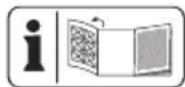
The illustrations are on the fold-out pages.
Overview
1 1 Saw table ade guard
3 Suction hose
4 Riving knife
5 Saw blade
6 Table insert
7 Table width extender
8 Transverse stop
9 Locking handle
10 Base
11 On/off switch
12 Handwheel
13 Guide rail
14 Parallel stop
15 Table length extender
16 Suction adapter with Rubber seal
17 Push stick
18 Legs
19 Cross struts
20 Longitudinal struts
21 Central struts, short
22 Central struts, long
23 Rubber feet (4x)
24 Stand brackets (2x)
25 Table brackets, short
26 Table brackets, long
27 Bolt with wing nut
28 Slot in the riving knife
29 Countersunk screws of the table insert
30 Fixing bolts of the riving knife
31 Cam lever
32 Groove
33 Knurled screw
34 Laser
35 Laser switch
36 Screws for battery compartment
37 Battery cover
38 Attachment points
39 Stop rail
Functional description
The table circular saw is used for cutting all types of wood lengthwise and crosswise (only with the transverse stop), depending on the machine size. All types of round timbers must not be cut with it.
Technical data
Bench circular saw....PTK 2000 B2
AC motor 230 V\~ 50Hz
Power 2000 Watt
Operating mode ....S6 40%*
Safety class .... I
Protection category.....IP20
Idling speed 4800 min ^1
Carbide saw blade ∅ 254 x ∅ 30 x 2,8 mm
Number of teeth 24 / 48
Thickness riving knife 2,5 mm
min. Workpiece size WxLxH 10x50x1 mm
Table size 630 x 445 mm
Table width extender
left/right 620 x 250 mm
Table length extender rear ..435 x 320 mm
Cutting height max. 90° ..... 73 mm
Cutting height max. 45° ..... 63 mm
Height adjustment 0 - 73 mm
Saw blade, swivelling 0 - 45°
Extraction connection .... 0 34 mm
Weight (including accessories), ....approx 29,5 kg
Laser class 2
Laser wavelength 650 nm
* Operating mode S6 40%: Continuous operation with intermittent load (cycle time 10 min). In order not to heat the motor more than permitted, the motor may only be operated for 40% of the cycle time with the stated nominal power and must then continue running for 60% of the cycle time without a load.
Technical and optical changes may be undertaken in the course of further development without notice. All dimensions, references and information in this instruction manual are therefore not guaranteed. Legal claims made on the basis of the instruction manual can therefore not be considered as valid.
Safety instructions
Ensure that the safety instructions are observed when operating the appliance.
Symbols and icons
Symbols on the appliance:

Carefully read these Operating Instructions.

Wear eye protection.

Wear ear protection.

Wear breathing protection.
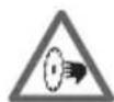
Caution - Risk of injury. Never reach into the running blade.
GBIE

Do not expose the unit to rain. The device must not be wet, nor should it be operated in a moist environment.

Caution - a damaged blade must not be used under any circumstances. Replace the saw blade immediately.

Caution! - Laser radiation. Do not look into the beam.
Laser class 2


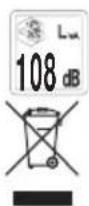
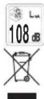
Information of the acoustic power level L_WA in dB.
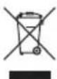
Electrical appliances must not be disposed of with the domestic waste.
Symbols in the manual

Warning symbols with information on damage and injury prevention.

Instruction symbols (the instruction is explained at the place of the exclamation mark) with information on preventing damage.

Help symbols with information on improving tool handling.
Safe operation
1 Keep work area clear.
- Cluttered areas and benches invite injuries.
2 Consider work area environment.
- Do not expose tools to rain.
- Do not use tools in damp or wet locations.
- Keep work area well lit.
- Do not use tools in the presence of flammable liquids or gases.
3 Guard against electric shock
- Avoid body contact with earthed or grounded surfaces (e.g. pipes, radiators, ranges, refrigerators).
4 Keep other persons away!
- Do not let persons, especially children, not involved in the work touch the tool or the extension cord and keep them away from the work area.
5 Store idle tools
- When not in use, tools should be stored in a dry locked-up place, out of the reach of children.
6 Do not force the tool.
- It will do the job better and safer at the rate for which it was intended.
7 Use the right tool.
- Do not force small tools to do the job of a heavy tool.
- Do not use the power tool for such purposes for which it is not intended. Use for example no circular saws to cut tree branches or logs.
- Do not use the electric tool to the firewood saws.
8 Dress properly.
- Do not wear loose clothing or jewellery, they can be caught in moving parts.
- Non-skid footwear is recommended when working outdoors.
- Wear protective hair covering to contain long hair.
9 Use protective equipment.
- Use safety glasses.
- Use face or dust mask if working operations create dust.
10 Connect dust extraction equipment
- If the tool is provided for the connection of dust extraction and collecting equipment, ensure these are connected and properly used.
- Indoor operation is permitted only with a suitable extraction system.
11 Do not abuse the cord.
- Never yank the cord do disconnect it from the socket. Keep the cord away from heat, oil and sham edges.
12 Secure work.
- For long workpieces, an additional supporting surface (table, trestles, etc.) is required in order to prevent tipping of the machine.
- Always press the workpiece firmly against the working surface and stop in order to prevent wobbling or twisting of the workpiece.
13 Do not overreach
- Keep proper footing and balance at all times.
- Avoid awkward hand positions in which one or both hands could touch the saw blade as the result of a sudden slip.
14 Maintain tools with care
- Keep cutting tools sharp and clean for better and safer performance.
– Follow instruction for lubricating and changing accessories.
- Inspect tool cords periodically and if damaged have them repaired by an authorized service facility.
- Inspect extension cords periodically and replace if damaged.
- Keep handles dry, clean and free from oil and grease.
15 Disconnect tools.
- Never remove loose splinters, chips or jammed pieces of wood when the saw blade is running.
- When the electric tool is not in use, before maintenance and when changing tools such as the saw blade, drill bit, milling cutter.
16 Remove adjusting keys and wrenches
- Form the habit of checking to see that keys and adjusting wrenches are removed from the tool before turning it on.
17 Avoid unintentional starting.
- Ensure switch is in "off" position when plugging in.
18 Use outdoor extension leads.
- When the tool is used outdoors, use only extension cords intended for outdoor use and so marked.
- Use the cable drum only in the unrolled state.
19 Stay alert.
Watch what you are doing, use common sense and do not operate the tool when you are tired.
20 Check damaged parts.
- Before further use of tool, it should
be carefully checked to determine that it will operate properly and perform its intended function.
- Check whether the moving parts are working properly and are not becoming jammed or whether parts are damaged. All parts must be correctly fitted and satisfy all conditions to ensure the proper operation of the power tool.
- The movable guard must not be clamped when it is open.
- A guard or other part that is damaged should be properly repaired or replaced by an authorized service centre unless otherwise indicated in this instruction manual.
- Have defective switches replaced by an authorized service centre.
- Do not use any faulty or damaged connection cables.
- Do not use the tool if the switch does not turn it on and off.
21 Warning!
- The use of any accessory or attachment other than one recommended in this instruction manual may present a risk of personal injury.
22 Have your tool repaired by a qualified person.
- This electric tool complies with the relevant safety rules. Repairs should only be carried out by qualified persons using original spare parts, otherwise this may result in considerable danger to the user.
ADDITIONAL SAFETY INSTRUCTIONS
1 Safety Precautions
- Warning! Do not use damaged, cracked or deformed saw blades.
- Replace a worn table insert. Regrinding is not allowed.
- Only use saw blades recommended by the manufacturer which conform to EN 847-1. Warning! When changing the saw blade ensure that the cutting width is not smaller and the main blade thickness of the saw blade not greater than the thickness of the riving knife!
- Make sure that a saw blade is selected which is appropriate for the material to be cut.
- Wear appropriate personal protective equipment. This includes: Hearing protection to reduce the risk of becoming hard of hearing, breathing respirator to reduce the risk of inhaling hazardous dust.
- Wear gloves when handling saw blades and rough materials.
- Whenever practicable, saw blades should be carried in a container.
- Wear safety goggles. Any splinters, chips and dusts which are ejected from the device when it is in operation may cause sight loss.
- Connect the power tool to a dust collection device when sawing wood. Among other things, the emission of dust is affected by the type of material to be machined, the importance of local deposition (capture or source) and the correct setting of hoods/deflector plates/guide mechanisms.
- Do not use any saw blades made of high-alloy high-speed steel (HSS).
- Always store the push stick or push block in its holder on the power tool when not in use.
2 Maintenance and Servicing
- Always remove the mains plug when carrying out any adjustments or maintenance work.
- The cause of the noise is influenced by various factors, including the properties of the blades, the condition of the saw blade and power tool. If possible, use saw blades that are designed to reduce the noise level, service the power tool and tool attachments regularly and repair them if necessary to reduce noise.
- Report any faults to the power tool, safety devices or the tool attachment as soon as they are discovered to the person responsible for safety.
3 Safe Working
- Use the push stick or the handle with push block to pass the workpiece safely past the saw blade.
- Make sure that the riving knife is always used and that this is correctly adjusted.
- Use the upper blade guard and adjust it correctly.
- Use only saw blades whose maximum speed is not lower than the maximum spindle speed of the tool being used and which are suitable for the material to be cut.
- Do not create any rebates or grooves unless a suitable protective device, such as a tunnel guard, is attached above the saw table.
- Circular saws must not be used for slotting (cutting grooves which end in the workpiece).
- When transporting the power tool, use only the transport devices
supplied. Never use the guards for handling or transporting the tool.
- During transport, make sure that the top part of the saw blade is covered, for example with the guard.
- Ensure that the only spacer washers and spindle rings which are used are suitable for the purpose stated by the manufacturer.
- The floor around the machine must be flat, clean and free of loose particles such as chips and cutting residues.
- Working position always to the side of the saw blade.
- Do not remove any cutting residues or other parts of the workpiece from the cutting area for as long as the machine is running and the sawing unit is not yet in the rest position.
- Secure long workpieces against tilting at the end of the cutting operation (e.g. unwinding stand or roller stand).
- Caution! long workpieces against tilting at the end of the cutting operation (e.g. unwinding stand or roller stand).
- Caution! Never remove any loose splinters, chips or jammed pieces of wood when the saw blade is still running.
- Always switch off the machine and remove the plug before repairing any faults or removing jammed pieces of wood.
- Always switch off the motor and remove the plug before carrying out any conversions or adjustment, measurement and cleaning work.
- Before switching on, check that the spanners and adjustment tools have been removed.
GBIE
Warning! During operation, this power tool produces an electromagnetic field. Under certain circumstances, this field may negatively affect active or passive medical implants. In order to reduce the danger of serious or fatal injuries, we recommend that individuals who wear medical implants should consult their doctor and the manufacturer of the implant before operating the power tool.
SAFETY INSTRUCTIONS FOR HANDLING SAW BLADES
1 Only use tools which you know how to handle.
2 Pay attention to the maximum speed. The maximum speed stated on the tool being used must not be exceeded. Keep within the speed range if one is specified.
3 Note the direction of rotation of the motor and saw blade.
4 Circular saw blades with cracks in them must be taken out of service (repair is not permitted).
5 Tools with visible cracks must not be used.
6 Tools must be cleaned regularly.
7 Handle the tools used with care. It is best to store these in their original packaging or special containers. Always wear protective gloves to improve your grip and further reduce the risk of injury.
8 Before using any of the tools, ensure that all protective devices are correctly attached.
9 Before use, ensure that all of the tools used by you fulfil the technical requirements of this power tool and are properly attached.
10 The saw blade supplied should only be used for sawing wood and never for working metal.
Assembly and Attachment of Tools and Tool Parts
a) Tools and tool bodies must be tightened in such a way that they cannot become loose during operation.
b) Attachment bolts and nuts are to be tightened to the torques specified by the manufacturer using appropriate spanners etc.
c) Extending a spanner or tightening with the help of hammer blows is not permitted.
d) The tightening surfaces must be cleaned to remove any dirt, grease, oil and water.
e) Tensioning bolts must be tightened in accordance with the manufacturer's instructions.
f) In order to adjust the borehole diameter of circular saw blades to the spindle diameter of the machine, only firmly inserted rings, e.g. rings which have been pressed into place or which are held in place by means of an adhesive bond, may be used. The use of loose rings is not permitted.
g) Ensure that fixed reducing rings are positioned parallel to one another.
Safety Instructions for Handling the Laser
- Caution: Laser radiation - Do not look into the beam - Laser class 2
Safety Instructions for Handling Batteries
1 Ensure at all times that the batteries are inserted with the correct polarity (+ and -), as shown on the battery itself.
2 Do not short-circuit the batteries.
3 Do not charge up rechargeable batteries.
4 Do not overcharge the battery!
5 Do not mix old and new batteries or batteries of a different type or from different manufacturers! Replace all batteries of a set at the same time.
6 Remove used batteries immediately out of the device and dispose of them correctly!
7 Do not heat the batteries!
8 Do not carry out any welding or soldering work directly to the batteries!
9 Do not take the batteries apart!
10 Do not deform the batteries!
11 Do not throw the batteries into the fire!
12 Store the batteries out of the reach of children.
13 Do not allow children to replace the batteries without supervision!
14 Do not store the batteries close to a fire, cookers or other sources of heat. Do not place the battery in direct sunlight and do not use or store it in motor vehicles in hot weather.
15 Store used batteries in the original packaging and keep them away from metal objects. Do not mix (up) unpacked batteries! Otherwise this may cause the battery to short-circuit, resulting in damage, burns or even the danger of fire.
16 Remove batteries from the device if this is not going to be used for a prolonged period, unless it is to be used in emergencies!
17 NEVER touch batteries which have leaked without appropriate protection. If the leaked liquid comes into contact with the skin, you should rinse off this area of the skin immediately under running water. Make sure at all events that your eyes and mouth do not come into contact with the liquid. If they do, seek medical advice immediately.
18 Clean the battery contacts and the equivalent contacts in the device before inserting the batteries.
Residual Risks
This power tool has been constructed in accordance with the latest technology and the generally recognised safety regulations. Nevertheless, it is possible that individual residual risks may occur during operation.
- Electrical hazard if improper electrical connection cables are used.
- In addition, concealed residual risks may be present in spite of all the precautions that have been taken.
- Residual risks can be minimised by observing the „Safety instructions“ and „Use in accordance with the designated purpose“, as well as the operating instructions.
- Do not put any unnecessary stresses on the machine: excessive pressure during sawing will quickly damage the saw blade. This may result in a
GBIE
reduction in the performance of the machine, as well as a reduction in the cutting accuracy.
- Avoid switching the machine on by accident: when inserting the plug into the socket, the power button must not be pressed.
- Use the tool which is recommended in this manual. This will ensure the optimal performance of your saw.
- Keep your hands away from the working area when the machine is in operation.
- Before you carry out any adjustments or servicing work, turn the device off and remove the mains plug.
5. Electrical Connection
The installed electric motor is connected ready for operation. The connection complies with the relevant VDE and DIN regulations. The customer's network connection and any extension cable used must comply with these regulations.
- The product meets the requirements of EN 61000-3-11 and is subject to special connection conditions. This means that its use at freely selectable connection points is not permitted.
- If the network conditions are unfavourable, the device may result in temporary voltage fluctuations.
- The maximum permitted mains impedance at the electrical connection point of 0.107 ohm must not be exceeded.
- As the user, you must ensure – in consultation with your electricity supply company if necessary – that the continuous current carrying capacity
of the network at the connection point to the public mains is sufficient for the connection of the product.
Important Instructions
If the motor is overloaded, it switches itself off automatically. After cooling down (times vary), the motor can be switched on again.
Faulty Electrical
Connection Cable
Insulation damage often occurs to electrical connection cables.
The causes of this may be as follows:
- Pressure points if connection cables are routed through windows or door gaps.
- Kinks caused by improper attachment or routing of the connection cable.
- Cut surfaces caused by vehicles driving over the connection cable.
• Insulation damage caused by tearing out of the wall socket. - Cracks resulting from the insulation becoming old.
Such faulty electrical connections must not be used and may endanger life due to the damage to the insulation.
Electrical connection cables should be checked regularly for damage. Ensure that during such checks, the connection cable is not connected to the mains.
Electrical connection cables must comply with the relevant VDE and DIN regulations. Only use connection cables with the marking H05VV-F.
It is stipulated by law that the type of connection cable must be printed on it.
Alternating Current Motor
• The mains voltage must be 230 V\~.
- Extension cables up to 25 m in length must have a cross-section of 2.5 mm ^2 .
Connections and repairs to the electrical equipment may only be performed by a qualified electrician. If you have any queries, please provide the following information:
• Current type of the engine
• Data from the machine type plate
• Data from the motor type plate
Assembly
Assembly, Replacement of Parts and Adjustments
Caution! The mains plug must be removed before all servicing, retooling and assembly work.
Place all of the parts supplied on a flat surface. Form groups of the parts which are similar.
Note: If connections are secured with a bolt (round head/or hexagonal), hexagonal nuts and a washer, the washer must be placed under the nut.
Insert the bolts from the outside to the inside in each case, securing the connections with nuts from the inside.
Note: Tighten the nuts and bolts during assembly only to the extent that they cannot fall off.
If you tighten the nuts and bolts any further before final assembly, it is not possible for final assembly to be carried out.
Additional tool required:
- Phillips screwdriver
Mounting of the Frame
Abb.4-10
- Turn the table circular saw over and place it on the floor.
- Unscrew the four mounted rubber feet with a Phillips screwdriver (Figure 5).
- Screw the four legs (18) with the hexagon bolts (e) loosely on to the saw (Figure 6). Use the jaw spanner (r) supplied for this.
Caution! 2 of the legs have holes (38) drilled into the rear, into which the stand brackets have to be fixed. (Figures 6 and 10) Ensure that these are attached at the rear of the machine.
-
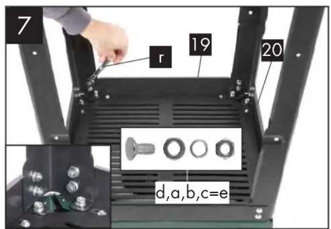
Now take the cross struts (19) (marked A) and longitudinal struts (20) (marked B). Screw these loosely together with the four central struts (21, 22) to the legs. Mounting material: Round head bolts (d), washer (a), spring washer (b) and nuts (c), (Figure 6-8).
-
The round head bolts (d) and nuts (c) should only be loosely tightened. Caution: The longer struts (marked B) must be used at the side. Secure the central struts with the hexagon bolts, as shown in detail in Figure 8.
-
Now attach the rubber feet (23) to the legs (Figure 9).
-
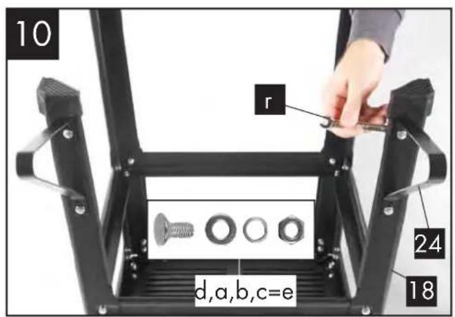
Screw the stand brackets (24) into the rear legs using the drill holes. Mounting material: 2 each: round head bolts (d), shims (a), spring washer (b) and nuts (c), (Figure 10).
Caution! Both stand brackets must be attached to the rear of the machine at attachment points 38!
- Then tighten all of the bolts and nuts of the base.
Mounting the table width and length extension (Figures 11-14)
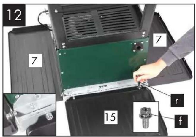
- Loosely tighten the table width extension (7) and table length extension (15) on the saw table using the hexagon bolts (f). (Figure 12).
- Loosely tighten the table supports (25, 26) on the housing of the table circular saw using hexagon bolts (f). In addition, the table supports (25, 26) also have to be loosely tightened to the table width and length extensions. Mounting material: Hexagon bolts (e), washer (a) and nut (c). The short supports (25) are for the table widening extension, the long supports (26) for the length extension, (Figures 13, 14).
- Turn the saw over with the base and place it on the floor.
- Align the table width and length extension flush with the saw table.
- Then tighten all bolts.
Mounting the Suction Adapter
(Figure 15)
- Insert the suction adapter (16) into the opening provided on the rear of the machine. The side outlet is now pointing outwards.
-
The suction adapter has a rubber seal; make sure that this is mounted.
-
The adapter is secured by means of a bayonet lock. Insert the vacuum cleaner adapter (16) as shown in Figure 15 and lock this in place with a quarter turn in a clockwise direction.
Mounting the Riving Knife (Figures 16-19)
Caution! Remove the mains plug! The setting of the saw blade (5) must be checked whenever a blade has been replaced.
- Inserting the batteries (Figure 16):
- Turn the laser on/off switch (35) to the 0 position (laser off).
- Remove the battery compartment cover (37) by loosening the screw (36). Now remove the battery compartment cover (37) by bending at the side.
- Insert the batteries supplied (type AAA), ensuring the correct polarity (see Figure 16).
- Put the battery compartment cover (37) back in position and tighten it with the screw (36). Notes concerning the batteries:
- If you are not going to use the laser for a prolonged period, please remove the batteries from the battery compartment. Otherwise, the leaking of battery fluid might damage the device.
- Do not place the batteries on radiators or expose them for a prolonged period to strong sunlight; temperatures above 50^ could damage the device.
- Adjust the saw blade (5) to a max. cutting depth, move to the 0^ position and lock in place.
-
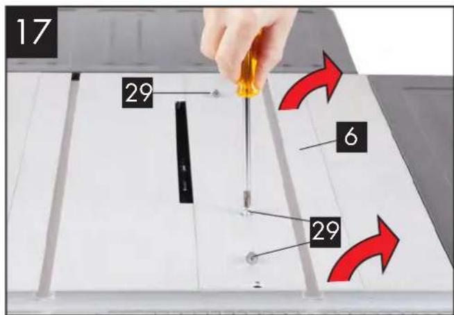
Release the screws (29). Remove the table insert (6) (Figure 17).
-
Release the two attachment bolts (30) and insert the riving knife (4) between the metal plate and the mount (see Figure 18).
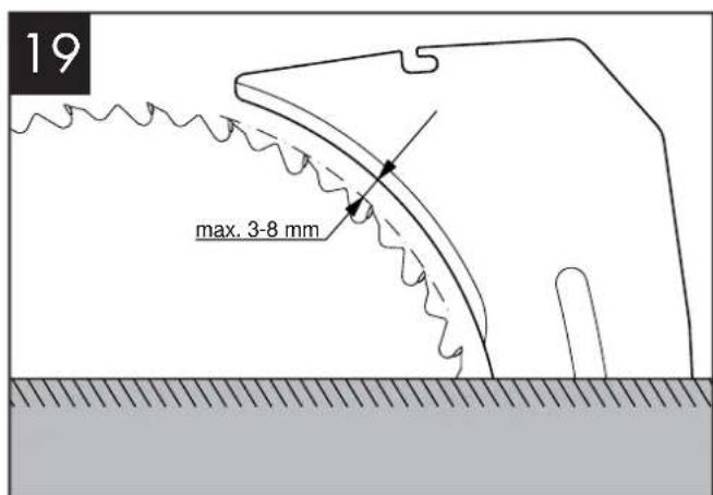
- The distance between the saw blade and riving knife (4) should be between 3 mm and max. 8 mm, (Figure 19).
- Retighten the attachment bolts (30) and mount the table insert (6) (see Figure 17).
Mounting / dismounting the Saw Blade Guard
(Figures 20/21)
- Before initial assembly, the batteries of the laser have to be inserted (see Mounting the Riving Knife 1).
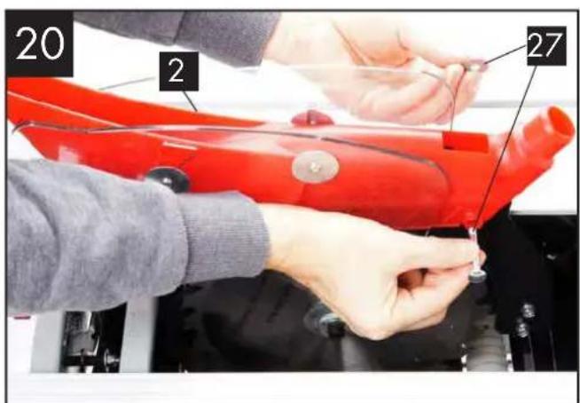
- Dismantle the bolt with wing nut and shim (27) of the saw blade guard (2). Place the saw blade guard (2) from the top onto the riving knife (4).
- Mount the bolt with the wing nut and shim (27) so that the bolt sits firmly in the slot (28).
- Do not overtighten the bolt (27). The saw blade guard must be able to move freely.
- Place the suction hose (3) on the suction adapter (16) and the suction connector of the saw blade guard (2). Connect a suitable woodchip extraction system to the suction adapter (16), (Figure 21).
- Dismantling is carried out in reverse order. Caution! Before you start sawing, the saw blade guard (2) has to be lowered onto the item being sawn.
Replacing the Table Insert (Figures 17 and 22)
- If it is worn or damaged, the table insert (6) has to be replaced, as otherwise there is an increased risk of injury.
- Remove the 3 countersunk screws (29).
- Take out the worn table insert (6).
- The new table insert is mounted in reverse order.
Adjusting / mounting the Riving Knife
(Figures 16-19)
Caution! Remove the mains plug! The setting of the saw blade (5) must be checked whenever a blade has been replaced.
- Adjust the saw blade (5) to the max. cutting depth, move to the 0^ position and lock in place.
- Dismantle the saw blade guard (2)
- Take out the table insert (6).
- Loosen the attachment bolts (30).
- Push the riving knife (4) upwards.
- The distance between the saw blade (5) and riving knife (4) should be max. 8 mm. (Figure 19)
- Retighten the attachment bolts (30) and mount the table insert (6).
- Reattach the saw blade guard (2).
Attaching/changing the Saw Blade
(Figure 22)
- Caution! Remove the mains plug and wear protective gloves.
- Dismantle the saw blade guard (2).
- Remove the table insert (6) by releasing the three countersunk screws (29) (see Figure 17)
- Place the hexagon socket key (s) (HX 6) on the bolt and use the jaw spanner (t) (SW 22) to stop the motor spindle from turning (see Figure 22).
- Caution! Turn the bolt in the direction of rotation of the saw blade.
- Remove the outer flange and take the old saw blade off the inner flange by pulling downwards and diagonally.
- Clean the saw blade flanges carefully with a wire brush before attaching the new saw blade.
- Insert and tighten the new saw blade in reverse order.
Caution! Note the direction of motion; the slope of the cutting edge of the teeth must face the direction of motion, i.e. forwards (see the arrow on the saw blade guard (2).
- Reattach and adjust the table insert (6) and the saw blade guard (2).
- Before you work with the saw again, a check must be carried out to ensure that the protective devices are working properly.
Before putting into operation
- The machine must be set up on a stable surface, i.e. on the base or similar item. For this, use the drill holes which are located in the frame of the machine. For safe use on a work bench, four mounted rubber feet are provided (fig. 5).
- Before the machine is put into operation, all covers and safety devices must be properly attached.
- The saw blade must be able to move freely.
- In the case of wood which has already been worked with, check for foreign bodies such as nails or screws etc.
- Before pressing the on/off switch, make sure that the saw blade is correctly attached and that moving parts are free-running.
- Before connecting the machine, check that the data on the type plate matches those of the mains system.
- The machine must only be connected to a properly installed safety socket which is protected by a fuse of at least 16A.
- If possible, connect the device only to a socket with a residual current circuit breaker (RCCB) with a tripping current of not more than 30 mA.
Operation
Switching on and off (Figure 23)
- The saw can be switched on by pressing the green pushbutton „I“. Before you start sawing, wait until the saw blade has reached its maximum speed.
- In order to switch the saw off again, the red pushbutton „0“ has to be pressed.
Adjusting the Cutting Depth
(Figure 23)
By turning the hand wheel (12) to adjust the height, the saw blade can be set to the desired cutting depth (continuous).
Important: the hand wheel (12) has to be pulled out to adjust the cutting depth. When the hand wheel is pressed in, this adjusts the cutting angle.
- Anticlockwise: increases the cutting depth
- Clockwise: reduces the cutting depth Check the adjustment by means of a test cut.
Angle Adjustment
(Figure 23)
With the table circular saw it is possible to make bevel cuts to the left at an angle of 0^ to 45^ to the stop rail. Before each cut, make sure that no collision is possible between the stop rail (39), cross-cutting gauge (Figure 1, no. 8) and the saw blade (5).
- Release the locking handle (9)
- Set the desired angle on the scale by pressing in and turning the hand wheel (12).
- Lock the locking handle (9) in the desired angular position.
Working with the Parallel Stop
Adjusting the Stop Height
(Figures 24-26)
- The stop rail (39) of the parallel stop (14) has two guide surfaces at different heights.
- Depending on the thickness of the materials to be cut, the stop rail (39) has to be used differently. For thin material (workpiece thickness less than 25 mm), use Figure 24. For thick material (workpiece thickness more than 25 mm), use Figure 26.
Turning the Stop Rail
(Figures 24-26)
- In order to turn the stop rail (39), first of all release the two wing nuts (h).
- Now the stop rail (39) can be pulled off the guide rail (14) and pushed back over this again with the correct guide mechanism.
- Retighten the wing nuts (h).
Adjusting the Cutting Width
(Figures 27-28)
- When wooden pieces are being cut lengthwise, the parallel stop (14) has to be used.
- The parallel stop should be mounted on the right-hand side of the saw blade (5).
- Insert the parallel stop into the side of the guide rail (13) (Figure 28).
GBIE
- On the guide rail for the parallel stop (13) there are 2 scales (j/k). These show the distance between the stop rail (39) and saw blade (5) (Figure 27).
- Select the suitable scale according to whether the stop rail (39) has been turned around for working with thick or thin material:
High stop rail (thick material):
scale (j)
Low stop rail (thin material):
scale (k)
- Adjust the parallel stop (14) to the desired level on the sight glass (l) and fix in place with the cam lever (31).
Adjusting the Stop Length (Figure 29)
- In order to prevent the material being cut from jamming, the stop rail (39) can be moved in the longitudinal direction.
- Rule of thumb: the rear end of the stop abuts on an imaginary line. This begins at about the middle of the saw blade and runs towards the back at an angle of 45^ .
- Adjust the required cutting width.
- Release the wing nuts (h) and push the stop rail (39) forwards until the imaginary 45^ line is touched.
- Retighten the wing nuts (h).
Adjusting the Parallel Stop (Figure 30)
- Caution! Remove the guard.
- Adjust the saw blade (5) to the maximum cutting depth.
- Adjust the parallel stop (14) such that the stop rail (39) touches the saw blade (adjustment for thick material.
- If the parallel stop (14) is not parallel to the saw blade (5), please proceed as follows. Release the screws (m) on the parallel stop until the parallel stop (14) can be aligned to be parallel with the saw blade (5) (Figure 30).
- Retighten the screws (m).
Transverse stop (Figure 31)
- Push the transverse stop (8) into a groove (32) of the saw table.
- Loosen the knurled screw (33).
- Turn the transverse stop (8) until the desired angle is set. The notch on the guide bar shows the angle that has been set.
- Retighten the knurled screw (33).
- When the wood is being cut to size, the transverse stop (8) must be extended with the stop rail (39) of the parallel stop (14) (Figure 31)
- In order to extend the transverse stop (8) with the stop rail (39), the stop rail (39) has to be removed from the parallel stop (14). Now the stop rail has to be mounted as shown in Figure 31; use the star grips (q) for this.
Caution!
- Do not push the stop rail (39) too far in the direction of the saw blade.
- The distance between the stop rail (39) and saw blade (5) should be approximately 2 cm. (Figure 31).
Adjusting the Scale of the Transverse Stop
(Figure 32)
- Create a 90^ stop angle with respect to the saw blade (5).
- Connect the transverse stop (8) to the stop rail (39) of the parallel stop 14) (see also Transverse Stop).
- Loosen the knurled screw (33) of the transverse stop (8).
- Position the transverse stop (13) such that the stop rail is at an angle of 90^ to the saw blade (5). Now align the transverse stop precisely with the help of the 90^ angle to the saw blade and retighten the knurled screw (33).
- Check whether the transverse stop shows exactly 90°. If this is not the case, please proceed as follows:
- Release the two screws (o) with which the scale (p) of the transverse stop (8) is attached to it. Now the scale can be adjusted to the correct position.
- Now retighten the screws (o) (see figure 31).
Using the Laser
(Figures 33-34)
- The laser (34) enables you to carry out precision cuts with your circular saw.
- The laser light is produced by a laser diode supplied by two batteries. The laser light is expanded to form a line and is emitted through the laser exit aperture. You can then use the line as an optical marking for the cutting line of the precision cut. Please note the laser safety information.
-
Insert the batteries
-
Switch on the laser: turn the laser on/off switch (35) to I. When the saw blade guard (2) is mounted, the laser on/off switch (35) is accessible through a recess in the guard (Figure 33). A red laser beam is now projected out of the laser exit aperture. If you guide the laser beam along the cutting line mark while sawing, you will achieve clean cuts.
- Switch the laser off: turn the laser on/off switch (35) to 0. The laser beam goes off. Please always turn the laser off when it is not required in order to save the batteries.
- The laser beam may be blocked by dust deposits and chips. You should therefore remove these particles from the laser exit aperture after every use (with the device switched off).
Adjusting the Laser
(Figure 34)
If the laser (34) no longer shows the correct cutting line, this can be readjusted. To do this, open the screws (z). Adjust the laser with the help of the adjusting screw (y) such that the laser beam impinges on the cutting teeth of the saw blade (5).
Operation
Working Instructions
After each new adjustment, we recommend a trial cut in order to check the set dimensions. After the saw has been switched on, wait until the saw blade has reached its maximum speed before you carry out the cut.
Secure long workpieces against tilting at the end of the cutting process (e.g. unwinding stand etc.)
Caution with incision cutting.
Operate the device only with a suction system. Check and clean the suction channels regularly.
Suitability of the saw blades:
- 24 teeth: soft materials, high chip removal, rough cut image
- 48 teeth: hard materials, lower chip removal, finer cut image
Performing Longitudinal Cuts
(Figure 35)
Here, a workpiece is cut in its longitudinal direction. One edge of the workpiece is pressed against the parallel stop (14) while the flat side lies on the saw table (1). The saw blade guard (2) must always be lowered onto the workpiece. The working position during longitudinal cutting must never be in a straight line with the cutting line.
- Adjust the parallel stop (14) according to the workpiece height and the desired width.
- Switch on the saw.
- Place your hands with the fingers closed together flat on the workpiece and push the workpiece along the parallel stop (14) into the saw blade (5).
- Guide from the side with your left or right hand (depending on the position of the parallel stop) only up to the front edge of the saw blade guard (2).
- Always push the workpiece through to the end of the riving knife (4).
- The cutting waste remains on the saw table (1) until the saw blade (5) is back in its resting position.
- Secure long workpieces against tilting at the end of the cutting process! (e.g. unwinding stand etc.)
Cutting narrow Workpieces (Figure 36)
Longitudinal cuts of workpieces with a width of less than 120 mm always have to be cut with the help of a push stick (17). The push stick is included in the scope of delivery. Replace a worn or damaged push immediately.
- Adjust the parallel stop according to the planned workpiece width.
- Advance the workpiece with both hands, making sure that you use a push stick (17) as a pushing aid in the vicinity of the saw blade.
• Always push the workpiece through to the end of the riving knife.
Caution! In the case of short workpieces, the push stick should be used from the beginning of the cutting process.
Cutting very narrow Workpieces (Figure 37)
For longitudinal cuts of very narrow workpieces with a width of 30 mm and less, a push block must be used without fail. There is no push block included in the scope of delivery! (Available from specialist shops) Replace a worn push block as soon as possible.
- The parallel stop should be adjusted to the cutting width of the workpiece.
- Press the workpiece with the push block against the stop rail and push the workpiece with the push stick (17) through to the end of the riving knife.
Performing Bevel Cuts
(Figure 38)
All bevel cuts are made using the parallel stop (14).
- Adjust the saw blade (5) to the desired angle.
- Adjust the parallel stop (14) according to the workpiece width and height.
- Perform the cut according to the workpiece width
Performing Transverse Cuts
(Figures 31, 39)
- Push the transverse stop (8) into one of the two grooves (32) of the saw table. Adjust to the desired angle. The left groove (32) is to be used if the saw blade (5) also has to be positioned at an oblique angle. This will prevent your hand and the transverse stop from coming into contact with the saw blade guard.
- Use the stop rail (39).
- Press the workpiece firmly against the transverse stop (8).
- Switch on the saw.
- Push the transverse stop (8) and work-piece in the direction of the saw blade in order to perform the cut.
-
Caution: Always hold the guided workpiece firmly and never the free workpiece which is cut off.
-
Always push the transverse stop (8) so far forwards until the workpiece is completely cut through.
- Switch the saw off again. Only remove sawing waste when the saw blade has come to a standstill.
Cutting Chipboard
In order to prevent the cut edges chipping when the chipboard is cut, the saw blade (5) should be adjusted so that it is not more than 5 mm above the thickness of the workpiece.
Transport
(Fig. 40/41)
- Turn the power tool off before it is transported and disconnect it from the power supply.
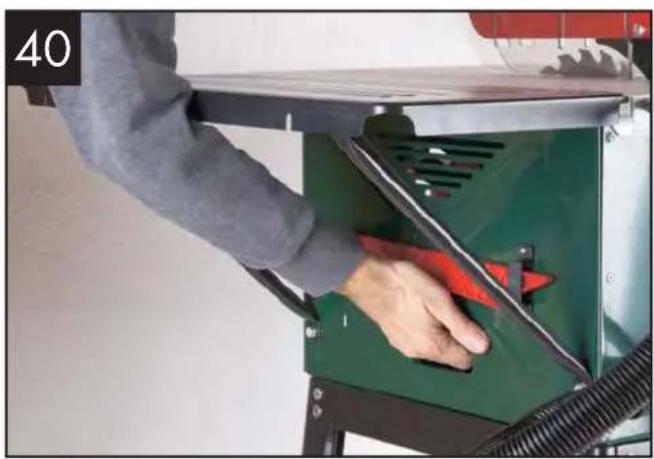
- At least two people should carry the power tool. Do not hold the power tool by the table width extensions. Please use only the transport handles for transporting the machine (Figure 40/41). These are punched into the housing on both sides of the device.
- Protect the power tool against knocks, jolts and strong vibrations, e.g. when it is transported in motor vehicles.
- Secure the power tool against tilting and sliding.
- Never use the protective devices for handling or transport.
Cleaning and Servicing

Remove the mains plug before carrying out any adjustments, maintenance or repair work.

You should have any repair and maintenance work that is not described in these instructions carried out by our Service Centre. Only use original parts.
Perform the following cleaning and maintenance work regularly. This guarantees reliable use for a long time.
Cleaning

The device must not be sprayed with water or placed in water. Otherwise there is a risk of electric shock.
- Keep the safety devices, air vents and motor housing as free of dust and dirt as possible. Wipe the device off with a clean cloth or blow it out with compressed air at a low pressure.
• We recommend that you clean the device immediately after every use. - Clean the device regularly with a damp cloth and some soft soap. Do not use any detergents or solvents; these might attack the plastic parts of the device. Make sure that no water can get into the interior of the device.
- Oil the moving parts once a month in order to extend the tool life. Do not oil the motor.
Storage
- Store the appliance in a dry place well out of reach of children..
Waste disposal and environmental protection
Take the batteries out of the device and recycle the device, batteries, accessories and packaging in an environmentally friendly manner.
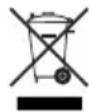
Electrical machines do not belong with domestic waste.
- Dispose of the batteries according to local standards. Hand in the batteries at a used battery collection point where they are recycled in an environmentally friendly manner. For more information, please contact your local waste management provider or our service centre.
- Defective units returned to us will be disposed of for free..
Spare parts/Accessories
Spare parts and accessories can be obtained at www.grizzly-service.eu
If you do not have internet access, please contact the Service Centre via telephone (see "Service-Center" page 57). Please have the order number mentioned below ready.
(14) Parallel stop, complete.... Order number 91103530
(8) Transverse stop, complete .... Order number 91103531
(2) Blade guard, complete .... Order number 91103532
(15) Table length extender .... Order number 91103533
(6) Table insert.... Order number 91103534
(7) Table width extender (right/left).... Order number 91103535
(34) Laser Order number 91103536
(4) Riving knife .... Order number 91103537
(12) Handwheel, complete.... Order number 91103538
(3) Suction hose.... Order number 91103539
(17) Push stick .... Order number 91103540
(11) On/off switch, complete .... Order number 91103541
(24) Stand brackets (both sides).... Order number 91103542
(10) Base, complete .... Order number 91103543
(23) Rubber feet.... Order number 91103544
(r+s) Tool Set .... Order number 91103545
(5) Saw blade 24 Teeth .... Order number 03800400
(5) Saw blade 48 Teeth .... Order number 03800401
Guarantee
Dear Customer,
This equipment is provided with a 3-year guarantee from the date of purchase. In case of defects, you have statutory rights against the seller of the product. These statutory rights are not restricted by our guarantee presented below.
Terms of Guarantee
The term of the guarantee begins on the date of purchase. Please retain the original receipt. This document is required as proof of purchase.
If a material or manufacturing defect occurs within three years of the date of purchase of this product, we will repair or replace – at our choice – the product for you free of charge. This guarantee requires the defective equipment and proof of purchase to be presented within the three-year period with a brief written description of what constitutes the defect and when it occurred.
If the defect is covered by our guarantee, you will receive either the repaired product or a new product. No new guarantee period begins on repair or replacement of the product.
Guarantee Period and Statutory Claims for Defects
The guarantee period is not extended by the guarantee service. This also applies for replaced or repaired parts. Any damages and defects already present at the time of purchase must be reported immediately after unpacking. Repairs arising after expiry of the guarantee period are chargeable.
Guarantee Cover
The equipment has been carefully produced in accordance with strict quality guidelines and conscientiously checked prior to delivery.
The guarantee applies for all material and manufacturing defects. This guarantee does not extend to cover product parts that are subject to normal wear and may therefore be considered as wearing parts (e.g. filters or attachments) or to cover damage to breakable parts (e.g. switches, batteries, or parts made of glass).
This guarantee shall be invalid if the product has been damaged, used incorrectly or not maintained. Precise adherence to all of the instructions specified in the operating manual is required for proper use of the product. Intended uses and actions against which the operating manual advises or warns must be categorically avoided.
The product is designed only for private and not commercial use. The guarantee will be invalidated in case of misuse or improper handling, use of force, or interventions not undertaken by our authorised service branch.
Processing in Case of Guarantee
To ensure efficient handling of your query, please follow the directions below:
- Please have the receipt and identification number (IAN 273460) ready as proof of purchase for all enquiries.
- Please find the item number on the rating plate.
- Should functional errors or other defects occur, please initially contact the service department specified below by telephone or by e-mail. You will then receive further information on the processing of your complaint.
- After consultation with our customer service, a product recorded as defective can be sent postage paid to the service address communicated to you, with the proof of purchase (receipt) and specification of what constitutes the defect and when it occurred. In order to avoid acceptance problems and additional costs, please be sure to use only the address communicated to you. Ensure that the consignment is not sent carriage forward or by bulky goods, express or other special freight. Please send the equipment inc. all accessories supplied at the time of purchase and ensure adequate, safe transport packaging.
Repair Service
For a charge, repairs not covered by the guarantee can be carried out by our service branch, which will be happy to issue a cost estimate for you.
We can handle only equipment that has been sent with adequate packaging and postage.
Attention: Please send your equipment to our service branch in clean condition and with an indication of the defect.
Equipment sent carriage forward or by bulky goods, express or other special freight will not be accepted.
We will dispose of your defective devices free of charge when you send them to us.
Trouble shooting
| Problem | Possible cause | Fault correction |
| 1. Blade dissolves after switching off the engine | To slightly tightened fastening nut Tighten the right | hand thread nut |
| 2. Engine will not start a) Failure | ure mains fuse a) Check mains fuse | |
| b) Defective extension cable b) Replace extension cord | ||
| c) Connections on motor or switch not in order c) | Repair by electrical specialist | |
| d) Motor or switch faulty d) Repair by electrical specialist | ||
| 3. Motor wrong direction of rotation | a) Capacitor faulty a) Repair by electrical specialist | |
| b) Wrong connection b) Exchange polarity of outlet by an qualified electrician | ||
| 4. Motor will not work, the fuse is activ | a) Cross section of the extension cable does not sufficiently | a) see „Electrical connection" |
| b) Overload by a blunt saw blade b) Change saw blade | ||
| 5. Fire marks on the cutting surface | a) blunt saw blade a) Sharpen or change saw blade | |
| b) wrong saw blade | b) Change saw blade | |
Service-Center

Service Great Britain
Tel.: 0871 5000 720
(£ 0.10/Min.)
E-Mail: grizzly@lidl.co.uk
IAN 273460

Service Ireland
Tel.: 1890 930 034
(0,08 EUR/Min., (peak))
(0,06 EUR/Min., (off peak))
E-Mail: grizzly@lidl.ie
IAN 273460
Importer
Please note that the following address is not a service address. Please initially contact the service centre specified above.
Attention! - laser radiation Do not stare into beam!
class 2 laser product laser specification according to EN 60825-1:2007 =650 nm P_0<1 mW

Afzuigadapter monteren 98
Splijtwig monteren 99
Zaagbladbeschermer monteren/ demonteren 99
Attention! - laser radiation Do not stare into beam!
class 2 laser product
laser specification according to EN 60825-1:2007
= 650 ~nm P_0 < 1 mW
Attention! - laser radiation Do not stare into beam!
class 2 laser product
laser specification according to EN 60825-1:2007
= 650 ~nm P_0 < 1 mW
Attention! - laser radiation Do not stare into beam!
class 2 laser product
laser specification according to EN 60825-1:2007
= 650 ~nm P_0 < 1 mW
| GBIE | Translation of the original EC declaration of conformity |
| We hereby confirm that the Table circular saw Design Series PTK 2000 B2 Serial number 201601000001 - 201601024050 conforms with the following applicable relevant version of the EU guidelines : | |
| 2006/42/EC • 2014/30/EU • 2011/65/EU* | |
| In order to guarantee consistency, the following harmonised standards as well as national standards and stipulations have been applied: | |
| EN 61029-1:2009+A11:2010 • EN 61029-2-1:2012 EN 55014-1:2006+A2:2011 • EN 55014-2:1997+A2:2008 EN 61000-3-2:2014 • EN 61000-3-11:2000 EN ISO 12100:2010 • EN 61010-1:2010 EN 60825-1:2007 • EN 61000-6-1:2007 EN 61000-6-3:2007 • EN 847-1:2013 | |
| Registered Office: TÜV Süd, NB 0123 Design Type Certificate No.: M6A 15 11 55256 452 | |
| This declaration of conformity is issued under the sole responsibility of the manufacturer: | |
| CE Grizzly Tools GmbH & Co. KG Stockstädter Straße 20 63762 Großostheim, 30.03.2016 Germany | Volker Lappas Documentation Representative |
* The object of the declaration described above satisfies the provisions of Directive 2011/65/EU of the European Parliament and the Council of 8 June 2011 on limiting the use of certain harmful substances in electrical and electronic appliances.
natural_image
Close-up of hands operating a robotic arm with a red robotic device in the background (no visible text or symbols)

natural_image
Person operating a green industrial machine with a red arrow indicator (no visible text or symbols)
natural_image
Close-up of a hand operating a green industrial machine component with black clamps and mounting brackets (no visible text or symbols)GRIZZLY TOOLS GMBH & CO. KG


- TISCHKREISSÄGE / TABLE SAW / SCIE CIRCULAIRE SUR TABLE PTK 2000 B2
- FR BE
- Inhalt
- Attention! - laser radiation Do not stare into beam!
- Introduction
- Intended purpose
- Caution!
- General description Extent of the delivery
- GBIE
- Mounting Material
- Tools
- Overview
- 1 Saw table ade guard
- Functional description
- Technical data
- Safety instructions
- Symbols and icons
- Symbols on the appliance:
- Symbols in the manual
- Safe operation
- Keep work area clear.
- Consider work area environment.
- Guard against electric shock
- Keep other persons away!
- Store idle tools
- Do not force the tool.
- Use the right tool.
- Dress properly.
- Use protective equipment.
- Connect dust extraction equipment
- Do not abuse the cord.
- Secure work.
- Do not overreach
- Maintain tools with care
- Disconnect tools.
- Remove adjusting keys and wrenches
- Avoid unintentional starting.
- Use outdoor extension leads.
- Stay alert.
- Check damaged parts.
- Warning!
- Have your tool repaired by a qualified person.
- ADDITIONAL SAFETY INSTRUCTIONS
- Safety Precautions
- Maintenance and Servicing
- Safe Working
- SAFETY INSTRUCTIONS FOR HANDLING SAW BLADES
- Assembly and Attachment of Tools and Tool Parts
- Safety Instructions for Handling the Laser
- Safety Instructions for Handling Batteries
- Residual Risks
- Electrical Connection
- Important Instructions
- Faulty Electrical
- Connection Cable
- Alternating Current Motor
- Assembly
- Assembly, Replacement of Parts and Adjustments
- Caution! The mains plug must be removed before all servicing, retooling and assembly work.
- Additional tool required:
- Mounting of the Frame
- Abb.4-10
- Caution! Both stand brackets must be attached to the rear of the machine at attachment points 38!
- Mounting the table width and length extension (Figures 11-14)
- Mounting the Suction Adapter
- (Figure 15)
- Mounting the Riving Knife (Figures 16-19)
- Caution! Remove the mains plug! The setting of the saw blade (5) must be checked whenever a blade has been replaced.
- Mounting / dismounting the Saw Blade Guard
- (Figures 20/21)
- Replacing the Table Insert (Figures 17 and 22)
- Adjusting / mounting the Riving Knife
- (Figures 16-19)
- Attaching/changing the Saw Blade
- (Figure 22)
- Before putting into operation
- Operation
- Switching on and off (Figure 23)
- Adjusting the Cutting Depth
- (Figure 23)
- Important: the hand wheel (12) has to be pulled out to adjust the cutting depth. When the hand wheel is pressed in, this adjusts the cutting angle.
- Angle Adjustment
- Working with the Parallel Stop
- Adjusting the Stop Height
- (Figures 24-26)
- Turning the Stop Rail
- Adjusting the Cutting Width
- (Figures 27-28)
- Adjusting the Stop Length (Figure 29)
- Adjusting the Parallel Stop (Figure 30)
- Transverse stop (Figure 31)
- Adjusting the Scale of the Transverse Stop
- (Figure 32)
- Using the Laser
- (Figures 33-34)
- Adjusting the Laser
- (Figure 34)
- Working Instructions
- Caution with incision cutting.
- Performing Longitudinal Cuts
- (Figure 35)
- Cutting narrow Workpieces (Figure 36)
- Cutting very narrow Workpieces (Figure 37)
- Performing Bevel Cuts
- (Figure 38)
- Performing Transverse Cuts
- (Figures 31, 39)
- Cutting Chipboard
- Transport
- (Fig. 40/41)
- Cleaning and Servicing
- Cleaning
- The device must not be sprayed with water or placed in water. Otherwise there is a risk of electric shock.
- Storage
- Waste disposal and environmental protection
- Spare parts/Accessories
- Spare parts and accessories can be obtained at www.grizzly-service.eu
- Guarantee
- Terms of Guarantee
- Guarantee Period and Statutory Claims for Defects
- Guarantee Cover
- Processing in Case of Guarantee
- Repair Service
- Service-Center
- Service Great Britain
- Service Ireland
- Importer
Brand : PARKSIDE
Model : PTK 2000 B2
Category : Sander