IS 2300 ECO - Motion detector STEINEL - Free user manual and instructions
Find the device manual for free IS 2300 ECO STEINEL in PDF.
| Product type | Infrared motion detector |
| Brand | Steinel |
| Model | IS 2300 ECO |
| Dimensions (H x W x D) | 85 x 60 x 95 mm |
| Power supply | 230 – 240 V, 50 Hz |
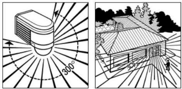
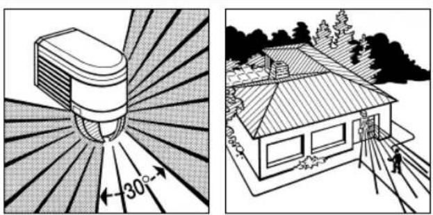
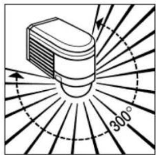
| Detection angle | 300° with angular opening of 180° |
| Maximum range | 12 m (temperature stable) |
| Detection area | Approximately 300 m² |
| Detector adjustability | Precision adjustment ± 80° |
| Time delay | 10 s to 15 min (adjustable) |
| Twilight setting | 2 to 2000 lux (adjustable) |
| Protection rating | IP 54 |
| Maximum power (incandescent/halogen lamps) | 2000 W |
| Maximum power (LED > 8 W) | 64 W |
| Maximum power (fluorescent tubes) | 1000 VA |
| Maximum capacitive load | 176 µF |
| Number of pyroelectric detectors | 3 |
| Recommended mounting height | Approximately 2 m |
| Operating temperature | Not specified, estimated -20°C to +50°C |
| Wiring type | Bipolar (L, N, L') + optional earth |
| Manufacturer warranty | 5 years |
| Maintenance and cleaning | Clean the lens with a damp cloth, without detergent |
| Safety instructions | Cut power before intervention; installation according to NF C-15100 |
Frequently Asked Questions - IS 2300 ECO STEINEL
User questions about IS 2300 ECO STEINEL
0 question about this device. Answer the ones you know or ask your own.
Ask a new question about this device
Download the instructions for your Motion detector in PDF format for free! Find your manual IS 2300 ECO - STEINEL and take your electronic device back in hand. On this page are published all the documents necessary for the use of your device. IS 2300 ECO by STEINEL.
USER MANUAL IS 2300 ECO STEINEL
natural_image
World map silhouette in grayscale, showing continents and oceans without any text or labelsContact
www.steinel.de/contact

GB ⚠ Safety precautions
■ Disconnect the power supply before attempting any work on the motion detector.
During installation, the electric power cable being connected must not be live. Therefore, switch off the power first and use a voltage
tester to make sure the wiring is off circuit.
Installing the sensor involves work on the mains power supply. This work must therefore be carried out professionally in accordance with applicable wiring regula-
tions and electrical operating conditions. (e.g.: DE - VDE
0100, AT - ÖVE / ÖNORM E8001-1, CH - SEV 1000). The mains power connection lead must not be more than 10 mm in diameter.
Wandbefestigung
natural_image
Line drawing of a bird's wing with scissors and striped pattern (no text or symbols)natural_image
Diagram of a mechanical or fluidic component with directional arrows indicating flow or movement (no text or symbols present)natural_image
Diagram of a device emitting radiation with 300° angle marked, radiating outward (no text or symbols)
natural_image
Black-and-white line drawing of a house with a tiled roof, surrounded by trees and a person walking (no text or symbols)2

natural_image
Line drawing of a house with a tiled roof and surrounding trees (no text or symbols)3
natural_image
Diagram of a spray gun emitting radiation, showing radial blades and angle measurement (no text or symbols)
natural_image
Line drawing of a two-story house with a tiled roof and surrounding trees (no text or symbols)natural_image
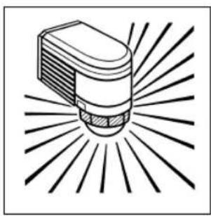
Illustration of a light bulb with radiating lines, no text or symbols present
natural_image
Line drawing of a house with a tiled roof and sun rays, surrounded by trees (no text or symbols)Anschlussbeispiele
10 11
Anschlussbeispiele


GB Installation instructions
STEINEL infrared sensors provide the basis for modem, effi cient security light solutions. When movement is sensed in their detection zone, they switch light 'ON' automatically, providing convenience, safety and security while making effi cient use of energy.
With a total of three integrated pyro-sensors, the IS 2300 ECO
motion detector senses the heat or infrared radiation - invisible to the human eye - that is emitted from objects (people, animals etc.) moving in its detection zone. The heat detected is converted into an electronic signal that switches one or several loads, e.g. lights, 'ON' or, when the moving object leaves the detection zone, 'OFF' again after a pro-
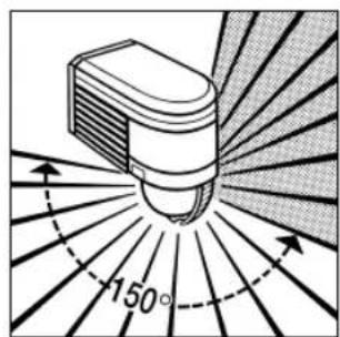
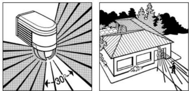
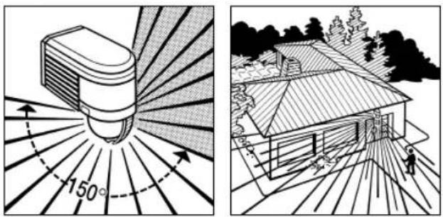
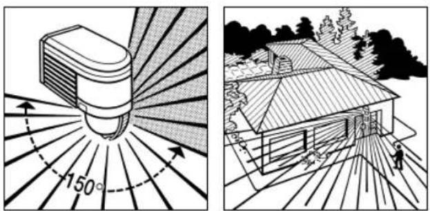
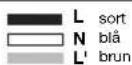
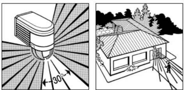
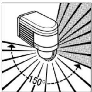
grammed period. As heat radiation is not detected through obstacles, such as walls or panes of glass, it does not trigger the sensor. The IS 2300 ECO has an angle of coverage of 300^ with an aperture angle of 180^ . This means it can cover an area of approx. 300m^2 .
IS 2300 ECO
Reach
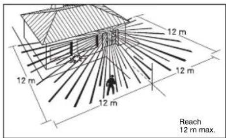
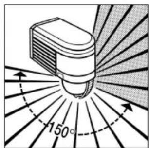
Important: The most reliable way of detecting movement is to install the unit with the sensor aimed across the direction in which a person would walk and by ensuring that no obstacles (such as trees, walls etc.) obstruct the line of sensor vision.
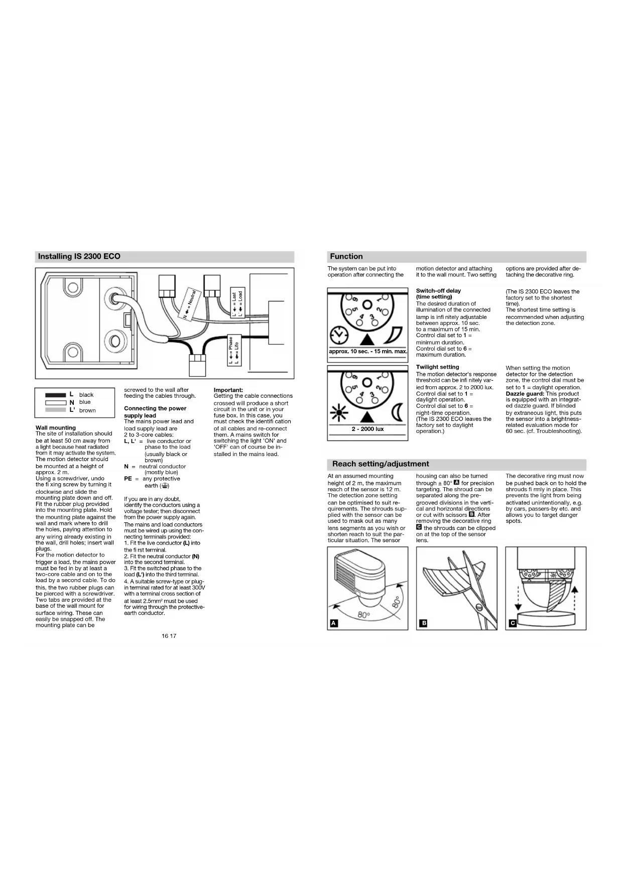
Installing IS 2300 ECO

Wall mounting
The site of installation should be at least 50 cm away from a light because heat radiated from it may activate the system. The motion detector should be mounted at a height of approx. 2 m.
Using a screwdriver, undo the fixing screw by turning it clockwise and slide the mounting plate down and off. Fit the rubber plug provided into the mounting plate. Hold the mounting plate against the wall and mark where to drill the holes, paying attention to any wiring already existing in the wall, drill holes; insert wall plugs.
For the motion detector to trigger a load, the mains power must be fed in by at least a two-core cable and on to the load by a second cable. To do this, the two rubber plugs can be pierced with a screwdriver. Two tabs are provided at the base of the wall mount for surface wiring. These can easily be snapped off. The mounting plate can be
screwed to the wall after feeding the cables through.
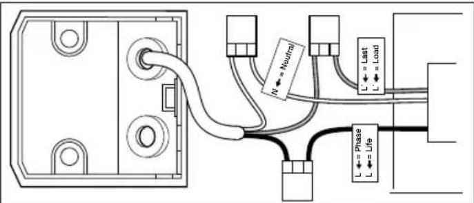
Connecting the power supply lead
The mains power lead and load supply lead are 2 to 3-core cables:
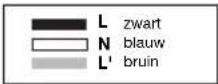
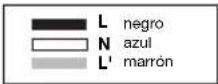
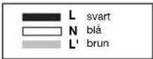
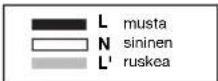
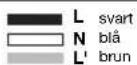
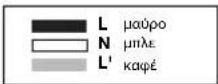
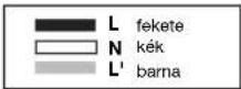
L, L' = live conductor or phase to the load (usually black or brown)
N = neutral conductor (mostly blue)
PE = any protective earth (±)
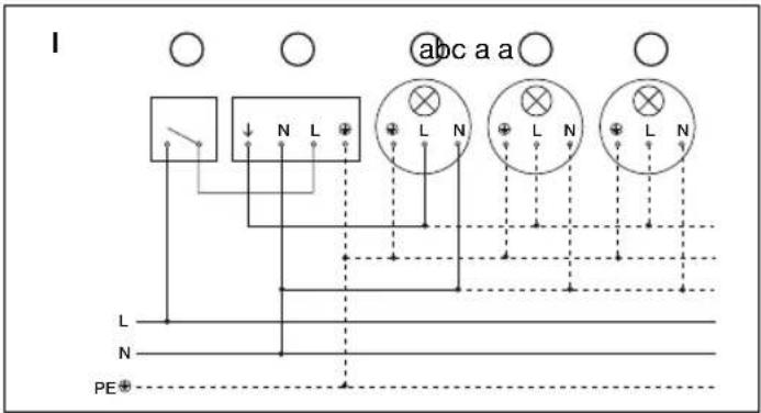
If you are in any doubt, identify the conductors using a voltage tester; then disconnect from the power supply again. The mains and load conductors must be wired up using the connecting terminals provided: 1. Fit the live conductor (L) into the first terminal. 2. Fit the neutral conductor (N) into the second terminal. 3. Fit the switched phase to the load (L') into the third terminal. 4. A suitable screw-type or plug-in terminal rated for at least 300V with a terminal cross section of at least 2.5mm^2 must be used for wiring through the protective-earth conductor.
Important:
Getting the cable connections crossed will produce a short circuit in the unit or in your fuse box. In this case, you must check the identification of all cables and re-connect them. A mains switch for switching the light 'ON' and 'OFF' can of course be installed in the mains lead.
Function
The system can be put into operation after connecting the
motion detector and attaching it to the wall mount. Two setting
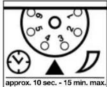
Switch-off delay (time setting)
The desired duration of illumination of the connected lamp is infinitely adjustable between approx. 10 sec. to a maximum of 15 min. Control dial set to 1 = minimum duration. Control dial set to 6 = maximum duration.
options are provided after detaching the decorative ring.
(The IS 2300 ECO leaves the factory set to the shortest time). The shortest time setting is recommended when adjusting the detection zone.
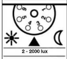
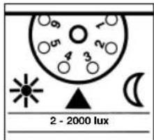
Twilight setting
The motion detector's response threshold can be infinitely varied from approx. 2 to 2000 lux. Control dial set to 1 = daylight operation. Control dial set to 6 = night-time operation. (The IS 2300 ECO leaves the factory set to daylight operation.)
When setting the motion detector for the detection zone, the control dial must be set to 1 = daylight operation. Dazzle guard: This product is equipped with an integrated dazzle guard. If blinded by extraneous light, this puts the sensor into a brightness-related evaluation mode for 60 sec. (cf. Troubleshooting).
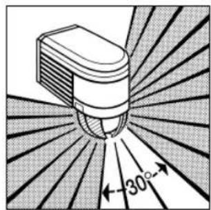
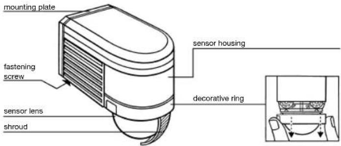
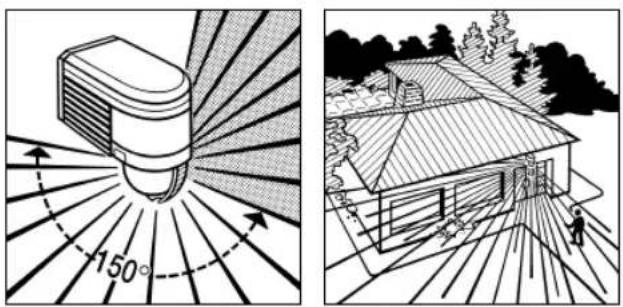
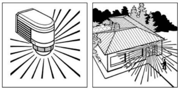
Reach setting/adjustment
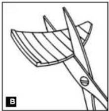
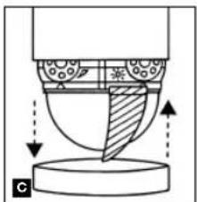
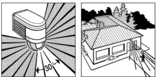
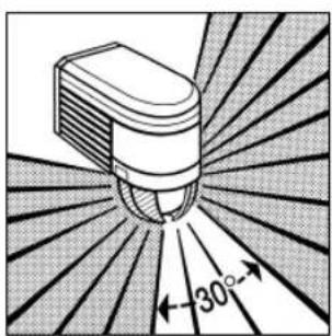
At an assumed mounting height of 2 m, the maximum reach of the sensor is 12 m. The detection zone setting can be optimised to suit requirements. The shrouds supplied with the sensor can be used to mask out as many lens segments as you wish or shorten reach to suit the particular situation. The sensor
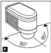
housing can also be turned through ± 80^ for precision targeting. The shroud can be separated along the pre-grooved divisions in the vertical and horizontal directions or cut with scissors. After removing the decorative ring the shrouds can be clipped on at the top of the sensor lens.
natural_image
Line drawing of a mechanical part with blades and a cutting tool (no text or symbols)The decorative ring must now be pushed back on to hold the shrouds fl rmly in place. This prevents the light from being activated unintentionally, e.g. by cars, passers-by etc. and allows you to target danger spots.
natural_image
Diagram of a mechanical or fluidic component with directional arrows indicating flow or movement (no text or symbols present)Reach setting / examples
1
natural_image
Two-panel illustration: left shows a sunlit cylindrical object with 300° rotation, right shows a house with a person walking nearby (no text or symbols)2
natural_image
Two-panel illustration: left shows a sunlit bulb emitting rays, right shows a house with a person walking (no text or symbols)3

natural_image
Two-panel illustration: left shows a sunburst device with 30° angle, right shows a house with trees and pathways (no text or symbols)18 19
Reach setting / examples
4
natural_image
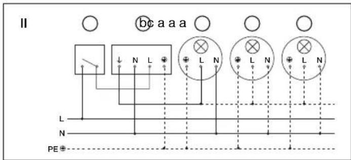
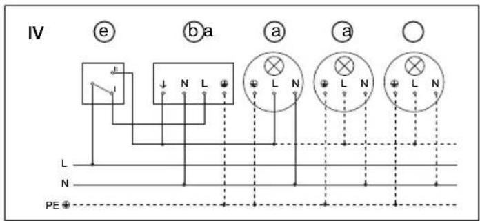
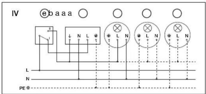
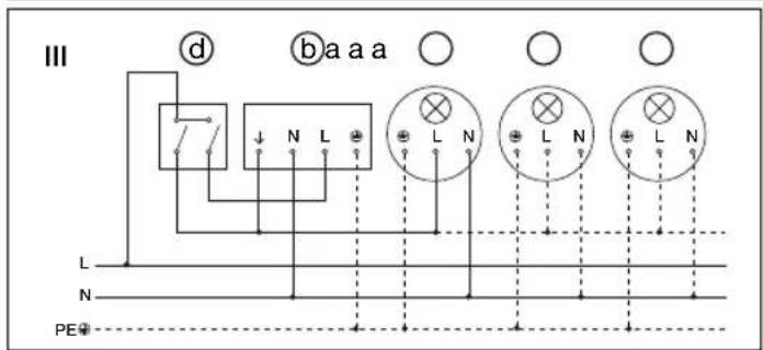
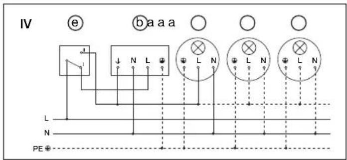
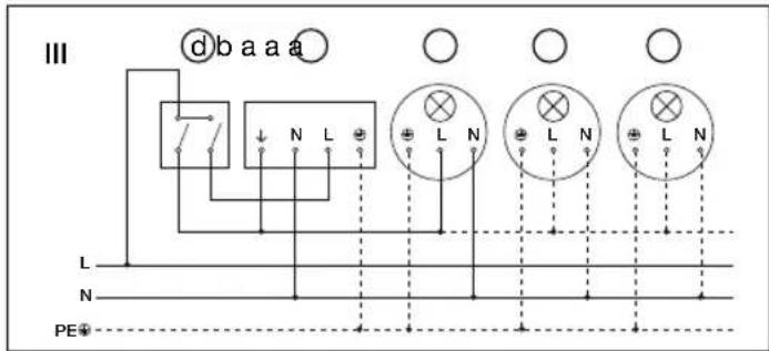
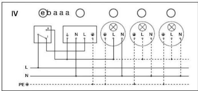
Two black-and-white illustrations: one showing a light bulb with radiating lines, the other showing a house with sun rays and a person walking nearby (no text or symbols)Connection examples
I. Light without neutral conductor
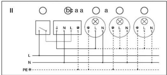
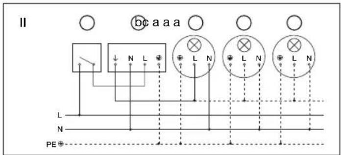
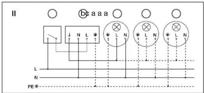
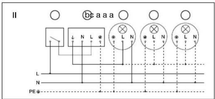
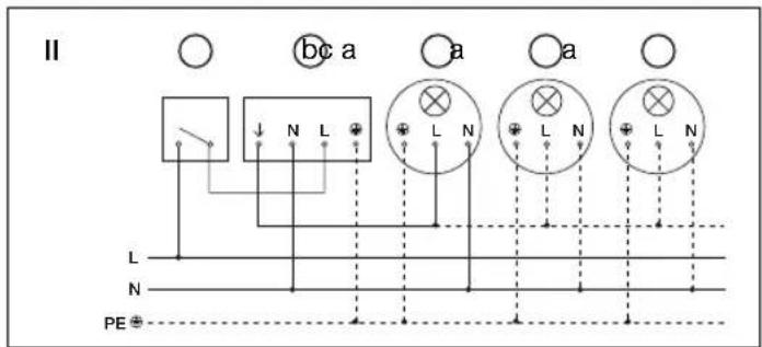
II. Light with neutral conductor
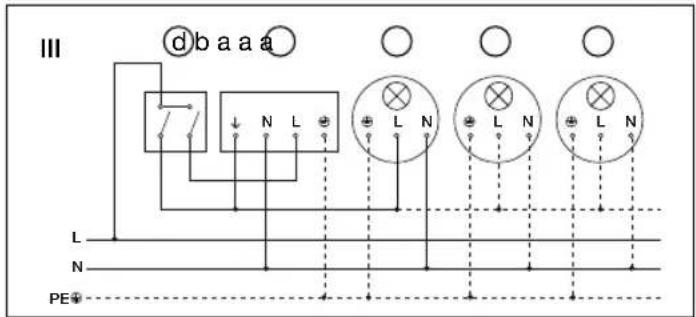
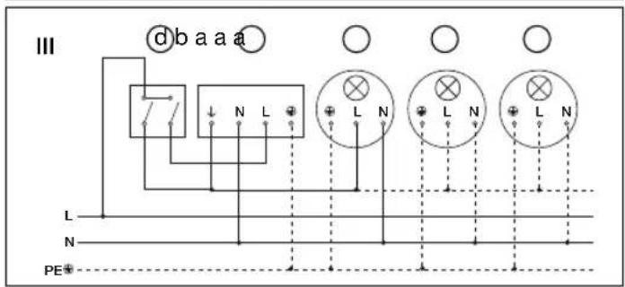
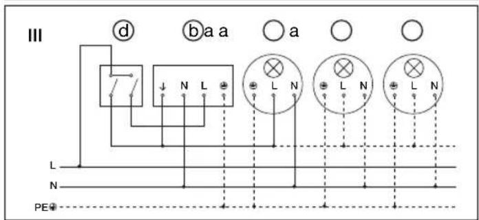
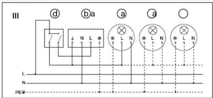
III. Connection using indoor two-circuit single interruption switch for manual and automatic operation
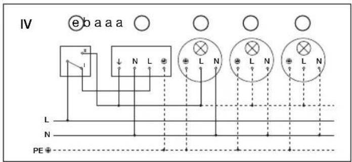
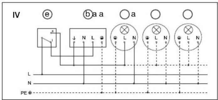
IV. Connection using an indoor two-way switch for manual override and automatic operation
Setting I: Automatic operation
Setting II: Manual operation, light permanently 'ON'
Note: The system cannot be switched 'OFF', it is only possible to select operation at setting I or II.
Connection examples
flowchart
graph TD
    A["Component L"] --> B["Switch"]
    C["N"] --> D["Switch"]
    E["PE"] --> F["Switch"]
    G["L"] --> H["Switch"]
    I["L"] --> J["Switch"]
    K["L"] --> L["Switch"]
    M["L"] --> N["Switch"]
    O["L"] --> P["Switch"]
    Q["L"] --> R["Switch"]
    S["L"] --> T["Switch"]
    U["L"] --> V["Switch"]
    W["L"] --> X["Switch"]
    Y["L"] --> Z["Switch"]
    AA["L"] --> AB["Switch"]
    AC["L"] --> AD["Switch"]
    AE["L"] --> AF["Switch"]
    AG["L"] --> AH["Switch"]
    AI["L"] --> AJ["Switch"]
    AK["L"] --> AL["Switch"]
    AM["L"] --> AN["Switch"]
    AO["L"] --> AP["Switch"]
    AQ["L"] --> AR["Switch"]
    AS["L"] --> AT["Switch"]
    AU["L"] --> AV["Switch"]
    AW["L"] --> AX["Switch"]
    AY["L"] --> Z
    Z --> AA
    AA --> AB
    AB --> AC
    AC --> AD
    AD --> AE
    AE --> AF
    AF --> AG
    AG --> AH
    AH --> AI
    AI --> AJ
    AJ --> AK
    AK --> AL
    AL --> AM
    AM --> AN
    AN --> AO
    AO --> AP
    AP --> AQ
    AQ --> AR
    AR --> AS
    AS --> AT
    AT --> AU
    AU --> AV
    AV --> AW
    AW --> AX
    AX --> AO
    AO --> AP
    AP --> AQ
    AQ --> AR
    AR --> AS
    AS --> AT
    AT --> AU
    AU --> AV
    AV --> AW
    AW --> AX
    AX --> AO
    AO --> AP
    AP --> AQ
    AQ --> AH
    AH --> AI
    AI --> AJ
    AJ --> AK
    AK --> AL
    AL --> AM
    AM --> AN
    AN --> AO
    AO --> AP
    AP --> AQ
    AQ --> AH
    AH --> AI
    AI --> AJ

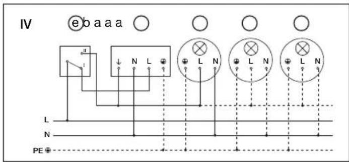
a) Loads, lighting of 2000 W max. (see Technical specifications)
b) IS 2300 ECO connection terminals
c) Indoor switch
d) Indoor two-circuit single interruption switch, manual operation, automatic operation
e) Indoor two-way switch, automatic operation, manual override
Operation / Maintenance
The motion detector is suitable for switching a light 'ON' or triggering an alarm. The motion detector is not suitable for burglar-alam systems as it does not provide the level of sabotage protection that is prescribed for this purpose.
Weather conditions may affect
the way the motion detector
works. Strong gusts of wind.
snow, rain or hail may cause the
light to come 'ON' when it is
not wanted because the sensor
is unable to distinguish sudden
changes of temperature from
sources of heat. The detector
lens may be cleaned with a
damp cloth if it gets dirty (do
not use cleaning agents).
Technical specifications
| Dimensions (H × W × D): 85 × 60 × 95 mm | |
| Output: Incandescent / halogen lamp load 2000 W | |
| Fluorescent-lamp electronic ballasts 1000 W | |
| Fluorescent lamps, uncorrected 1000 VA | |
| Fluorescent lamps, series-corrected 1000 VA | |
| Fluorescent lamps, parallel-corrected 1000 VA | |
| Low-voltage halogen lamps 2000 VA | |
| LED < 2 W 16 W | |
| 2 W < LED < 8 W 64 W | |
| LED > 8 W 64 W | |
| Capacitive load 176 μF | |
| Power supply: 230 – 240 V, 50 Hz | |
| Angle of coverage: 300° with 180° angle of aperture | |
| Sensor swivelling range: precision targeting ± 80° | |
| Reach: max. 12 m max.; temperature-stabilised | |
| Time setting: 10 sec. – 15 min. | |
| Twilight setting: 2 – 2000 lux | |
| IP rating: IP 54 |
Troubleshooting
Malfunction Cause Remedy
| Without power | ■Fuse blown, not switched 'ON'■Short circuit | ■Replace fuse, switch 'ON' mains switch, check lead with voltage tester■Check connections |
| Does not switch 'ON' | ■Twilight setting in night-time mode during daytime operation■Bulb faulty■Mains switch 'OFF'■Fuse faulty■Detection zone not properly targeted | ■Adjust setting■Change bulb■Switch 'ON'■Fit new fuse, check connection if necessary■Re-adjust |
| Does not switch 'OFF' | ■Continued movement in detection zone■Light is in detection zone and keeps switching 'ON'■Set to continuous operation by indoor two-circuit single interruption switch■Position Wi-Fi device very close to the sensor | ■Check detection zone and re-adjust if necessary or fi t shrouds■Adjust detection zone or fi t shrouds■Set two-circuit single interruption switch to automatic■Increase distance between Wi-Fi device and sensor |
| Keeps switching 'ON'/'OFF' | ■Lamp being operated in the detection zone■Animals moving in detection zone | ■Adjust detection zone or fi t shrouds, increase distance■Adjust detection zone or fi t shrouds |
| Switches 'ON' when it should not | ■Wind is moving trees and bushes in the detection zone■Cars in the street are being detected■Sudden temperature changes due to weather (wind, rain, snow) or air expelled from fans, open windows■Dazzle guard active | ■Adjust detection zone or fi t shrouds■Adjust detection zone or fi t shrouds■Change zone, move site of installation■Switch 'OFF' manually at pushbutton/switch■No movement detected within the selected stay-'ON' time + 60 sec. (dazzle guard)■Increase distance between Wi-Fi device and sensor |
Disposal
Electrical and electronic equipment, accessories and packaging must be recycled in an environmentally compatible manner.

Do not dispose of electrical and electronic equipment as domestic waste.
EU countries only: Under the current European Directive on Waste Electrical and Electronic Equipment and its implementation in national law, electrical and electronic equipment no longer suitable for use must be collected separately and recycled in an environmentally compatible manner.
Manufacturer's warranty
As purchaser, you are entitled to your statutory rights against the vendor. If these rights exist in your country, they are neither curtailed nor restricted by our Warranty Declaration. We guarantee that your STEINEL Professional sensor product will remain in perfect condition and proper working order for a period of 5 years. We guarantee that this product is free from material-, manufacturing- and design flaws. In addition, we guarantee that all electronic components and cables function in the proper manner and that all materials used and their surfaces are without defects.
Making Claims If you wish to make a claim, please send your product complete and carriage paid with the original receipt of purchase, which must show the date of purchase and product designation, either to your retailer or contact us at STEINEL (UK) Limited, 25 Manasty Road, Axis Park, Orton Southgate, Peterborough, PE2 6UP, for a returns number. For this reason, we recommend that you keep your receipt of purchase in a safe place until the warranty period expires. STEINEL shall assume no liability for the costs or risks involved in returning a product.
For information on making claims under the terms of the warranty, please go to www.steinel-professional.de/garantie
If you have a warranty claim or would like to ask any question regarding your product, you are welcome to call us at any time on our Service Hotline 01733 366700.

natural_image
Line drawing of a mechanical part with blades and a circular end, labeled 'B' (no text or symbols on the diagram itself)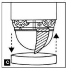
natural_image
Diagram of a mechanical or fluidic component with directional arrows and shaded regions, no readable text or symbols present.26 27
natural_image
Two technical diagrams showing a 300-degree angle of rotation and a 200-degree view of a house with a person walking nearby (no text or symbols)2

natural_image
Two-panel illustration: left shows a sunburst light source with 150° rotation, right shows a house with a person walking (no text or symbols)3
natural_image
Two-panel illustration: left shows a sunburst-shaped device with 30° angle, right shows a house with trees and ground (no text or symbols)natural_image
Illustration of a stylized lamp with radiating lines, no text or symbols present
natural_image
Line drawing of a house with a person walking on a path, surrounded by trees and foliage (no text or symbols)28 29


Wandbevestiging
natural_image
Line drawing of a bird-shaped object with striped wings and scissors, labeled 'B' (no text or symbols on the diagram itself)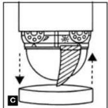
natural_image
Diagram of a mechanical or fluidic component with directional arrows indicating flow or movement (no text or symbols)natural_image
Two technical diagrams showing a 300-degree angle measurement of an object and a 300-degree plan view of a house with trees and a person walking (no text or symbols present)2

natural_image
Two-panel illustration: left shows a sunlit bulb emitting light rays, right shows a house with trees and a person walking (no text or symbols)3

natural_image
Two-panel illustration: left shows a sunburst device with 30° angle, right shows a house with roof and person walking (no text or symbols)36 37
natural_image
Two-panel illustration: left shows a light bulb emitting radiating lines, right shows a house with a person walking nearby (no text or symbols)Aansluitvoorbeelden
Aansluitvoorbeelden

natural_image
Line drawing of a mechanical part with blades and a circular end, labeled 'B' (no text or symbols on the diagram itself)
natural_image
Diagram of a mechanical or fluidic component with directional arrows indicating flow or movement (no text or symbols present)44 45
natural_image
Diagram of a device emitting radiation pattern with 300° angle标注 (no text or symbols beyond the angle marker)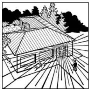
natural_image
Black-and-white line drawing of a house with a tiled roof and surrounding trees (no text or symbols)2


natural_image
Line drawing of a house with a tiled roof and surrounding trees (no text or symbols)3

natural_image
Diagram of a spray gun emitting radiation, showing radial blades and a 30-degree angle indicator (no text or symbols beyond directional arrows)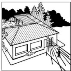
natural_image
Line drawing of a two-story house with a tiled roof, surrounded by trees and a person walking on a path (no text or symbols)natural_image
Illustration of a stylized lamp with radiating lines, no text or symbols present
natural_image
Line drawing of a house with a person walking on a path, surrounded by trees and foliage (no text or symbols)46 47


Montaje en la pared
natural_image
Line drawing of a pair of scissors cutting through a wing (no text or symbols)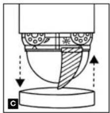
natural_image
Diagram of a mechanical or fluidic component with directional arrows indicating flow or movement (no text or symbols)natural_image
Two-panel illustration: left shows a cylindrical object with 300° rotation and radial lines, right shows a house with a person walking on a path (no text or symbols)2
natural_image
Two-panel illustration: left shows a sunlit bulb emitting rays, right shows a house with trees and a person walking (no text or symbols)3
natural_image
Two technical illustrations: one showing a sunburst device with 30° angle, the other showing a house with trees and ground (no text or symbols)54 55
natural_image
Two black-and-white illustrations: one showing a light bulb emitting radiating lines, the other showing a house with a person walking nearby (no text or symbols)
natural_image
Line drawing of a mechanical part with blades and a circular end, labeled 'B' (no text or symbols on the diagram itself)
natural_image
Diagram of a mechanical or fluidic component with directional arrows and shaded regions, no readable text or symbols present.62 63
natural_image
Diagram of a device emitting radiation pattern with 300° angle标注 (no text or symbols beyond the angle marker)
natural_image
Black-and-white line drawing of a house with a tiled roof and surrounding trees (no text or symbols)2


natural_image
Line drawing of a house with a tiled roof and surrounding trees (no text or symbols)3

natural_image
Diagram of a spray gun emitting radiation, showing radial blades and a 30-degree angle indicator (no text or symbols beyond directional arrows)
natural_image
Line drawing of a two-story house with a tiled roof and surrounding trees (no text or symbols)natural_image
Illustration of a light bulb with radiating lines, no text or symbols present
natural_image
Line drawing of a modern house with a chimney and surrounding trees (no text or symbols)Exemplos de conexão
64 65
Exemplos de conexão


Väggmontage
natural_image
Line drawing of a pair of scissors cutting through a blade (no text or symbols)
natural_image
Diagram of a mechanical or fluidic component with directional arrows indicating flow or movement (no text or symbols)natural_image
Two-panel illustration: left shows a cylindrical device with 300° rotation and radial lines, right shows a house with a person walking on a path (no text or symbols)2
natural_image
Two-panel illustration: left shows a sunburst light source with 150° rotation, right shows a house with trees and a person walking (no text or symbols)3
natural_image
Two-panel illustration: left shows a sunburst-shaped device with 30° angle标注, right shows a house with roof and utility pole (no text or symbols)72 73
natural_image
Two black-and-white illustrations: one showing a light bulb with radiating lines, the other showing a house with sun rays and a person walking nearby (no text or symbols)Kopplingsschema
Kopplingsschema
Vægmontering
natural_image
Line drawing of a pair of scissors cutting through a blade (no text or symbols)
natural_image
Cross-sectional diagram of a mechanical component with shaded areas and arrows indicating motion (no text or symbols)natural_image
Diagram of a device emitting radiation with 300° angle marked, radiating outward (no text or symbols)
natural_image
Black-and-white line drawing of a house with a tiled roof, surrounded by trees and a person walking on the ground (no text or symbols)2

natural_image
Line drawing of a house with a tiled roof and surrounding trees (no text or symbols)3

natural_image
Diagram of a spray gun emitting radiation, showing radial blades and angle标注 (no text or symbols beyond measurement)
natural_image
Line drawing of a two-story house with a tiled roof, surrounded by trees and a person walking on a path (no text or symbols)natural_image
Illustration of a stylized lamp with radiating lines, no text or symbols present
natural_image
Line drawing of a house with a person walking on a path, surrounded by trees and foliage (no text or symbols)82 83
a) Forbrugere, lys med maks. 2000 W (se Tekniske data)
b) Tilslutningsklemmer for IS 2300 ECO
c) Indendørs afbryder
d) Enkelt indendørs tokredsaforyder, manuel drift, automatisk drift
e) Indendors tovejs-afbryder, automatisk drift, manuel omgåelse
Asennus seinään
natural_image
Line drawing of a pair of scissors cutting a wing, no text or symbols present
natural_image
Diagram of a mechanical or fluidic component with directional arrows indicating flow or movement (no text or symbols)natural_image
Two technical diagrams showing a 300-degree angle measurement of an object and a 200-degree view of a house with trees and a person walking (no text or symbols present)2

natural_image
Two-panel illustration: left shows a sunburst light source with 150° rotation, right shows a house with trees and a person walking (no text or symbols)3
natural_image
Two-panel illustration: left shows a sunburst device with 30° angle, right shows a house with trees and pathways (no text or symbols)90 91
natural_image
Two black-and-white illustrations: one showing a light bulb with radiating lines, the other showing a house with a person walking and a tree in the background (no text or symbols)Liitäntäesimerkkejä
Liitäntäesimerkkejä

flowchart
graph TD
    A["Component L"] --> B["Switch"]
    C["N"] --> D["Switch"]
    E["PE"] --> F["Switch"]
    G["L"] --> H["Switch"]
    I["L"] --> J["Switch"]
    K["L"] --> L["Switch"]
    M["L"] --> N["Switch"]
    O["L"] --> P["Switch"]
    Q["L"] --> R["Switch"]
    S["L"] --> T["Switch"]
    U["L"] --> V["Switch"]
    W["L"] --> X["Switch"]
    Y["L"] --> Z["Switch"]
    AA["L"] --> AB["Switch"]
    AC["L"] --> AD["Switch"]
    AE["L"] --> AF["Switch"]
    AG["L"] --> AH["Switch"]
    AI["L"] --> AJ["Switch"]
    AK["L"] --> AL["Switch"]
    AM["L"] --> AN["Switch"]
    AO["L"] --> AP["Switch"]
    AQ["L"] --> AR["Switch"]
    AS["L"] --> AT["Switch"]
    AU["L"] --> AV["Switch"]
    AW["L"] --> AX["Switch"]
    AY["L"] --> Z
    Z --> AA
    AA --> AB
    AB --> AC
    AC --> AD
    AD --> AE
    AE --> AF
    AF --> AG
    AG --> AH
    AH --> AI
    AI --> AJ
    AJ --> AK
    AK --> AL
    AL --> AM
    AM --> AN
    AN --> AO
    AO --> AP
    AP --> AQ
    AQ --> AR
    AR --> AS
    AS --> AT
    AT --> AU
    AU --> AV
    AV --> AW
    AW --> AX
    AX --> AO
    AO --> AP
    AP --> AQ
    AQ --> AR
    AR --> AS
    AS --> AT
    AT --> AU
    AU --> AV
    AV --> AW
    AW --> AX
    AX --> AO
    AO --> AP
    AP --> AQ
    AQ --> AH
    AH --> AI
    AI --> AJ
    AJ --> AK
    AK --> AL
    AL --> AM
    AM --> AN
    AN --> AO
    AO --> AP
    AP --> AQ
    AQ --> AH
    AH --> AI
    AI --> AJ
Feste på vegg
Rekkeviddeinnstilling/justering
natural_image
Line drawing of a mechanical part with blades and a circular end (no text or symbols)98 99
natural_image
Diagram of a mechanical or fluidic component with directional arrows and shaded regions, no readable text or symbols present.Rekkeviddeinnstilling/eksempler
1
natural_image
Diagram of a device emitting radiation pattern with 300° angle标注 (no text or symbols beyond the angle marker)
natural_image
Black-and-white line drawing of a house with a tiled roof and surrounding trees (no text or symbols)2


natural_image
Line drawing of a house with a tiled roof and surrounding trees (no text or symbols)3

natural_image
Diagram of a spray gun emitting radiation, showing radial blades and a 30-degree angle indicator (no text or symbols beyond the angle marker)
natural_image
Line drawing of a two-story house with a tiled roof and surrounding trees (no text or symbols)Rekkeviddeinnstilling/eksempler
4
natural_image
Illustration of a stylized lamp with radiating lines, no text or symbols present
natural_image
Line drawing of a house with a person walking on a path, surrounded by trees and foliage (no text or symbols)100 101
Στερέωση στον τοίχο
natural_image
Line drawing of a pair of scissors cutting a sheet metal, no text or symbols present
natural_image
Diagram of a mechanical or fluidic component with directional arrows indicating flow or movement (no text or symbols present)natural_image
Two technical diagrams showing a device emitting radiation and a house with a person walking nearby (no text or symbols)2

natural_image
Two-panel illustration: left shows a sunburst light source with 150° rotation, right shows a house with trees and a person walking (no text or symbols)3

natural_image
Two-panel illustration: left shows a sunburst device with 30° angle, right shows a house with roof and person walking (no text or symbols)108 109
natural_image
Two-panel illustration: left shows a light bulb emitting radiating lines, right shows a house with a person walking nearby (no text or symbols)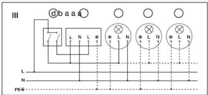


L siyah
N mavi
L' kahverengi
Duvar montaji
natural_image
Line drawing of a mechanical part with scissors and blades, no text or symbols present
natural_image
Diagram of a mechanical or fluidic component with directional arrows indicating flow or movement (no text or symbols present)116 117
natural_image
Two-panel illustration: left shows a sunlit cylindrical object with 300° rotation, right shows a house with a person walking and a tree in the background (no text or symbols)2

natural_image
Two-panel illustration: left shows a sunburst light source with 150° rotation, right shows a house with a person walking (no text or symbols)3

natural_image
Two-panel illustration: left shows a sunburst-shaped device with 30° angle, right shows a house with trees and ground (no text or symbols)natural_image
Illustration of a stylized lamp with radiating lines, no text or symbols present
natural_image
Line drawing of a house with a person walking on a path, surrounded by trees and foliage (no text or symbols)Bağlantı Örnekleri
I. Nõtr iletken bulunmayan lambalar
II. Nötr iletkeni bulunan lambalar
118 119
Bağlantı Örnekleri

Felszerelés a falra
natural_image
Line drawing of a pair of scissors cutting through a blade (no text or symbols)
natural_image
Diagram of a mechanical or fluidic component with directional arrows indicating flow or movement (no text or symbols)natural_image
Diagram of a cylindrical device with radial lines and a 300° angle标注 (no text or symbols beyond the angle marker)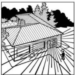
natural_image
Black-and-white line drawing of a house with a tiled roof and surrounding trees (no text or symbols)2
natural_image
Diagram of a light bulb emitting rays, showing 150-degree angle and directional arrows (no text or symbols)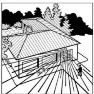
natural_image
Line drawing of a house with a tiled roof and surrounding trees (no text or symbols)3
natural_image
Diagram of a mechanical component with angular measurement (30°) and radial lines, no readable text or symbols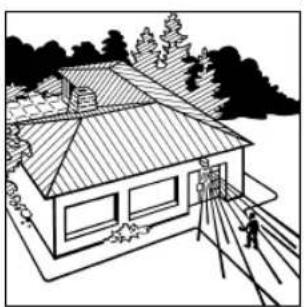
natural_image
Line drawing of a house with tiled roof and surrounding trees (no text or symbols)126 127
natural_image
Illustration of a light bulb with radiating lines, no text or symbols present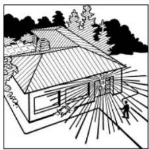
natural_image
Line drawing of a modern house with a person walking nearby, surrounded by trees and foliage (no text or symbols)Példák a bekötésre
Példák a bekötésre


128 129