BDL230S - Laser pointer BLACK & DECKER - Free user manual and instructions
Find the device manual for free BDL230S BLACK & DECKER in PDF.
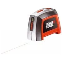
| Product Type | Multifunction laser pointer (laser level, stud finder, metal and live wire detector) |
| Brand | Black & Decker |
| Model | BDL230S |
| Power Supply | 1 9V battery (type 6LR61) |
| Weight | 0.45 kg |
| Laser Wavelength | 630 - 675 nm |
| Laser Class | Class 2 (EN 60825-1), power < 2.2 mW |
| Laser Level Accuracy (at 3 m) | ± 3 mm |
| Operating Temperature | 0 °C to 40 °C |
| Main Functions | Self-leveling, laser line projection, stud detection (wood and metal), metal detection, live wire detection (230 V~) |
| Stud Detection | Up to 19 mm drywall thickness |
| Metal Detection | Up to 25 mm drywall thickness |
| Live Wire Detection | Up to 38 mm drywall thickness |
| Display | LCD screen with scanner bars and low battery indicator |
| Wall Mount | Wall anchor and keyhole mount included |
| Maintenance and Cleaning | Clean with a soft, dry cloth. Do not use solvents or abrasive products. |
| Safety | Do not look directly into the laser beam. Keep out of reach of children under 16. Use in accordance with laser class 2. |
| Spare Parts and Repairability | Repairs must be carried out by a Black & Decker approved technician. Batteries and accessories available. |
| Warranty | 24 months, subject to the conditions described in the manual. |
Frequently Asked Questions - BDL230S BLACK & DECKER
User questions about BDL230S BLACK & DECKER
0 question about this device. Answer the ones you know or ask your own.
Ask a new question about this device
Download the instructions for your Laser pointer in PDF format for free! Find your manual BDL230S - BLACK & DECKER and take your electronic device back in hand. On this page are published all the documents necessary for the use of your device. BDL230S by BLACK & DECKER.
USER MANUAL BDL230S BLACK & DECKER
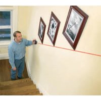
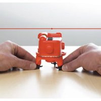
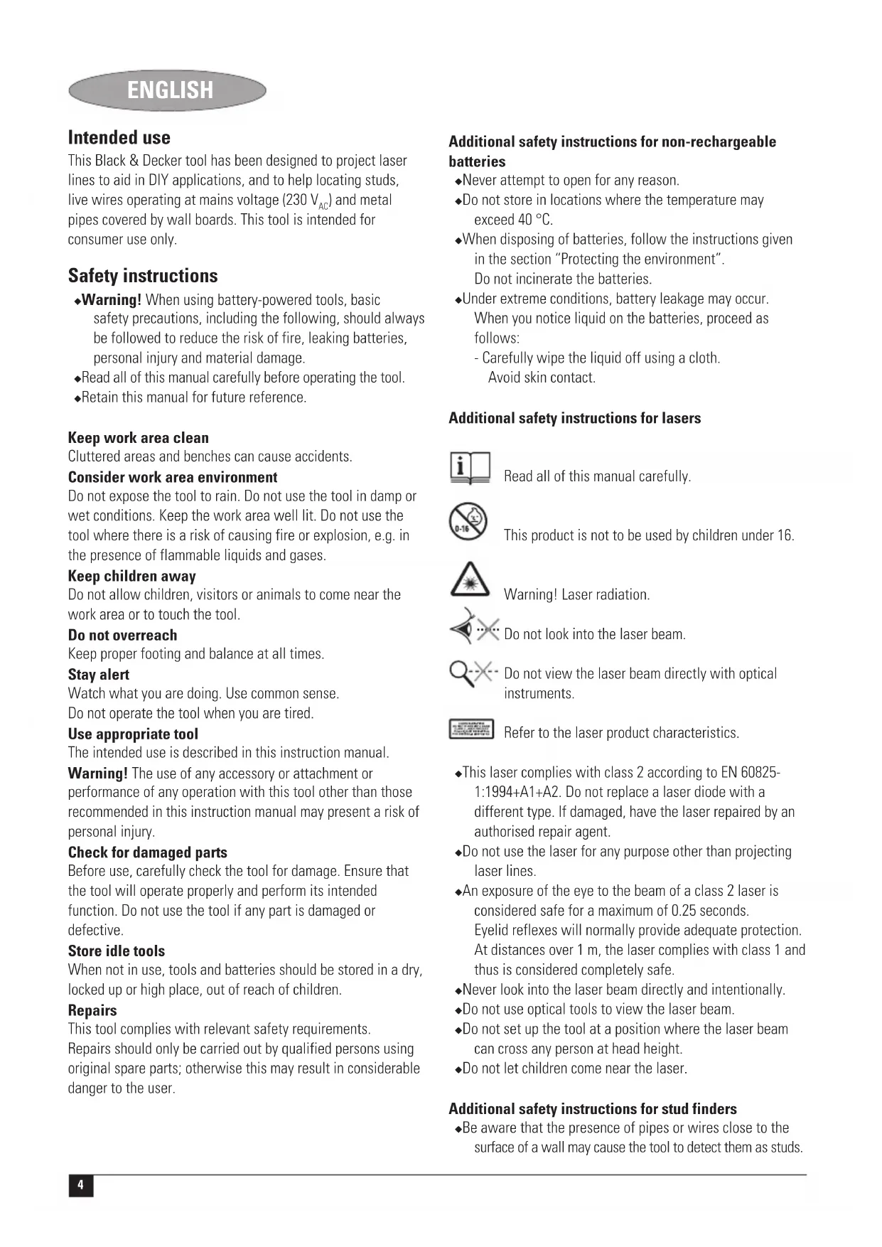
This Black & Decker tool has been designed to project laser lines to aid in DIY applications, and to help locating studs, live wires operating at mains voltage (230V_AC) and metal pipes covered by wall boards. This tool is intended for consumer use only.
Safety instructions
Warning! When using battery-powered tools, basic safety precautions, including the following, should always be followed to reduce the risk of fire, leaking batteries, personal injury and material damage.
Read all of this manual carefully before operating the tool.
Retain this manual for future reference.
Keep work area clean
Cluttered areas and benches can cause accidents.
Consider work area environment
Do not expose the tool to rain. Do not use the tool in damp or wet conditions. Keep the work area well lit. Do not use the tool where there is a risk of causing fire or explosion, e.g. in the presence of flammable liquids and gases.
Keep children away
Do not allow children, visitors or animals to come near the work area or to touch the tool.
Do not overreach
Keep proper footing and balance at all times.
Stay alert
Watch what you are doing. Use common sense.
Do not operate the tool when you are tired.
Use appropriate tool
The intended use is described in this instruction manual.
Warning! The use of any accessory or attachment or performance of any operation with this tool other than those recommended in this instruction manual may present a risk of personal injury.
Check for damaged parts
Before use, carefully check the tool for damage. Ensure that the tool will operate properly and perform its intended function. Do not use the tool if any part is damaged or defective.
Store idle tools
When not in use, tools and batteries should be stored in a dry, locked up or high place, out of reach of children.
Repairs
This tool complies with relevant safety requirements.
Repairs should only be carried out by qualified persons using original spare parts; otherwise this may result in considerable danger to the user.
Additional safety instructions for non-rechargeable batteries
Never attempt to open for any reason.
Do not store in locations where the temperature may exceed 40^
- When disposing of batteries, follow the instructions given in the section "Protecting the environment". Do not incinerate the batteries.
Under extreme conditions, battery leakage may occur. When you notice liquid on the batteries, proceed as follows:
- Carefully wipe the liquid off using a cloth.
Avoid skin contact.
Additional safety instructions for lasers

Read all of this manual carefully.

This product is not to be used by children under 16.

Warning! Laser radiation.

Do not look into the laser beam.

Do not view the laser beam directly with optical instruments.

Refer to the laser product characteristics.
This laser complies with class 2 according to EN 60825-1:1994+A1+A2. Do not replace a laser diode with a different type. If damaged, have the laser repaired by an authorised repair agent.
Do not use the laser for any purpose other than projecting laser lines.
An exposure of the eye to the beam of a class 2 laser is considered safe for a maximum of 0.25 seconds. Eyelid reflexes will normally provide adequate protection. At distances over 1m the laser complies with class 1 and thus is considered completely safe.
Never look into the laser beam directly and intentionally.
Do not use optical tools to view the laser beam.
Do not set up the tool at a position where the laser beam can cross any person at head height.
Do not let children come near the laser.
Additional safety instructions for stud finders
Be aware that the presence of pipes or wires close to the surface of a wall may cause the tool to detect them as studs.
Additional safety instructions for pipe and wire detectors
Do not use the tool to detect AC voltage in uninsulated, exposed or free wires.
Do not use the tool as a substitute for a voltmeter.
Be aware that the tool may not always properly detect all pipes and wires. The following conditions can cause inaccurate results:
Low battery
- Thick walls with thin pipes or wires
- Very thick walls
- Very deep wires or pipes
Walls covered with metal
- Very humid conditions
- Shielded cables
Before use, always test the tool by detecting a known pipe or wire.
If in doubt contact a qualified contractor.
Warning! This tool will not detect wires in circuits isolated from the mains supply, cables operating at direct current (DC) or wires used for telecommunication or computer systems. Hidden wires (e.g. wall lights) may not be detected when switches are in the off position.
Warning! This tool will not detect pipes of any other material than metal.
Features
- On/off switch (laser)
- On/off switch (stud/metal finder)
- Mode selector key
- LCD screen
- LED indicator (wire detector)
- Wall mount holder
- Laser apertures
Fig. A
- Wallpin
- Keyhole wall mount
Assembly
Fitting the battery (fig. B)
Remove the battery cover (10) from the tool.
Insert the batteries into the tool in the orientation as shown.
Refit the cover and let it click into place.
Wall mounting (fig. A & C)
The tool can be mounted to walls using one of the wall mounts (8 or 9).
Wall pin
If the tool is mounted to drywall or other soft materials, the wall pin (8) must be used. The position of the laser line will line up with the mounting location of the pin.
Remove the protective cap (11) from the pin (12) and store it on the insert as shown (fig. C).
Hold the wall pin at the required height in front of a suitable location and press the pin straight into the wall.
Install the tool by hanging the holder (6) on the wall mount.
Warning! The pin of the insert is sharp and should be handled with care. Replace the protective cap immediately after removing the insert from the wall.
Keyhole wall mount
For surfaces other than drywall, the keyhole wall mount (9) can be used with a screw in a predrilled hole. The position of the laser line will line up with the mounting location of the screw.
Hang the wall mount on a screw mounted at the required height on a suitable location.
Install the tool by hanging the holder (6) on the wall mount.
Use
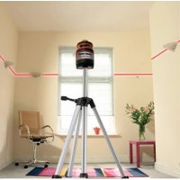
Using the laser level function (fig. D & E)
Hang the tool on the wall using the appropriate wall mount.
Push the on/off switch (1) up to switch the tool on.
The auto levelling indicator (13) will light up and swing while the tool is calibrating.
Note: the laser lines will only be level if the tool is kept within 5^ from vertical.
Push the on/off switch (1) down to switch the tool off.
Selecting the operating mode (fig. D)
The operating mode is indicated on the display (4).
For the detection of studs, press the mode selector key (3) as necessary until the 'STUD' position (15) is selected.
For the detection of metal studs, pipes, etc., press the mode selector key (3) as necessary until the 'METAL' position (16) is selected.
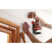
Using the stud finder function (fig. D & F)
You can use this function to find wooden and metal studs through drywall boards up to 19mm thick.
Set the required operating mode.
Place the tool flat against the wall as shown.
Keep the on/off switch (2) depressed
The scanner bars (17) will light up and the buzzer will sound once while the tool is calibrating. After calibration is completed (18):
Slowly slide the tool in a horizontal direction. Make sure not to tilt or lift the tool.
ENGLISH
When the first scanner bar (17) lights up, slow down and slide the tool further until the buzzer sounds and all scanner bars are on.
This position indicates the one edge of the stud.
Mark this position through the hole underneath the holder (6).
Move the unit further until the scanner bars are off.
While still keeping the on/off switch (2) depressed, move the tool in the opposite direction.
- When the first scanner bar (17) lights up, slow down and slide the tool further until the buzzer sounds and all scanner bars are on.
This position indicates the other edge of the stud.
Mark this position through the hole underneath the holder (6).
The centre of the stud is between the two marks.
Using the metal finder function (fig. D & F)
You can use this function to find metal pipes through drywall boards up to 25mm thick. You can also use this function to check whether a stud that has been detected in stud mode, is of metal.
- Set the required operating mode.
Place the tool flat against the wall as shown. - Keep the on/off switch (2) depressed.
The scanner bars (17) will light up and the buzzer will sound once while the tool is calibrating. After calibration is completed (18):
Move the tool slowly and smoothly across the surface. Make sure not to tilt or lift the tool.
- When the first scanner bar (17) lights up, slow down and slide the tool further until the buzzer sounds and all scanner bars are on.
This position indicates the location of a metal object.
After detecting the work area repeat the testing procedure to confirm the operation of the unit.
Using the wire detector function (fig. G)
You can use this function to find live wires through drywall boards up to 38mm thick. The function works continuously in all detector modes.
Warning! Test the unit on a known AC current before use.
Make sure the unit is away from the area being scanned and any other AC current source. Static charge may interfere detection on both sides of the wire, resulting in limited accuracy.
- Keep the on/off switch (2) depressed.
The red LED indicator (5) will light up and the buzzer will sound once while the tool is calibrating. After calibration is completed:
Move the tool slowly and smoothly across the surface, approaching from different directions.
Make sure not to tilt or lift the tool.
When an AC source is located, the red LED indicator (5) will blink.
After detecting the work area repeat the testing procedure to confirm the operation of the unit.
Hints for optimum use
Detecting studs
Check the area to be detected for regular spacing. Studs or joists are usually spaced 400 or 600~mm apart, and are 44 or 47mm in width. Any objects closer together or of a different width may not be a stud or joist.
Low battery indicator (fig. D)
The LCD screen will display a low battery symbol (19) when the battery is nearly empty.
Replace the battery on time.
Protecting the environment
Separate collection. This product must not be disposed of with normal household waste.
Should you find one day that your Black & Decker product needs replacement, or if it is of no further use to you, do not dispose of it with household waste. Make this product available for separate collection.

Separate collection of used products and packaging allows materials to be recycled and used again. Re-use of recycled materials helps prevent environmental pollution and reduces the demand for raw materials.
Local regulations may provide for separate collection of electrical products from the household, at municipal waste sites or by the retailer when you purchase a new product.
Black & Decker provides a facility for the collection and recycling of Black & Decker products once they have reached the end of their working life. To take advantage of this service please return your product to any authorised repair agent who will collect them on our behalf.
You can check the location of your nearest authorised repair agent by contacting your local Black & Decker office at the address indicated in this manual. Alternatively, a list of authorised Black & Decker repair agents and full details of our after-sales service and contacts are available on the Internet at: www.2helpU.com
Battery

At the end of their useful life, discard batteries with due care for our environment.
Remove the battery as described above.
- Place the battery in a suitable packaging to ensure that the terminals cannot be short-circuited.
- Take the battery to a local recycling station.
Technical data
BDL230S
Voltage V 9
Battery size 6LR61
Wave length nm 630-675
Laser class 2
Laser power mW < 2.2
Accuracy (at 3m mm +/− 3
Operating temperature ^ C0 - 40
Weight kg 0.45
EC declaration of conformity
BDL230S
Black & Decker declares that these products conform to:
89/336/EEC, EN 61010, EN 60825

Kevin Hewitt
Director of Consumer Engineering
Spennymoor, County Durham DL16 6JG
United Kingdom
1-2-2006
Guarantee
Black & Decker is confident of the quality of its products and offers an outstanding guarantee. This guarantee statement is in addition to and in no way prejudices your statutory rights. The guarantee is valid within the territories of the Member States of the European Union and the European Free Trade Area.
If a Black & Decker product becomes defective due to faulty materials, workmanship or lack of conformity, within 24 months from the date of purchase, Black & Decker guarantees to replace defective parts, repair products subjected to fair wear and tear or replace such products to ensure minimum inconvenience to the customer unless:
The product has been used for trade, professional or hire purposes;
The product has been subjected to misuse or neglect;
The product has sustained damage through foreign objects, substances or accidents;
Repairs have been attempted by persons other than authorised repair agents or Black & Decker service staff.
To claim on the guarantee, you will need to submit proof of purchase to the seller or an authorised repair agent. You can check the location of your nearest authorised repair agent by contacting your local Black & Decker office at the address indicated in this manual. Alternatively, a list of authorised Black & Decker repair agents and full details of our after-sales service and contacts are available on the Internet at:
www.2helpU.com
Please visit our website www.blackanddecker.co.uk to register your new Black & Decker product and to be kept up to date on new products and special offers. Further information on the Black & Decker brand and our range of products is available at www.blackanddecker.co.uk
DEUTSCH
Director of Consumer Engineering
Spennymoor, County Durham DL16 6JG
United Kingdom
1-2-2006
Garantine
Spennymoor, County Durham DL16 6JG
Royaume-Uni
1-2-2006
Garantie
Spennymoor, County Durham DL16 6JG, United Kingdom
1-2-2006
Garanzia
Director of Consumer Engineering Spennymoor, County Durham DL16 6JG, United Kingdom 1-2-2006
Garantie
Spennymoor, County Durham DL16 6JG
United Kingdom
1-2-2006
Garantía
Spennymoor, County Durham DL16 6JG
United Kingdom
1-2-2006
Garantia
Forvaras utom rackhall for barn
Director of Consumer Engineering
Spennymoor, County Durham DL16 6JG
United Kingdom
1-2-2006
Reservdar / reparationer
Director of Consumer Engineering Spennymoor, County Durham DL16 6JG, United Kingdom 1-2-2006
Director of Consumer Engineering
Spennymoor, County Durham DL16 6JG
United Kingdom
1-2-2006
Reservedele / reparationer
Varoitus! Lasersately.

Director of Consumer Engineering
Spennymoor, County Durham DL16 6JG
United Kingdom
1-2-2006
Mn xnpaonoiieTe to epyaIio otav iote koupaevoC.
XpnoHOnToieTe To oWTo EpyaEio
H evdeiyevn xnpoionoinan avapepetal oaeutc tic oonyie xpoewc.
Ppoox! Too n xpon eApntmuatwv n npoogkov o0o kal npaypaTOnoion epyaownou dEv ouviotwta otic odnyie autec eykuovi kivduvo tpauaiou.
EaeyxTe eav to epyaieio oac exi 6nae
Piv ano m xpon, eYeTe npoeekTka to epyaiaio yia tuxov Znuec. Beaowte 0ti to epyaiaio aeitoupyei kavovika kal Xpnoiotaitei Tai ia to okoia yia tov onio npoopiZetai. Mn xpanoiaite To epyaiaio av kaioio EApntma tou napouiae iAattwa.
duayetyaepyaleiaoaeaoaaeupeos
Otav xv npoioiouvtai, ta epyaia kai o i nataie nperti va anoekouvtai e npo xwpo, jaepia ano ta naia.
Emokuees
To epyaieio auto oumuoppwveiau ie TIC oxetikec npoutoeoeic aoepaiaac. O EIOKEuec 8a npetv a yivovta uvo ano EIOKEUevouc TeXVIKOUc kai e T xPon anokkoiotikayvnaowavntalakTKw,diapopeTtAunapxTe To evoxoepvo oobapou kivovouyia to xPonm.
Uunnpwpatikcs obnyies aoaaleia yia n enavaopoptoevc matarie
Spennymoor, County Durham DL16 6JG, United Kingdom
1-2-2006
Eyyunon
H Black & Decker éival αiyoupn γia tv nioTnta twv npoiovtw mcai napexei onmuavtkéyyunon. H napouca ypantnéyyunon anoteAe i npoogeto dikaiwmaac kai dey zniwve ta ouvtayatika oac dikaiwma. H eyyunon ioxuei evtoc mcs enkpataig Twv Kpatw Meawm Eupwnaikns Evomega cai ts Eupwnaikns Zwnc Eaeuepow Suvaalayov.
επeipintwn nou kanoio npoiov mC Black & Decker npouiaoei baaBn eaiTiac eataikwv uikwv, noiotntac epyaiaac n eaauicns ouawviae tnc npodiaypae c vtoc 24 nuwv ano tv nuepounvia ayopac, n Black & Decker eyyuatai tv avtikataotaon twv eaattwaatikov tmuatowv, tv eniokueun npoiovtwv nou exouv unooTei eloyn othopa loywxphoc n tv avtikataotaon twv npoiovtwv npokeivou va eaoaiaei tv elaxiotn evoxnon otous nealates mC, ektos av:
To npoiov exi xpnooionei o epyaiako, enayveaatiko nepiBaAiov n av exi evokiaot
Exiyiveeepaaleynxpontounpoiovtocnavexetaapaeanthei
To npoiov exi unootei ano aaaaavtikeeva, ano ouie n loyaw atuxmuatos
Exi yivei npooiaeia eiokeunc ano un Eouoiodotneva Kevtpa eniokeuw n ao npoownk o nou dev avnke I TO npooikoc Black & Decker
Ia va Ixuoei n Eyyunon, npenla v unobalaet e anodEeyn ayopac stov nolntn to Eouoiobotnevo kevtpo EIOKEUw. Evnpwoite yia to nnoieotepo Kevtpo EIOKEUw Tn pioxnc oac, EIKoivwovtae u ta ypaeia tC Black & Decker ot thieuvon nou avypapetai oTo Exyepidio. Eionc, ia va nnpoopnptheta iya ta Eouoiobotneva kevtpa EIOKEUw TnC Black & Decker, tic AEToupeiec kai touc apoibiouc twv unpeowv nou napexovtai mTa nV nWanon, npopeite va avatpeTe OTO AiaiktuO tn DUEbuvon:
www.2helpU.com
Papakaouue va eiokeptte TnV tooiaa ma
www.blackanddecker.com yia va kataxwpnoeTo voe oac
npoiov Black & Decker ka yia va evnepwveote yia ta vea
npoiovta ka tic bokc npooopoc. Iepioootepc
nnpopopie c oxetka m npapka Black & Decker ka m oipa
npoiovtwu aeg a Bpeite ot n ducuvon
www.blackanddecker.com
| Australia Black & Decker (Australia) Pty. Ltd. Tel. 03-8720 510020 Fletcher Road, Mooroolbark, Victoria, 3138 Fax 03-9727 5940 | |
| België/Belgique Black & Decker (Belgium) N.V. Tel. 015 - 47 92 11Campus Noord, Schaliënhoevedreef 20E Fax 015 - 47 92 102800 Mechelen | |
| Danmark Black & Decker Tel. 70 20 15 15Sluseholmen 2-4, 2450 København SV Fax 36 94 49 01Internet: www.blackanddecker.dk | |
| Deutschland Black & Decker GmbH Tel. 06126/21 - 0Black & Decker Str. 40, D - 65510 Idstein Fax 06126/21 29 80 | |
| Ελλάδα Black & Decker (Ελλάς) A.E. Στράβωνος 7 & Αεωφ. Bουλιαγμένης 159 Φαξ 210 8983285166 74 Γλυράδα - Αθήναwww.blackanddecker.gr | |
| Espana | Black & Decker Ibérica, S.C.A. |
| Parque de Negocios "Mas Blau" | |
| Edificio Muntadas, c/Bergadá, 1, Of. A608820 El Prat de Llobregat (Barcelona) | |
| France | Black & Decker (France) S.A.S.B.P. 21, 69571 Dardilly Cedex |
| Helvetia | ROFO AGGewerbezone Seeblick3213 Kleinbosingen |
| Italia | Black & Decker Italia SpAViale Elvezia 220052 Monza (MI) |
| Nederland | Black & Decker BeneluxJoulehof 12, 4622 RG Bergen op Zoom |
| New Zealand | Black & Decker Tel. 09 579 760081 Hugo Johnston DrivePenrose, Auckland, New Zealand |
| Norge | Black & Decker (Norge) A/SPostboks 4814, Nydalen, 0422 OsloInternet: www.blackanddecker.no |
| Österreich | Black & Decker Vertriebsges.m.b.HErlaerstraße 165, 1231 Wien |
| Portugal | Black & Decker Tel. 214667500Rua Egas Moniz 173S. João do Estoril2766-651 Estoril |
| Suomi | Black & Decker OyKeilasatama 3, 02150 Espoo |
| Black & Decker Oy,Kägelhamnen 3, 02150 Esbo | |
| Sverige | Black & Decker ABFabriksg. 7, 412 50 Göteborg |
| Türkiye | İntratek Mühendislik ve Düsseldorf Tic. A.§Atatürk Mah. Girne Cad. No. 4534750 Küçukbkakköy Kadiköy Istanbul |
| United Kingdom | Black & Decker Tel. 01753 511234210 Bath RoadSlough, Berkshire SL1 3YD |
| Middle East & Africa | Black & Decker (Overseas) A.G.PB 5420, Dubai, United Arab Emirates Fax +971 4 2826466 |
Dealer address Date of purchase
Händleradresse Kaufdatum